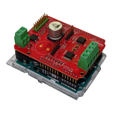
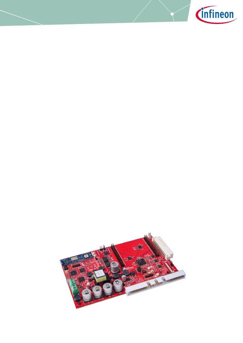
Demoboard BTS3011TE
User Manual
About this document
Scope and purpose
This document describes how to use the Demoboard BTS3011TE
Intended audience
Engineers, hobbyists and students who want to switch 12V loads in their Arduino UNO projects or evaluate the
performances of the BTS3011TE with usual lab equipements (waveform generator, power supply, etc…)
Table of contents
About this document....................................................................................................................... 1
Table of contents............................................................................................................................ 1
1Getting Started ...................................................................................................................... 3
1.1 BTS3011TE Shield Overview ...................................................................................................................3
1.3 Key Features ............................................................................................................................................4
1.4 Demoboard Package Contents...............................................................................................................4
1.5 Typical Connection .................................................................................................................................4
1.5.1 With Arduino UNO Shield...................................................................................................................4
1.5.2 Without Arduino UNO ........................................................................................................................4
2Demoboard Configuration....................................................................................................... 5
2.1 STATUS Pin Connection..........................................................................................................................5
2.1.1 Overcurrent limitation / Short circuit behavior ................................................................................6
2.1.3 Behavior with overload current below current limitation trigger level...........................................7
3Software Utilisation ............................................................................................................... 8
3.1 Installation...............................................................................................................................................8
3.2 Features...................................................................................................................................................8
3.2.1 Overview Panel...................................................................................................................................8
3.2.2 Control Panel......................................................................................................................................9
3.2.4 Alternative Command Panel............................................................................................................10
4Board Connector Description..................................................................................................11
4.1 Power Connector...................................................................................................................................11
4.2 Arduino/XMC1100 Connectors..............................................................................................................11
4.2.1 Connector SV1..................................................................................................................................11
4.2.2 Connector SV2..................................................................................................................................12
4.2.3 Connector SV3..................................................................................................................................12
4.2.4 Connector SV4..................................................................................................................................12
4.4 Push Buttons and Jumper ....................................................................................................................13
4.4.1 Push Button SW1 / SW2....................................................................................................................13
4.4.2 Jumper JP8 ......................................................................................................................................13
4.5 Test Points.............................................................................................................................................13
5Schematic ............................................................................................................................14


