2
4. Using the Boat
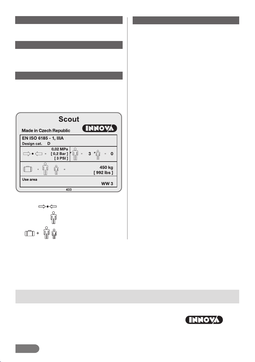
The Scout is a three-seat infl atable canoe with a self-draining
bottom.
Whenever the canoe is used on waterways, Waterway Traffi c
Rules should be observed. Operation of the Baraka infl atable
canoe does not require any licence provided the people who
operate the canoe know the techniques of small boat operation
within the scope necessary for its operation, as well as the valid
navigation rules of the particular country.
The design of the canoe enables it to be used it on wild waters
up to Diffi culty Grade WW 3, for water-based tourism activi-
ties on calm rivers and lakes, and expeditions requiring lots of
baggage. The canoe’s advantages are good stability, manoeu-
vrability, space-saving design, easy transport and long lifetime.
The canoe is propelled by 2 paddlers sitting on the seats. The
seats are adjustable in the longitudinal direction according to
the paddlers’ needs and the distribution of baggage in the ca-
noe. All people in the boat must wear fl otation life-jackets. Use
canoe paddles.
When using the canoe on wild water, the paddlers kneel, sup-
ported by the seats; their thighs are fi xed by thigh-straps laced
through the fi xtures on the bottom at the appropriate distance
from the seat. The fi xing straps are equipped with a safety clip
that enables safe abandonment of an overturned canoe.
The drainage sleeve (18) in the rear part of the bottom secures
water drainage upon canoe fl ooding in rapids. Roll the drainage
sleeve into the boat during boating.
ATTENTION
The maximum operational pressure in air chambers is
0.02 MPa. If the ambient temperature increases (e.g.
owing to sunlight), the pressure in the air chambers of the
canoe can rise rapidly. We recommend releasing some air
from all air chambers of the canoe after pulling it out of
the water. This will prevent possible destruction of the air
chambers. However, do not forget to continuously check
air pressure in the chambers afterwards, too.
ATTENTION
When using the boat, always seal the valves with their
valve caps. This will keep dirt out of the valves. Dirt can-
cause leaky valve seals.
3. Inflation Instructions
Lay out the canoe. Attach the seats and fi xation straps using
screws and plastic nuts – see Details A and B. Alternatively,
the seats can be laced by means of ropes (24) – see Detail F.
Infl ate the air chambers in the following order: sidewall cylin-
ders (1) and the bottom (2).
A foot pump or piston pump with a valve adapter is the best
way of infl ating the craft (the valve adapter is included in the
gluing set) – see Picture 3b. Prior to infl ating the canoe, check
the valves. Set the valves to the closed position. For how to
use the valves – see Picture 3.
Infl ate the air chambers to the required operational pressure.
Use a pressure gauge with a corresponding adaptor (optio-
nal equipment) for measuring the correct operating pressure
– see Picture 3a. The spanner for assembling the valves is an
optional accessory – see Picture 3c.
2. Technical Description
Standard version – see Picture 1
The Scout infl atable canoe consists of three main air chamb-
ers. Two infl atable fl at sidewall cylinders (1) and an infl atable
V-profi le bottom (2). The main air chambers are equipped with
valves (3) for infl ating and defl ating the canoe, regulating pre-
ssure in the chambers by releasing the valves and measuring
the pressure in the chambers. The bottom of the canoe is also
equipped with a safety relief valve (4). The canoe also con-
tains three seats (5). The front and rear seats are equipped
with fastening straps (6) for use on wild water; the central seat
has no straps. The seats and fastening straps are attached
to fi xtures (9) inside the canoe by means of screws (7) and
plastic nuts (8) – see Details A and B. The fastening strap
consists of the actual strap (6) and a plastic buckle (10) and
passes through the bottom fi xture (11). T-shaped aluminium
bracings – T-BONES (12) are located below each seat.
Safety ropes (13) with tubular handles (14) for carrying the
canoe are located on the bow and stern. Flexible loops with
plastic balls (15) are designed for attaching a coiled ancho-
ring rope (16) – see Detail C. Belt fi xtures (17) are designed
for fastening baggage. The rear part of the bottom contains
a drain sleeve (18). The sleeve can be closed by rolling it up
and fastening with a buckle.
The canoe is supplied in a carrying bag. The accessory kit
also includes a foam sponge in a mesh bag, 2 fl exible loops
with balls (19) to attach the pump – see Detail D, a gluing
set containing adhesive, patches, sandpaper, a valve adapter,
a spare screw and plastic nut for attaching the seat, a spare
screw for the T-BONES, and repair instructions.
The T-BONES System – See Detail A
The T-BONES system enables variable adjustments of the ri-
gidity, profi le and stability of the canoe to suit the user and the
conditions. The canoe can be used without the T-BONES bra-
cings. The seats (5) in this version are attached to the bottom
part of straps (9) in order to achieve maximum stability; this
version is designed to be used by beginners on still and calm
waters up to Diffi culty Grade WW1.
T-BONES – assembly in the top part – the seats (5) are atta-
ched to the top of the straps (9). The canoe’s profi le remains
straight; the primary stability lets you paddle with confi dence.
This version of canoe is designed to be used by intermediate
users on waters up to Diffi culty Grade WW3.
T-BONES – assembly in the bottom part – the seats (5) are
attached to the bottom of the straps (9). This layout keeps the
canoe as rigid as possible and ensures the largest keel bend.
The sidewall cylinders in the central section are bent upwards.
This version is designed for skilled canoeists due to its low
primary stability. However, it off ers maximum performance and
speed on the water.
T-BONES assembly instructions – See Picture 2
2a) Make sure that you have the following parts available: seat
(5), T-Bones bracing (12), 4 M6x35 screws (7), 4 M6 plastic
nuts (8), 1 M8x25 screw (20) and a 5mm hexagonal spanner
(21), 1 pc of stainless steal pad (25).
2b), 2c), 2d) Insert the T-Bones bracing into the holes on stra-
ps (9).
2e) Erect the T-Bones perpendicularly to the seat and align the
hole in the seat (22) with the T-Bones hole (23). Put a stainless
steel pad (25) on the hole in the seat and T-Bones and fi x using
the screw (20) and fasten it with the hexagonal spanner (21).