Inspur NF5488A5 User manual

Inspur Server User Manual
NF5488A5

© Copyright Inspur 2020. All rights reserved.
No part of this document may be reproduced or transmitted in any form or by any means
without prior written consent of Inspur.
The information in this manual is subject to change without notice.
Inspur is the registered trademark of Inspur. All the other trademarks or registered
trademarks mentioned in this manual are the property of their respective holders.
Edition: 1.3
June,2021
Edition statement: Product Specifications updated.

Abstract
This manual contains technical informaon such as specicaons, hardware operaons,
soware conguraon, fault diagnosis, etc., which is relevant to the maintenance and
operaon of this server.
It is recommended that server installation, configuration and maintenance is performed by
experienced technicians only.
Target Audience
This manual is intended for:
●Technical support engineers
●Product maintenance engineers
●Technicians
Warnings
This manual introduces the NF5488A5 server’s technical features, system installation and setup,
which will help the user to understand how best to utilize the server and all its functions.
1.For your safety, please do not disassemble the server’s components arbitrarily. Please do
not extend configuration or connect other peripheral devices arbitrarily. If needed, please
contact Inspur for our support and guidance.
2.Before disassembling the server’s components, please be sure to disconnect all the power
cords connected to the server.
3.BIOS and BMC setup is a significant factor in correctly configuring your server. If there are
no special requirements, it is suggested to use the Default Values and not alter the parameter
settings arbitrarily. After the first login, please change the BMC user password in time.
4.Please install the product-compatible operating system and use the driver provided by
Inspur. If you use an incompatible operating system or non-Inspur driver, it may cause
compatibility issues and affect the normal use of the product, Inspur will not assume any
responsibility or liability.
Inspur is not responsible for any damages, including loss of profits, loss of information,
interruption of business, personal injury, and/or any damage or consequential damage
without limitation, incurred before, during, or after the use of our products.

Contents
1 Safety Instructions......................................................................................................................... 1
2 Product Specifications .................................................................................................................. 11
2.1 Overview .................................................................................................................................... 11
2.2 Features and Specifications........................................................................................................ 12
3 Component Identification ............................................................................................................. 14
3.1 Front Panel Components............................................................................................................ 14
3.2 Front Control Panel Buttons and LEDs........................................................................................ 14
3.3 Drive Tray LEDs ........................................................................................................................... 15
3.4 Rear Panel Components ............................................................................................................. 15
3.5 Motherboard Components......................................................................................................... 16
4 Operations..................................................................................................................................... 18
4.1 Power up the Server................................................................................................................... 18
4.2 Power down the Server.............................................................................................................. 18
4.3 Extend the Server from the Rack................................................................................................ 18
4.4 Remove the Access Panel........................................................................................................... 19
4.5 Install the Access Panel .............................................................................................................. 20
4.6 Install the Server......................................................................................................................... 20
4.7 Remove the GPU BOX................................................................................................................. 20
4.8 Remove the IO BOX .................................................................................................................... 21
5 Setup ............................................................................................................................................. 22
5.1 Optimum Environment............................................................................................................... 22
5.2 Rack Warnings ............................................................................................................................ 24
5.3 Identifying the Contents of the Server Shipping Carton.............................................................25
5.4 Installing Hardware Options ....................................................................................................... 25
5.5 Installing the Server into the Rack.............................................................................................. 25
5.6 Installing the Operating System.................................................................................................. 26
6 Hardware Options Installation....................................................................................................... 27
6.1 Overview .................................................................................................................................... 27
6.2 Processor Option........................................................................................................................ 27
6.3 Memory Option.......................................................................................................................... 32

6.4 Hard Drive Option....................................................................................................................... 34
6.5 Power Supply Option.................................................................................................................. 35
6.6 Air Baffle Option......................................................................................................................... 35
7 Cabling........................................................................................................................................... 37
8 Common Faults and Troubleshooting............................................................................................ 34
8.1 Hardware Problems.................................................................................................................... 34
8.2 Software Problems ..................................................................................................................... 37
9 Battery Replacement..................................................................................................................... 39
10 Regulatory Compliance Notices................................................................................................... 40
10.1 Regulatory Compliance Identification Numbers....................................................................... 40
10.2 Federal Communications Commission Notice.......................................................................... 40
10.3 European Union Regulatory Notice.......................................................................................... 41
10.4 Disposal of Waste Equipment by Users in the European Union............................................... 41
10.5 Korean Notice........................................................................................................................... 42
10.6 Chinese Notice.......................................................................................................................... 42
10.7 Battery Replacement Notice .................................................................................................... 42
11 Electrostatic Discharge ................................................................................................................ 44
11.1 Preventing Electrostatic Discharge........................................................................................... 44
11.2 Grounding Methods to Prevent Electrostatic Discharge ..........................................................44
12 Warranty...................................................................................................................................... 45
12.1 Introduction.............................................................................................................................. 45
12.2 Warranty Service ...................................................................................................................... 45
12.3 Warranty Exclusions ................................................................................................................. 46

1
Safety Instructions
1. Safety Instructions
WARNING: Please be advised to follow the instructions below for safety. Failure to do so
could result in potential dangers that may cause property loss, personal injury or death.
1. The power supplies in the system may produce high voltages and energy hazards that
may cause personal injury. For your safety, please do not attempt to remove the cover
of the system to remove or replace any component without assistance provided by
Inspur. Only service technicians trained by Inspur are authorized to remove the cover of
the host, and to remove and replace internal components.
2. Please connect the equipment to the appropriate power supply. Use only power
supplies with the correct voltage and electrical specifications according to the label. To
protect your equipment from damages caused by a momentary spike or plunge of the
voltage, please use relevant voltage stabilizing equipment, or uninterruptible power
supplies.
3. If you must use an extension cable, please use a three-core cable with properly
grounded plugs. Observe extension cable ratings. Ensure that the total rating of all
equipment plugged into the extension cable does not exceed 80 percent of the ratings
limit for the extension cable.
4. Please be sure to use the power supply components that come with the server, such as
power cable, power socket (if provided with the server) etc. For your safety, please do
not replace power cables or plugs randomly.
5. To prevent electric shock dangers caused by leakage in the system, please make sure
that the power cables of the system and peripheral equipment are correctly connected
to the earthed/grounded power socket. Please connect the three-core power cable
plug to the three-core AC power socket that is well earthed and easy to access. Be sure
to use earthing /grounding pin of power cables and do not use the patch plug or the
earthing/grounding pin unplugged with cables. In the case that the earthing/grounding
conductors are not installed and it is uncertain whether there are appropriate earthing/
grounding protections, please do not use or attempt to operate the equipment. Contact
and consult an electrician.
6. Please do not push any objects into the openings of the system. Doing so may cause

2
fire or electric shock.
7. Please place the system far away from the cooling plate and heat sources, and be sure
not to block the air vents.
8. Please be sure not to scatter food or liquid in the system or on other components, and
do not use the product in humid or dusty environments.
9. Using an incompatible battery may cause explosion. When battery replacement is
required, please consult the manufacturer first, and choose batteries of the same or
equivalent type. Do not disassemble, crush, puncture the batteries or make the external
connection point short circuit, and do not expose them in the environment over 60°C.
Never throw batteries into fire or water. Please do not attempt to open or repair the
batteries. Dispose of used batteries according to instructions. For battery recycling,
please contact the local waste recycling center.
10. Before installing equipment into the rack, please install all front and side stabilizers on
the independent rack first. Please install the front stabilizers first, if connecting with
other racks. Please install stabilizers before installing equipment into the rack. Failure to
install the corresponding stabilizers before installing equipment into the rack may cause
the cabinet to tip over, possibly resulting in severe injury. After installing the equipment
and other components into the rack, only one component can be pulled out from the
rack through its sliding part at one time. Pulling out several components at the same
time may cause the rack to turn over, resulting in serious personal injury.
11. A minimum of two people are required to safely move a rack. The racks are extremely
awkward and heavy, moving them without adequate, trained personnel could result in
severe injury or death.
12. It is prohibited to directly short-circuit the copper busbar. Please do not touch the
copper busbar when the rack is powered on.
13. This is Class A product, and may cause radio interference. In such case, users may need
to take necessary measures to mitigate the interference.
14. The equipment is intended for installation in a Restricted Access Location.
Note: The following considerations may help avoid the occurrence of problems that
could damage the components or cause data loss, etc.
1. In the event of the following, please unplug the power cable plug from the power

3
Safety Instructions
socket and contact Inspur’s customer service department:
1) The power cables, extension cables or power plugs are damaged.
2) The products get wet.
3) The products have fallen or have been damaged.
4) Other objects have fallen into the products.
5) The products do not or are unable to function normally even when attempting to
operate according to the instructions.
2. If the system becomes wet or damp, please follow these steps:
1) Power off the equipment, disconnect them with the power socket, wait for 10 to
20 seconds, and then open the host cover.
2) Move the equipment to a well-ventilated place to dry the system at least for 24
hours and make sure that the system is fully dried.
3) Close the host cover, reconnect the system to the power socket, and then power
on.
4) In case of operation failure or other abnormal situations, please contact Inspur and
get technical support.
3. Pay attention to the position of system cables and power cables-avoid placing wires in
high foot traffic locations. Please do not place objects on the cables.
4. Before removing the host cover, and/or touching the internal components, please
allow for the equipment to cool first. To avoid damaging the motherboard, please
power off the system and wait for five seconds, and then remove the components from
the motherboard and/or disconnect the peripheral device from the system. Please
remember that only service technicians trained by Inspur are authorized to remove the
cover of the host, and to remove and replace internal components.
5. If there is modem, telecom or LAN options installed in the equipment, please pay
attention to the followings:
1) In the case of thunder and lightning, please do not connect or use the modem.
2) Never connect or use the modem in a damp environment.
3) Never insert the modem or telephone cables into the socket of network interface
controller (NIC).
4) Before unpacking the product package, installing internal components, touching
uninsulated cables or jacks of the modem, please disconnect the modem cables.
6. In order to prevent electrostatic discharge from damaging the electronic

4
components in the equipment, please pay attention to the followings:
1) Please remove any static electricity on your body before dismounting or touching
any electronic component in the equipment, to prevent the static electricity from
conducting itself to the sensitive components. You may remove the static electricity
on the body by touching the metal earthing objects (such as the unpainted metal
surface on the rack).
2) Please do not take electrostatic sensitive components that are not ready to be
installed for application out of the antistatic package materials.
3) While working, please touch the earthing conductor or the unpainted metal
surface on the cabinet regularly to remove any static electricity from the body that
may damage the internal components.
7. Upon receiving the proper authorization from Inspur and dismounting the internal
components, please pay attention to the followings:
1) Switch the system power supply off and disconnect the cables, including all
connections of the system. When disconnecting the cables, please hold the
connector of the cables and slowly pull the plugs out. Never pull on the cables.
2) The products need to completely cool down before dismounting the host cover or
touching the internal components.
3) Before disassembling, assembling or touching any electronic components in the
equipment, you should first remove static electricity on your body by touching a
grounded metal object.
4) During the dismounting process, avoid making large movement ranges to prevent
damage to the components or scratching arms.
5) Handle components and plug-in cards with care. Please do not touch the
components or connection points on the plug-in cards. When handling the plug-in
cards or components, firmly grab the edges of the plug-in cards and components,
and/or their metal fixed supports.
8. During the process of rack installation and application, please pay attention to the
followings:
1) After the rack installation is finished, please ensure that the stabilizers have been
fixed to the rack and supported to ground, and the weight of the rack is firm on
ground.
2) Always load from the bottom up, and load the heaviest items first.

5
Safety Instructions
3) When pulling out the components from the rack, apply slight force to keep the rack
balanced.
4) When pressing down the release latch and the rail of components is sliding, please
be careful; as the sliding may hurt your fingers.
5) Do not overload the AC power supply branch circuits in the rack. The total load of
the rack should not exceed 80% of the ratings of the branch circuits.
6) Ensure that components in the rack have good ventilation conditions.
7) When repairing components in the rack, never step on any other components.
9. After receiving the server, please refer to the label on the top cover to remove the
screws on both sides of the chassis and then install it on the rack, to avoid damage to
the handles when you open the GPU BOX later without removing the screws.

6
2 Product Specifications
2.1 Overview
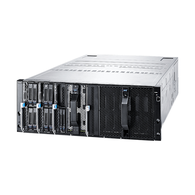
Inspur AI server NF5488A5 has high scalability, high performance, high energy efficiency,
flexible deployment and other features. Its AI computing performance can reach 2
petaflops, suitable for image & video, speech recognition, financial analysis, intelligent
customer service and other AI application scenarios. With the massive growth of data and
the rapid iteration of models, AI research institutes and commercial companies urgently
need to improve AI computing power to shorten the model training and development cycle.
At the same time, they hope to deploy AI infrastructure more quickly and economically, and
to realize the compatibility between the AI infrastructure and the legacy IT infrastructure
to save data center space and reduce costs. NF5488A5 uses the most advanced NVIDIA
NVSwitch interconnect architecture in the industry,and can be equipped with eight NVIDIA
SXM4 A100 Tensor Core 40GB/80GB GPUs interconnected at high speed in 4U space.The
direct P2P data interaction between any two GPUs can achieve 2 petaflops of AI computing
performance. . NF5488A5 adopts the most advanced high-speed NVIDIA NVSwitch™, which
enables P2P connection between any two of the 8 NVIDIA SXM4 A100 Tensor Core 40/80 G
GPUs at a total bandwidth of up to 600 GB/s in a 4U space. With 2 AMD EPYC 7002/7003
series PCIe 4.0 CPUs, together with xGMI-2, this server provides top-level computing
performance. A 4U chassis and power supply redundancy design enable NF5488A5 to be
widely applied to data center environments, especially mounted to the cabinets with
limited power consumption. Besides, NF5488A5 adopts a more flexible cluster deployment
scheme for integration from hardware to applications. Moreover, the 54V_VR power supply
offers higher power efficiency. A combination of the layered and zoned cooling channels
and an intelligent PID control strategy ensures optimal cooling performance. With
NF5488A5, AI users can build AI infrastructures and development environments efficiently
with high computing performance and low deployment and operational costs.

7
Product Specications
2.2 Features and Specifications
Processor
Processor type 2 × AMD® EPYC® Rome/Milan Processors (up to 225 - 240 W TDP)
Memory
Memory type DDR4 RDIMM/LRDIMM 3200MHz
Memory slot quantity 32
Total memory capacity Up to 2TB
GPU
HGX2 baseboard Supports 8* NVIDIA® Ampere SXM4 A100 40GB/80GB GPU, up to 400W;
Supports NVSwitch fully-connected topology
I/O
USB 2* front USB3.0 port
Network port 2*10G optical port
VGA 1* front VGA port
Mgmt 1* front RJ45 IPMI port,and 1* rear RJ45 Switch BMC port
PCIe Supports 4* PCIe Gen4 x16 25W low-profile PCIe card
Display
Controller type Integrated in Aspeed 2500 chip, supporting up to 1900*1200 resolution
Drive
Drive type
Up to 4 hot-swap NVMe SSDs,
4 built-in enterprise-class M.2 SSDs,
4 SATA/SAS SSDs,
and 2 onboard SATA/PCIe bus M.2 SSDs .
Power

8
Specifications 4* 3000W 80Plus Platinum PSU, supporting 3+1 redundancy
Power input Please refer to the power input on the nameplate label of the host
Physical
External packing
dimensions 722mm (W) x 368 mm (H) x 1168mm (D)
Host machine dimensions 448mm (W) x 175.5mm (H) x 850mm (D)
Weight
Full configuration:
NW 62kg, GW 95kg (Gross weight including host + packing box + rails + accessory
box)
Environmental
Operating temperature 5℃ ~35℃
Storage & transportation
temperature -40℃~60℃
Operating humidity 20%~90% relative humidity
Storage & transportation
humidity 20%~93% (40℃) relative humidity

9
Component Identication
3 Component Identification
3.1 Front Panel Components
Item Descripon
1Power button & LED
2 UID button & LED
3 System reset button
4 System failure LED
5-12 HDD 0-7
13 USB3.0 port x2
14 BMC management port
15 Ethernet port x2
16 VGA port
17 BMC debug port
18 UID button & LED
19 GPU BOX
3.2 Front Control Panel Buttons and LEDs

10
Item Descripon Status & Interpretaon
1Power button and LED
Steady green in power-on status
Steady orange in standby status
Long press to force a system shutdown
2 UID LED and button Turn on/off UID, blue on
3 System reset button Short press to force a system reset
4 System status LED
O in normal status
Steady red in case of power failure
Flashing red in case of abnormal power status
3.3 Drive Tray LEDs
Item Descripon Status & Interpretaon
1Activity status LED teady green: Normal
Flashing green: Read and write activity
2 Fault alarm LED
Steady red: A failure occurs
Steady blue: Drive posioning
Steady pink: RAID Rebuilding
3.4 Rear Panel Components
Item Descripon
1PSU0
2PSU1
3 PSU2
4 PSU3
5 FAN 0-5
6I/O Box A
7 I/O Box B

11
Component Identication
3.5 Motherboard Components
Item Descripon
1DIMM slots (CPU1)
2 SASHD connector 1
3 SASHD connector 0
4 Slimline connector x11
5 CPU1
6Motherboard handle
7 TPM connector
8 CPU0
9DIMM slots (CPU0)
10 TF slot
11 Le-ear front panel connector
12 Slimline_PCIe_Raid
13 Raid card connector
14 HDD_BP signal connector 1
15 HDD_BP signal connector 0
16 BMC_TF slot

12
Item Descripon
17 BMC debug port
18 UID buon
19 BMC/USB3.0 port x2
20 10G Ethernet port x2
21 VGA port
22 Slimline_PCIe_MB1
23 M.2 Riser slot
24 Motherboard handle
25 HDD_BP signal connectors
26 P12V_INPUT connector
27 PWR_PDB0 connector
28 PWR_PDB1 connector

13
Operations
4 Operations
4.1 Power up the Server
Insert the power cord plug, then press the Power Button.
4.2 Power down the Server
WARNING: To reduce the risk of personal injury, electric shock, or damage to the equipment,
remove the power cord to remove power from the server. The front panel Power Button
does not completely shut off system power. Portions of the power supply and some internal
circuitry remain active until AC power is removed.
IMPORTANT: If installing a hot-plug device, it is not necessary to power down the server.
1. Back up the server data.
2. Shut down the operating system.
3. Disconnect the power cords.
The system is now without power.
4.3 Extend the Server from the Rack
1. Follow the installaon guide, and loosen the four capve screws within the ears on both
sides by using a screwdriver.
2. Pull out the server slowly out of the rack. Install the liing handles on both sides. Move
the server onto an anstac bench.
WARNING: To reduce the risk of personal injury or equipment damage, be sure that the rack
is adequately stabilized before extending a component from the rack. A single server weighs
above 60kg and should be lied by at least four people or by using auxiliary equipment.

14
4.4 Remove the Access Panel
WARNING: To reduce the risk of personal injury from hot surfaces, allow the drives and the
internal system components to cool before touching them.
CAUTION: For proper cooling, do not operate the server without the access panel, air baffle,
or fan installed. If the server supports hot-plug components, minimize the amount of time
the access panel is open.
To remove the component:
1. Power down the server if performing a non-hot-plug installation or maintenance procedure.
2. Extend the server from the rack.
3. Use the screwdriver to loosen the security screw on the hood latch.
4. Lift up on the hood latch handle, and then remove the access panel.

15
Operations
4.5 Install the Access Panel
1. Place the access panel on top of the server with the hood latch open. Allow the panel to
extend past the rear of the server.
2. Push down on the hood latch. The access panel slides to a closed position.
3. Use the screwdriver to tighten the security screw on the hood latch.
4.6 Install the Server
1. After the installation/maintenance steps are completed, follow the installation guide and
lift the server chassis onto the rails. Push it into the rack.
2. Use a screwdriver to fix the captive screws within the ears on both sides to secure the
chassis onto the rack.
WARNING: A single server weighs above 60kg and should be lifted by at least four people or
by using auxiliary equipment.
4.7 Remove the GPU BOX
1. Open the handles on both sides of the GPU BOX chassis, as shown by ① in the following figure.
Note: Before opening the handles, check whether the screws on both sides of the chassis
are removed, if not removed, please remove them first to avoid damage to the handles.
2. Pull the GPU BOX outward. When the buttons on both sides are exposed, press the two
buttons at the same time to pull the GPU BOX out of the chassis completely. The GPU BOX is
Table of contents
Other Inspur Server manuals

Inspur
Inspur Yingxin NP3020M2 User manual
Inspur
Inspur NF5288M5 User manual
Inspur
Inspur NF5280M5 User manual
Inspur
Inspur NF5486M5 User manual
Inspur
Inspur NF3120M5 User manual
Inspur
Inspur NF5180M5 User manual

Inspur
Inspur Yingxin User manual

Inspur
Inspur Yingxin User manual
Inspur
Inspur NF8380M5 User manual

Inspur
Inspur NF5280M5 Instruction Manual

Inspur
Inspur NF8480M5 Instruction Manual

Inspur
Inspur Yingxin User manual
Inspur
Inspur NF5266M6 User manual

Inspur
Inspur NF8480M5 User manual

Inspur
Inspur Yingxin User manual

Inspur
Inspur NF5270M3 User manual
Inspur
Inspur NF5266M6 User manual
Inspur
Inspur NX8840 User manual

Inspur
Inspur Yingxin NX 5440 User manual
Inspur
Inspur ON5263M5 User manual
