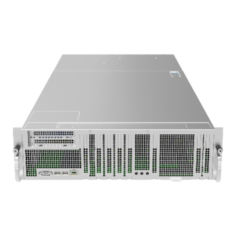
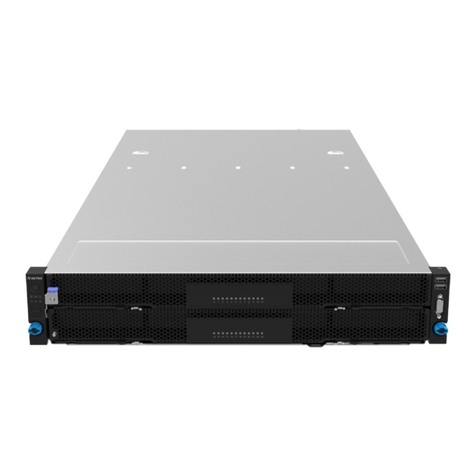
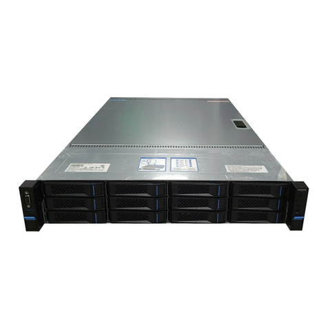
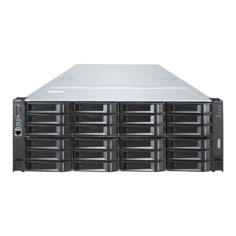
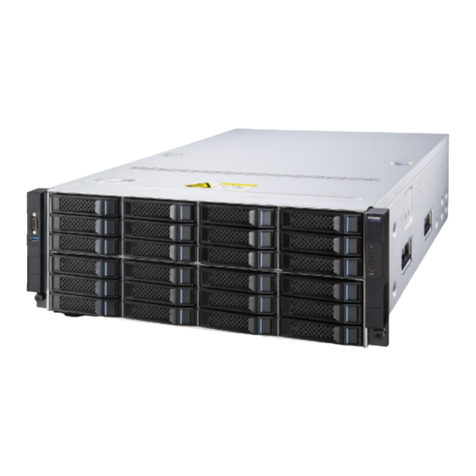
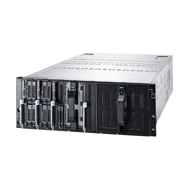
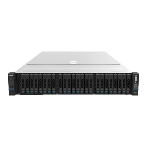
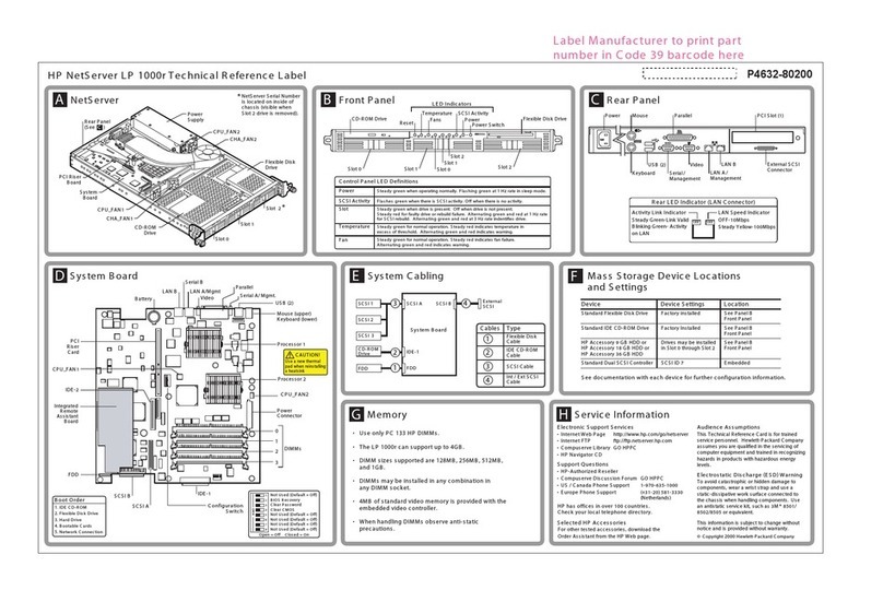
Inspur NF5266M6 User manual

Inspur Server NF5266M6
User Manual
Document Version: V1.1
Release Date: July 23, 2021

i
Copyright © 2021 Inspur Electronic Information Industry Co., Ltd. All rights reserved.
No part of this document may be reproduced or transmitted in any form or by any
means without prior written consent of Inspur.
Environmental Protection
Please dispose of product packaging by recycling at a local recycling center for a
greener planet.
Trademarks
Inspur and Inspur Logo are the registered trademarks of Inspur.
All the other trademarks or registered trademarks mentioned herein are the property of
their respective holders.
Security Statement
Inspur is intensely focused on server product safety and has placed a high priority on
this. For better understanding of our server products, carefully read through the
following security risk statements.
•When servers are to be repurposed or retired, it is recommended to restore their
firmware factory settings, delete information and clear logs from BIOS and BMC to
protect data privacy. Meanwhile, it is suggested to wipe the drive data thoroughly
and securely with third-party erasing tools.
•The products, services or features you purchased may obtain or use some personal
data (such as email address for alerts and IP address) during operation or fault
locating. There should be user privacy policies in place with adequate measures
implemented in accordance with the applicable laws to ensure that users' personal
data are fully protected.
•For server open source software statement, please contact Inspur Customer Service.
•Some interfaces and commands for production, assembly and return-to-depot, and
advanced commands for locating faults, if used improperly, may cause equipment
abnormality or business interruption. This is not described herein. Please contact
Inspur for such information.
•The external interfaces of Inspur servers do not use private protocols for
communication.
•Inspur has established emergency response procedures and action plans for
security vulnerabilities, so that product safety issues can be dealt with in a timely
manner. Please contact Inspur Customer Service for any safety problems found or

ii
necessary support on security vulnerabilities when using our products.
Inspur shall remain committed to safety of our products and solutions to achieve better
customer satisfaction.
Disclaimer
The purchased products, services and features shall be bound by the contract made
between Inspur and the customer. All or part of the products, services and features
described herein may not be within your purchase or usage scope. Unless otherwise
agreed in the contract, Inspur makes no express or implied statement or warranty on
the contents herein. Images provided herein are for reference only and may contain
information or features that do not apply to your purchased model. This manual is only
used as a guide. Inspur shall not be liable for any damage, including but not limited to
loss of profits, loss of information, interruption of business, personal injury, or any
consequential damage incurred before, during, or after the use of our products. Inspur
assumes you have sufficient knowledge of servers and are well trained in protecting
yourself from personal injury or product damages during operation and maintenance.
The information in this manual is subject to change without notice. Inspur shall not be
liable for technical or editorial errors or omissions contained in this manual.
Technical Support
Technical Service Hotline: 1-844-860-0011/1-760-769-1847
Address: No. 1036 Langchao Road, Jinan, PRC
Inspur Electronic Information Industry Co., Ltd.
Postal Code: 250101
Email: serversupport@inspur.com

iii
Foreword
Overview
This manual describes the server's specifications, features, hardware setup, warranty
information and troubleshooting, which will help users to understand how best to
utilize the server and all its functionalities.
Target Audience
This manual is intended for:
•Technical support engineers
•Product maintenance engineers
It is recommended that server installation, configuration, and maintenance is
performed by experienced technicians only.
Safety Precautions
•If your purchases do not include Inspur on-site installation service, make sure that
you inspect the shipping cartons before unpacking the equipment. If a shipping
carton appears severely damaged, water immersed, or the seal or
pressure-sensitive adhesive tape (PSA) is broken, report this based on your
purchase channel. If you purchased from a third-party supplier, contact your
supplier directly; if you purchased through Inspur direct sales stores, call Inspur
service hotline 1-844-860-0011/1-760-769-1847 for technical support.
•For your safety, please do not disassemble the server’s components, extend
configuration or connect other peripherals arbitrarily. You can contact Inspur for
our support and guidance.
•Before disassembling the server’s components, please be sure to disconnect all the
cables connected to the server.
•Please install the product-compatible operating system and use the driver that
comes with the server or provided by Inspur. You can go to our official site, on the
Top Navigator, click on Support > Product Support > Drivers, then find the correct
driver of your product based on the prompt. An incompatible operating system or a
non-Inspur driver may cause compatibility issues and affect the normal use of the
product. Inspur will not assume any responsibility or liability for this.
•BIOS and BMC setup is a significant factor in correctly configuring your server. If

iv
there are no special requirements, it is suggested to use the Default Values and not
alter the parameter settings arbitrarily. After the first login, please change the BMC
user password in time.
Symbol Conventions
The symbols that may be found in this document are defined as follows.
Symbol Description
A potential for serious injury, or even death if not properly
handled
A potential for minor or moderate injury if not properly handled
A potential loss of data or damage to equipment if not properly
handled
Operations or information that requires special attention to
ensure successful installation or configuration
Supplementary description of manual information
Revision History
Version Date Description of Changes
V1.0 2021/04/23 Initial release
V1.1 2021/07/23 Corrected some descriptions and improved the
figures

v
Table of Contents
1Safety Instructions......................................................................................1
1.1 Warnings.........................................................................................................1
1.2 Precautions .....................................................................................................2
2Product Specifications ................................................................................5
2.1 Introduction .................................................................................................... 5
2.1.1 24 × 3.5-inch Configuration (Full Configuration)...................................5
2.2 Features and Specifications ............................................................................ 6
2.3Power Efficiency ..............................................................................................9
3Product Overview ..................................................................................... 10
3.1 Front Panel.................................................................................................... 10
3.1.1 24 × 3.5-inch Drive Configuration .......................................................10
3.2 Rear Panel..................................................................................................... 11
3.3 Buttons and LEDs .......................................................................................... 12
3.3.1 Front Panel Buttons and LEDs.............................................................12
3.3.2 Drive Tray LEDs ................................................................................... 14
3.3.3 PSU LEDs.............................................................................................14
3.4 Interface Description..................................................................................... 15
3.5 Motherboard View ........................................................................................ 15
3.6 Motherboard Jumper Introduction................................................................. 16
3.7 System Layout............................................................................................... 18
4Getting Started ......................................................................................... 19
4.1 Installing Server into the Rack....................................................................... 19
4.1.1 Installing Cage Nuts............................................................................ 19
4.1.2 Securing Cage Nuts ............................................................................ 20
4.2 Power On/Off................................................................................................ 20

vi
4.3 Pre-Disassembly Instructions ........................................................................ 20
4.4 Disassembly/Reassembly Process ................................................................ 22
4.4.1 Access Panel Replacement .................................................................22
4.4.2 Super-Capacitor Replacement............................................................ 23
4.4.3 Air Duct Replacement .........................................................................24
4.4.4 Hot-Swap Fan Module Replacement ..................................................25
4.4.5 Onboard M.2 SSD Replacement..........................................................26
4.4.6 DIMM Replacement.............................................................................28
4.4.7 Processor Heatsink Module (PHM) Replacement ................................30
4.4.8 PCIe Expansion Card Replacement .....................................................35
4.4.9 Hot-swap 2.5/3.5-inch Drive Replacement.........................................38
4.4.10 Hot-Swap PSU Replacement...............................................................43
4.4.11 OCP NIC Replacement.........................................................................44
4.4.12 E1.S SSD Replacement ........................................................................45
4.5 Firmware Update and Configuration............................................................. 47
4.6 Cable Routing................................................................................................ 47
5Battery Replacement ................................................................................ 48
6Electrostatic Discharge ............................................................................. 50
6.1 Preventing Electrostatic Discharge................................................................ 50
6.2 Grounding Methods to Prevent Electrostatic Discharge.................................50
7Troubleshooting....................................................................................... 52
7.1 Hardware Problems ...................................................................................... 52
7.1.1 Power-On Failure................................................................................52
7.1.2 No Display ..........................................................................................53
7.1.3 Abnormal LED on the Front Panel.......................................................53
7.1.4 Stuck in POST Interface or Other Interface .......................................... 54
7.1.5 PSU LED Off or Illuminates Amber....................................................... 54

vii
7.1.6 Abnormal Drive Status LED ................................................................. 55
7.1.7 Loud System Fan Noise....................................................................... 55
7.1.8 Alarm Sound from the Server .............................................................56
7.1.9 Keyboard and Mouse Failure.............................................................. 57
7.1.10 USB Port Problem ............................................................................... 57
7.2 Software Problems........................................................................................ 57
7.2.1 OS Installation Problems .................................................................... 57
7.2.2 PXE Boot Failure ................................................................................. 58
7.2.3 Abnormal Memory Capacity ...............................................................58
7.2.4 Abnormal Network .............................................................................59
8Environmental Requirements ................................................................... 60
8.1 Ambient Temperature ................................................................................... 60
8.2 Vibration and Shock Resistance .................................................................... 60
8.3 Altitude and Air Pressure............................................................................... 61
8.4 Alternating Temperature and Humidity ........................................................ 61
8.5 Extended Operation Temperature................................................................. 61
8.6 Extended Operation Temperature Limits....................................................... 61
8.7 Thermal Restrictions...................................................................................... 62
8.8 Operational Requirement.............................................................................. 62
8.9 EMC Requirements ........................................................................................ 65
8.10 Power Supply Requirements ......................................................................... 67
8.10.1 AC Power Supply Requirement ...........................................................67
8.10.2 DC Power Supply Requirement ...........................................................67
8.10.3 Recommendations on the AC Power Supply .......................................67
8.10.4 HVDC Power Supply............................................................................ 68
8.10.5 HVDC Power Supply Requirements ..................................................... 68
8.10.6 HVDC Power Supply Suggestions........................................................69

viii
8.10.7 DC Power Supply ................................................................................ 70
9Warranty .................................................................................................. 71
9.1 Warranty Service ........................................................................................... 71
9.2 Inspur Service SLA ......................................................................................... 73
9.3 Warranty Exclusions ...................................................................................... 73
Appendix........................................................................................................ 75
Drive Neodymium Content Reference Table.................................................. 75A.1
A.2 Acronyms and Abbreviations ........................................................................... 76

1
1Safety Instructions
1.1 Warnings
Please be advised to follow the instructions below for safety. Failure to do so could
result in potential dangers that may cause property loss, personal injury or death.
•The power supplies in the system may produce high voltages and energy hazards
that may cause personal injury. For your safety, please do not attempt to remove
the access panel to dissemble or replace any component on your own. Unless
informed by Inspur, only service technicians trained by Inspur are authorized to do
so.
•Please connect the equipment to an appropriate power supply. Use only the
external power supplies indicated on the rated input label to power the system. To
protect your equipment from damages caused by a momentary spike or plunge of
the voltage, please use voltage stabilizing equipment or uninterruptible power
supplies.
•If you must use an extension cable, please use a three-core cable with properly
grounded plugs. Check ratings of the extension cable to ensure that the total rating
of all equipment plugged into the extension cable does not exceed 80 percent of
the rated current limit for the extension cable.
•Please be sure to use the power supply components that come with the server, such
as power cords, power socket (if provided with the server) etc. For your safety and
safety of the equipment, please do not replace power cords or plugs randomly.
•To prevent electric shocks caused by leakage in the system, please make sure that
the power cables of the system and peripherals are correctly connected to the
earthed/grounded outlet. Please connect the three-core power plug to the
three-core AC power outlet that is well earthed and within reach. Be sure to use the
earthing/grounding pin of power cord and do not use the patch plug or the
earthing/grounding pin unplugged with cables. In the case that the
earthing/grounding conductors are not installed and it is uncertain whether there is
appropriate earthing/grounding protection, please do not use or attempt to
operate the equipment. You can contact and consult an electrician.
•Please do not push any objects into the openings of the system. Doing so may
cause short circuit of internal components and then lead to fire or electric shock.
•Please keep the system far away from the heatsink and heat sources, and be sure
not to block the air vents.
•Please be sure not to scatter food or spill liquid into the system or onto other

2
components. Do not use the product in high humid or dusty environments.
•Using an incompatible battery may cause explosion. When battery replacement is
required, please consult the manufacturer first, and choose batteries of the same or
equivalent type suggested by them. Do not disassemble, crush, puncture the
batteries or short circuit the external connection point, and do not expose them in
the environment over 60°C (140°F). Never throw batteries into fire or water. Please
do not attempt to open or repair the batteries. Dispose of used batteries properly.
Do not put waste batteries, circuit boards or other components that may contain
batteries with other wastes. For battery recycling, please contact the local recycling
center.
•For independent cabinets, please install front and side stabilizers before installing
the equipment into the cabinet. For cabinets connected with other cabinets, please
install front stabilizers first. Failure to install the corresponding stabilizers before
installing the equipment into the cabinet may cause the cabinet to tip over, possibly
leading to personal injury. Hence, please do make sure to install stabilizers before
installing the equipment into the cabinet. After installing the equipment and other
components into the cabinet, only one component can be pulled out from the
cabinet through its sliding part at one time. Pulling out several components at the
same time may cause the cabinet to turn over, resulting in serious personal injury.
•Please do not move the cabinet on your own. Considering the height and weight of
the cabinet, the moving of the cabinet should be completed by at least two people.
Moving it without adequate, trained personnel could result in severe injury or
death.
•It is prohibited to directly short-circuit the copper busbar. Please do not touch the
copper busbar when the cabinet is powered on.
•This is a Class A product, and may cause radio interference. In such case, users may
need to take necessary measures to mitigate the interference.
1.2 Precautions
The following considerations may help avoid problems that could damage the
components or cause data loss, etc.
•In the event of the following, please unplug the power plug from the outlet and
contact Inspur Customer Service:
-The power cables, extension cables or power plugs are damaged.
-The products get wet.
-The products have fallen or have been damaged.
-Other objects have fallen into the products.
-The products do not or cannot function normally even when you operate

3
according to the instructions.
•If the system gets wet or damp, please follow steps below:
a. Power off the equipment, disconnect them with the outlet, wait for 10 to 20
seconds, and then open the access panel.
b. Move the equipment to a well-ventilated place to dry the system for at least 24
hours and make sure that the system is fully dried.
c. Close the access panel, reconnect the system to the power outlet, and then
power on.
d. In case of operation failure or other abnormal situations, please contact Inspur
for technical support.
•Avoid cabling system cables and power cords in high foot traffic locations. Please
do not place objects on the cables.
•Before removing the access panel or accessing the internal components, please let
the equipment cool first. To avoid damaging the motherboard, please power off the
system and wait for 5 seconds, and then remove components from the
motherboard or disconnect the peripherals from the system.
•If there are modem, telecom or LAN options installed in the equipment, please pay
attention to the followings:
-In case of lightning, please do not connect or use the modem.
-Never connect or use the modem in a damp environment.
-Never insert the modem or telephone cables into the socket of network
interface controller (NIC).
-Before unpacking the product package, accessing or installing internal
components, or touching uninsulated cables or jacks of the modem, please
disconnect the modem cables.
•In order to avoid damages of electronic components in the equipment caused by
electrostatic discharge, please pay attention to the followings:
-Please remove any static electricity on your body before dismounting or
accessing any electronic component in the equipment, to prevent the static
electricity from conducting itself to the sensitive components. You may remove
the static electricity on your body by touching the metal earthing objects (such
as the unpainted metal surface on the rack).
-Please do not take static sensitive components that are not ready to be installed
or used out of the anti-static packages.
-During operation, please touch the earthing conductor or the unpainted metal
surface on the cabinet regularly to remove any static electricity from your body

4
that may damage the internal components.
•When dismounting internal components upon receiving proper authorization from
Inspur, please pay attention to the followings:
a. Power off the system and disconnect the cables, including all connections of
the system. When disconnecting the cables, please hold the connector of the
cables to slowly pull them out. Never pull the cables.
b. Only after the products completely cool down can you dismount the access
panel or access the internal components.
c. Please remove any static electricity on your body by touching metal earthing
objects before dismounting or accessing any electronic component in the
equipment.
d. When dismounting, avoid making large movement to prevent damage to the
components or scratching arms.
e. Handle components and plug-in cards with care. Please do not touch the
components or connectors on the plug-in cards. When handling the plug-in
cards or components, firmly grab the edges of the plug-in cards or those of
components, or their metal retaining brackets.
•During cabinet installation and application, please pay attention to the followings:
-After the cabinet has been installed, please ensure that the stabilizer feet have
been fixed into the rack and supported to ground, and the full weight of the
cabinet is on the ground.
-Always load from the bottom up, and load the heaviest items first.
-When pulling out components from the rack, apply slight force to keep the rack
balanced.
-Please be careful when pressing down the release latch to slide components in
or out as the rail may hurt your fingers.
-Do not overload the AC power branch circuits in the cabinet. The total load of
the cabinet should not exceed 80% of the ratings of the branch circuits.
-Ensure that components in the cabinet are well vented.
-When repairing components in the cabinet, never step on any other
component.

5
2Product Specifications
2.1 Introduction
The Inspur NF5266M6 server is a 2U rack server powered by Intel®Whitley Xeon
Scalable processors. It can meet the high-density storage demands of customers
with its superior storage performance, high I/O throughput and excellent PCIe
expansion ability thanks to the 24 3.5-inch drives in three layers in a compact 2U
space.
NF5266M6 delivers high quality and reliability for all kinds of application scenarios,
as Inspur servers always do. It features exceptional configuration elasticity to cater
to mainstream mid-range demands, adopting ultimate design philosophy in

performance, scalability, availability and manageability.
Key Features:
•NF5266M6 is built on the 3rd generation Intel®Xeon®Scalable processors.
Each CPU communicates with each other via 3 UPI links at 11.2 GT/s. A
single CPU supports up to 40 cores (1.5 MB L3 cache per core) and 80
threads with the max Turbo frequency at 4.3 GHz and TDP at up to 220 W,
enabling powerful parallel processing capabilities.
•16 DDR4 ECC memory modules (3200 MT/s, RDIMMs and LRDIMMs),
offering a maximum capacity of 4 TB to deliver high speeds and superior
availability.
•3200 MHz Barlow Pass with a maximum capacity of 256 GB, ensuring
memory data integrity in case of powering off without reducing memory
capacity and bandwidth.
•Up to 8 NVDIMMs at a max speed of 3200 MT/s.
•Up to 26 hot-swap 3.5-inch HDDs.
2.1.1 24 × 3.5-inch Configuration (Full Configuration)
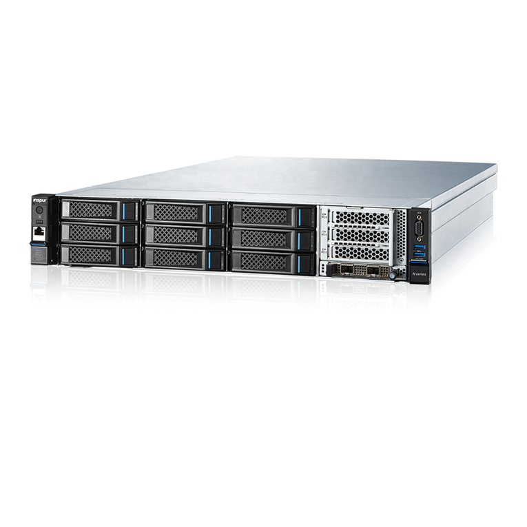
Three-layer drawers with eight 3.5-inch drives in each layer at the front of the
chassis, as shown in the figure below.

6
Figure 2-1 24 × 3.5-inch Drive Configuration
2.2 Features and Specifications
Table 2-1 Features and Specifications
Item Description
Time to Market 2021/06
Form Factor 2U rack server
Processor
One to two Intel®Xeon®Scalable 3300, 4300, 5300, 6300, 8300
Series processor(s):
Up to 40 cores (3.1 GHz)
Max Turbo frequency up to 4.3 GHz (4 cores)
Three UPI links (Up to 11.2 GT/s)
L3 cache up to 1.5 MB (single core)
Thermal design power up to 220 W
Chipset Intel C621A
Integrated
Display
Controller
Integrated in BMC (Aspeed 2600), up to 1280 × 1024
resolution
Memory
Up to 16 memories
Each processor supports 8 memory channels
Each channel supports 1 memory slot
Speed up to 3200 MT/s
Supports RDIMMs and BPS/NVDIMMs

7
Item Description
Memory protection: ECC, memory mirroring, memory
rank sparing
Storage
Front panel:
24 × 3.5-inch hot-swap SATA/SAS drives
Rear storage:
Two-drive chassis supports 2 NVMe drives or 2 SAS/SATA
drives
Four-drive chassis supports 4 NVMe drives, 4 SAS/SATA
drives, 2 NVMe drives + 2 SAS/SATA drives or 8 E1.S SSDs
Eight-drive chassis supports 8 NVMe drives or 4 NVMe
drives + 4 SAS/SATA drives
Two optional SATA M.2 SSDs supporting hardware and
software RAID
Up to 2 TF cards (one for BIOS and the other for BMC)
Storage
Controller
The RAID controller card controls all SAS/SATA drives
NVMe drives can be directly connected to the CPU
Network
One onboard OCP 3.0 NIC module and one scalable OCP
3.0 NIC module (1 Gb/s, 10 Gb/s, 25 Gb/s, 100 Gb/s, 200
Gb/s)
Standard 1 Gb/10 Gb/25 Gb/40 Gb/100 Gb NICs
I/O Expansion
Two-drive chassis: Up to 6 standard PCIe expansion cards
and up to 1 OCP 3.0 NIC
Two PCIe 4.0 x16 half-height half-length cards
Four PCIe 3.0 x8 half-height half-length cards
Four-drive chassis: Up to 4 standard PCIe expansion cards
and up to 2 OCP 3.0 NICs
One PCIe 4.0 x16 half-height half-length card
Three PCIe 3.0 x8 half-height half-length cards
Eight-drive chassis: Up to 2 standard PCIe expansion cards
and up to 1 OCP 3.0 NIC
Two PCIe 3.0 x8 half-height half-length cards

8
Item Description
Port
2 rear USB 3.0 ports
1 rear VGA port
1 COM port
Fan
6 hot-swap and N+1 redundant 6056 fans (High
specification)/6038*(Low-speed).
*6056 fans are equipped by default and 6038 fans can be
selected for different configurations
Power Supply
1+1 redundant power supplies (1300 W/1600 W output
power)
110 VAC - 230 VAC: 90 V - 264 V
240 VDC: 180 V - 320 V
336 VDC: 260 V - 400 V
-48 VDC: -40 V to -72 V
System
Management
Integrated with 1 independent 1000 Mbps network interface,
dedicated for IPMI remote management
Operating
System
Microsoft Windows Server 2016/2019;
Red Hat Enterprise Linux 7/8;
SUSE Linux Enterprise Server 12/15;
CentOS Enterprise Linux 7/8;
Chassis
Dimensions
With mounting ears: 482 × 87.5 × 891.2 mm (18.98 × 3.44
× 35.09 inch) (Width × Height × Depth)
Without mounting ears: 447 × 87.5 × 866 mm (17.60 ×
3.44 × 34.09 inch) (Width × Height × Depth)
Outer Packaging
Dimensions
Length × Width × Height: 1168 × 721 × 279 mm (459.84 ×
283.86 × 109.84 inch)
Weight
24 × 3.5" Configuration:
Net weight: 45 kg (99.2 lb)
Gross weight: 58 kg (127.9 lb) (Packages + Rails +
Accessory Box included)

9
Item Description
Temperature Operating: 5°C - 35°C (41°F - 95°F)
Storage (packed): -40°C to +70°C (-40°F to +158°F)
Storage (unpacked): -40°C to +70°C (-40°F to +158°F)
Humidity Operating: 5% - 90% R.H.
Storage (packed): 5% - 95% R.H.
Storage (unpacked): 5% - 95% R.H.
Altitude
Operating temperature: 5°C - 35°C (41°F - 95°F) at 0 - 914
m (0 - 3000 ft)
Operating temperature: 10°C - 32℃(50°F - 89.6°F) at 914
- 2133 m (3000 - 7000 ft)
Noise Idle: 79 db
Operating: 89 db
2.3 Power Efficiency
Table 2-2 Power Efficiency of Platinum Power Supplies
Rated
Power
@10% Load @20% Load @50% Load @100%
Load
PF@50%
Load
1300 W - 90% 94% 91% 0.98
1600 W
-
90%
94%
91%
0.98
Table 2-3 Power Efficiency of Titanium Power Supplies
Rated
Power @10% Load @20% Load
@50%
Load
@100%
Load
PF@50%
Load
1300 W 90% 94% 96% 91% 0.98

10
3Product Overview
3.1 Front Panel
3.1.1 24 × 3.5-inch Drive Configuration
Figure 3-1 Front Panel of 24 × 3.5-inch Drive Configuration
Item Feature
1 Power Button
2 Top-layer Drive Drawer
3 Mid-layer Drive Drawer
4 Bottom-layer Drive Drawer
5 Quick Release Lever
6 UID/BMC RST button
7 LEDs

11
3.2 Rear Panel
Figure 3-2 Rear Panel
Other manuals for NF5266M6
1
Table of contents
Other Inspur Server manuals

Inspur
Inspur NF5266M5 User manual

Inspur
Inspur NF3180A6 User manual

Inspur
Inspur NF5468A5 User manual

Inspur
Inspur Yingxin User manual

Inspur
Inspur NF5888M5 User manual

Inspur
Inspur NF8480M5 Instruction Manual

Inspur
Inspur Yingxin NP3020M2 User manual

Inspur
Inspur NF5266M5 User manual

Inspur
Inspur NF8380M5 User manual

Inspur
Inspur 3408 Series Instruction sheet

Inspur
Inspur Yingxin User manual

Inspur
Inspur Yingxin User manual

Inspur
Inspur NE5260M5 User manual

Inspur
Inspur i48M6 User manual

Inspur
Inspur NF5180M4 User manual

Inspur
Inspur NF5488M5 User manual

Inspur
Inspur NX8840 User manual

Inspur
Inspur NP5570M4 User manual

Inspur
Inspur NF5466M5 User manual

Inspur
Inspur NF5280M5 User manual