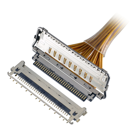
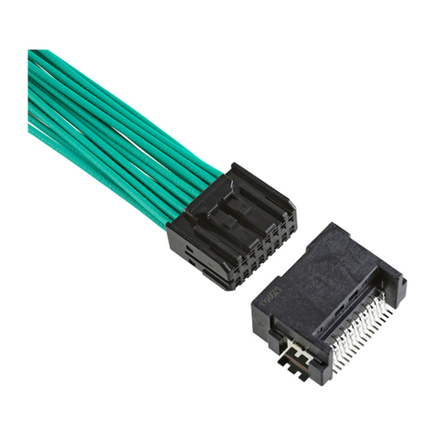
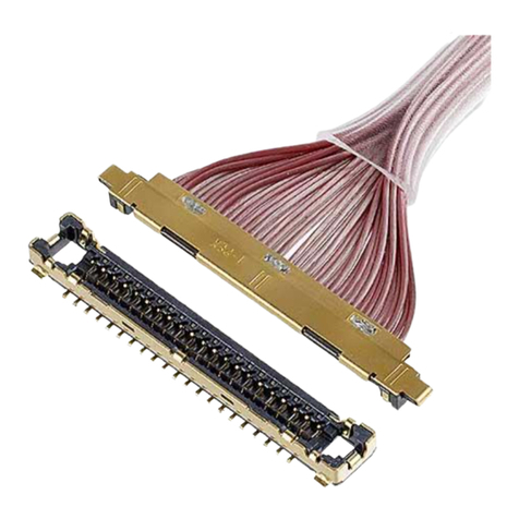
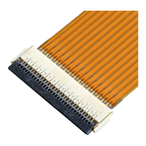
IPEX CABLINE-CBL PLUG User manual

1/ 18
Document No.
ASM
-
09002
Confidential
C
I
-
PEX Inc.
QKE-DFFDE09-04 REV.8
CABLINE®-CBL PLUG
Part No. 20472-#**T-10*
Assembly Manual
3 S15546 November 20, 2015
R.H K.N
2 S15290 July 6, 2015 KNF Tom
1 S12090 February 28, 2012 Y.W E.K
Rev. ECN Date Prepared by Checked by Approved by

CABLINE
-
CBL PLUG
Assembly Manual
Document No.
ASM
-
09002
2/ 18
Confidential
C
1.目的 (Purpose):
CABLINE-CBL PLUG において、ケーブルの半田付け手順及び SHELL A, LATCH BAR の組み付け
について明記する。
This manual is to explain the soldering method / process of the CABLINE-CBL PLUG with cable, and
assembly of SHELL A, LATCH BAR.
2.適用コネクタ (Applicable connector):
Name : CABLINE-CBL PLUG
Parts No. :
Set P/N CABLE ASS’Y 20472-#**T-10*
Discrete P/N
HOUSING ASS’Y 20473-0**T-10*
SHELL A 2618-0**#
LATCH BAR 2619-#**0
3.使用機器等 (Fixtures):
・ パルスヒート (Pulse heater)
・ ヒーターチップ (Heater chip)
加圧力 (Pressure) : 9.8N (1.0kgf)
【Size】板厚 (Thickness) :0.5mm
幅(Width) :(30P) 12.2mm , (40P) 16.2mm
・ 半田バー (Solder bar)
(推奨)φ0.1mm(単芯ヤニ入り半田)の糸半田を使用
(Recommended) φ0.1mm (resin-cored solder) is used.
Positions Length
30P 12.0±0.2
40P 16.0±0.2
・ 半田コテ (Soldering iron): 50W
4.パルスヒート条件[推奨] (Recommended pulse heat condition):
①アイドリング温度 (Idle temp.) 150℃
②1st ヒート設定温度 (1st heat temp.) 220℃
③ 〃 立ち上がり時間 ( 〃 rise time) 0.5sec.
④ 〃 維持時間 ( 〃 holding time) 3.0sec.
⑤2nd ヒート設定温度 (2nd heat temp.) 300℃
⑥ 〃 立ち上がり時間 ( 〃 rise time) 0.5sec.
⑦ 〃 維持時間 ( 〃 holding time) 3.0sec.
1st heat 2nd heat
( ℃)
(sec)
③
④
⑥ ⑦
①
②
⑤

CABLINE
-
CBL PLUG
Assembly Manual
Document No.
ASM
-
09002
3/ 18
Confidential
C
5.作業手順 (Work procedures):
5-1. 芯線の半田付け (Soldering of center-conductor)
①まず適合ケーブルの端末処理形状を下図の様にして下さい。
The cables have to be fabricated as shown below in advance of soldering.
Discrete
AWG#36
SGC.
abc
#40
#4 2
#4 4
0. 09 0
0. 07 5
0. 06 3 0. 18
0.2 0
0. 21
0. 26
0. 28
0. 33
SG C. D im en sio n
PART NO.
20 47 2- 03 0T -1 0
Po s.
30
A
11. 6
0.4
± 0 . 1
A
± 0 . 1
1.55
A+2.0
( 3 ~ 7 )
0.5± 0 . 0 5
0.9± 0.05
0.1 MAX.
( 6 ~ 9 )
A+0.8
± 0 . 1
Cut Line
Laminate Tape
Center Conductor
Soldering Coat
Jacket
Outer Conductor
Insulator
φa
φb
0.46
± 0 . 03
φc
φ0. 15
φ0.25
20 47 2- 04 0T -1 0 40 15. 6
20472
-
030T
-
20
20472
-
0
4
0T
-
20

CABLINE
-
CBL PLUG
Assembly Manual
Document No.
ASM
-
09002
4/ 18
Confidential
C
②コネクタに半田バーをセットする。
Pre-set and locate solder bar at center of connector (HSG ASS’Y).
Fig.1 Set of solder bar
③ケーブルをセットする。
Set the cable.
Fig.2 Set of cable
Solder Bar

CABLINE
-
CBL PLUG
Assembly Manual
Document No.
ASM
-
09002
5/ 18
Confidential
C
④芯線をパルスヒートにて半田付けする。 半田付け状態は、下記 Photo.1 参照。
嵌合側への半田シミだしは 0.15MAX.にて管理願います。 (Photo.1 参照)
Center-conductors are soldered with pulse heater. See photo.1 of soldering condition.
Wicking to the mating side is 0.15MAX. (See photo.1)
Photo.1 AWG#42
※万が一、極間が短絡した場合は、再度パルスヒートにて加熱を行って下さい。
製品にダメージを与える恐れがある為、回数は 1回だけです。
これで短絡が直らない場合は、NG 箇所のみ半田コテにて手修正して下さい。
※When solder bridge is appeared between the terminal, try heating again with pulse heater only one time.
If the bridge isn’t repaired, use the soldering iron only a NG point.
半田コテの種類 (Recommended iron) : UNIX JBC DI 2860 (JAPAN UNIX Co.,Ltd.)
推奨コテ先形状 (Recommended tip shape) : UNIX JBC 2245-036 (JAPAN UNIX Co.,Ltd.)
半田コテの条件 (Condition of Soldering iron) : 50W
半田コテ先温度 (Operating temperature) : 350℃
コテ先当て時間 (Application time of soldering iron) : 5秒以内 (Within 5sec.)
Recommended tip shape (UNIX JBC 2245-036)
Wicking
0.15MAX.
(0.32 Contact Dimple)

CABLINE
-
CBL PLUG
Assembly Manual
Document No.
ASM
-
09002
6/ 18
Confidential
C
5-2. Plug Cover 取り扱い注意事項 (Cautions in treating Plug Cover)
Plug Cover はキャリア付きリール状態にて納品されます。
Plug Cover をキャリアから折り取る手順を明記します。
Plug Cover is delivered in the reel with a career.
The following is the method to cut Plug Cover from Career.
①キャリアを金属用はさみ等を用いて下左写真の Cut Line(緑線)にて切断する。
Cut carrier on the cut line of a lower left picture (green line) by a scissors for metal.
②PLUG COVER の中心部を持ち、±45°の範囲で往復させてノッチ部から切り離します。
もし、切り離れない場合は、この往復動作を繰り返して切り離します。
切り離し後はノッチ折り取り部にバリ発生なきことを確認してください。(写真:5)
Hold the center of Plug cover and bend it 45 deg back and forth to cut it from Notch.
When it does not be cut, try again.
After separated, check there is no burr around the cut part.(Photo.5)
Cut Line
Carrier
Photo
2
. Before cut
Photo
3
.
After
cut
Notch
Photo
4
.
Cut condition
45°
45°

CABLINE
-
CBL PLUG
Assembly Manual
Document No.
ASM
-
09002
7/ 18
Confidential
C
Plug Cover ノッチ部状態(Detail of Notch)
注意:下写真(赤矢印)の様に無理やり引っ張るなどして切り離すとバリや変形の原因になります。
Caution: By pulling like a lower photo to cut off by force (Red arrow direction),
burrs and transformation can be caused.
Photo 6. Bottom side view Photo 7. Upper side view
Photo 8. Cut by force (Bad example)
Photo
5
.
After
cut
View A View B
View A View B
Without burr
Without burr

CABLINE
-
CBL PLUG
Assembly Manual
Document No.
ASM
-
09002
8/ 18
Confidential
C
5-3. Latch Bar 取り扱い注意事項 (Cautions in treating Latch Bar)
Latch Bar はキャリア付きリール状態にて納品されます。
Latch Bar をキャリアから折り取る手順を明記します。
Latch Bar Plug Cover is delivered in the reel with a career.
The following is the method to cut Latch Bar from Career.
①Latch Bar の端部を持ち、±45°の範囲でキャリアを往復させてノッチ部から切り離します。
もし、切り離せない場合は、この往復動作を繰り返して切り離します。
Hold the end of Latch Bar and bend it 45 deg back and forth to cut it from Notch.
When it does not be cut, try again.
Photo 9. Cut condition
②反対側も同様に、Latch Bar の端部を保持しキャリア側を往復させてノッチ部から切り離します。
切り離し後はノッチ折り取り部にバリ発生なきことを確認してください。(写真:12)
Hold the end of Latch Bar and bend it 45 deg back and forth to cut it from Notch.
After separated, check there is no burr around the cut part. (Photo.12)
Photo 10.Cut condition Photo 11.Cut condition(Bad example)
45°
45°

CABLINE
-
CBL PLUG
Assembly Manual
Document No.
ASM
-
09002
9/ 18
Confidential
C
Photo 12. After cut
注意:下写真(赤矢印)の様に無理やり引っ張るなどして切り離すとバリや変形の原因になります。
Caution: By pulling like a lower photo to cut off by force (Red arrow direction),
burrs and transformation can be caused.
Photo 13. Cut by force (Bad example)
Without burr

CABLINE
-
CBL PLUG
Assembly Manual
Document No.
ASM
-
09002
10 / 18
Confidential
C
5-4. LATCH BAR 組み付け (Assembly of LATCH BAR)
Fig.3 の様に LATCH BAR 機構部を HOUSING ASS’Y へ組み付ける。
Latch Bar is placed to specific area on Housing Ass’y. (See Fig.3.)
Fig.3 Assembly of LATCH
※Insulation-tape を必ず付けてください。
※Please make sure to attach Insulation-tape.
Insulation-tape 推奨寸法(Insulation-tape Recommended dimension)
・tape 厚み(tape thickness): 0.05mm
Positions 30P 40P
A 13.0 17.0
Unit:mm
Insulation-tape 推奨寸法(Insulation-tape Recommended dimension)
A
(2.70)
Insulation-tape

CABLINE
-
CBL PLUG
Assembly Manual
Document No.
ASM
-
09002
11 / 18
Confidential
C
5-5. SHELL A 組み付け (Assembly of SHELL A)
①Fig.4 の様にケーブル側から HOUSING のガイド部に沿って SHELL A を組み付ける。
SHELL A is assembled along the guide of HOUSING from the cable side. (See Fig.4.)
Fig.4 Assembly of SHELL A
②SHELL A が正常に組み立てられているか確認する。
SHELL どうしのロックが掛かっているか。(Fig.5★部)
It confirms whether SHELL A is being assembled normally.
Whether SHELL locks are being assembled normally. (Fig.5★point)
Fig.5 The assembly confirmation of SHELL A
Guide
of Housing
A
B
C
★Point
View A
★Point
View C View B

CABLINE
-
CBL PLUG
Assembly Manual
Document No.
ASM
-
09002
12 / 18
Confidential
C
③SHELL A,B とGND BAR をパルスヒートにて半田付けする。 (Fig.6,7◆部)
半田の高さ(半田量)の限度は Fig.7 参照。(製品の全高 0.95mm MAX.)
半田コテの条件は、5頁参照。
当社評価で LVDS アプリケーションには、上シェル 4箇所のみでも対応可能。
SHELL A , B and GND BAR are soldered with the pulse heat. (Fig.6,7◆point)
Refer to Fig.7 for a limit of the solder height. (Connector height: 0.95mm MAX.)
Conditions of Soldering iron: refer to sheet 5.
According to study at IPEX lab, soldering 4points on top shell and 0point on bottom shell is adequate for LVDS
application.
・SHELL A,B 半田付けパルスヒート条件[推奨] (Recommended SHELLA,B pulse heat condition):
①アイドリング温度 (Idle temp.) 150℃
②1st ヒート設定温度 (1st heat temp.) 220℃
③ 〃 立ち上がり時間 ( 〃 rise time) 1.0sec.
④ 〃 維持時間 ( 〃 holding time) 2.0sec.
⑤2nd ヒート設定温度 (2nd heat temp.) 320℃
⑥ 〃 立ち上がり時間 ( 〃 rise time) 1.0sec.
⑦ 〃 維持時間 ( 〃 holding time) 2.0sec.
・ヒーターチップ加圧力[推奨] (Recommended heater TIP Pressure) :8N
< SHELL A >
Fig.6 Soldering of SHELL A and GND BAR
Pulse heat
◆Point
1st heat 2nd heat
( ℃)
(
s
e
c
)
③
④
⑥
⑦
①
②
⑤
solder
S
et the solder

CABLINE
-
CBL PLUG
Assembly Manual
Document No.
ASM
-
09002
13 / 18
Confidential
C
・推奨半田サイズ(Recommended solder size)
板状半田(幅:0.4 mm, 厚み 0.1mm)または φ0.23mm(単芯ヤニ入り半田)の糸半田を潰して使用
A幅の半田を両端(2箇所)の半田付け穴へセットし、B幅の半田を中央(2 箇所)の半田付け穴へセットする。
Platy solder (width:0.4mm, thickness: 0.1mm) is used or φ0.23mm (resin-cored solder) is pressed and used.
Pre-set and locate solder bar of width A at Both of SHELL soldering holes (2 places), and pre-set and locate
solder bar of width B at center of SHELL soldering holes (2 place).
・推奨ヒーターチップ(Recommended Heater chip)
POSITION A B C D
30P 1.0 6.2 7.9 11.9
40P 3.0 8.2 11.9 15.9
A B
Length (mm) 1.4 2.0
D
C
B
A
solder
A(2points)
B(2points)
A
A
0.8
B

CABLINE
-
CBL PLUG
Assembly Manual
Document No.
ASM
-
09002
14 / 18
Confidential
C
< SHELL B >
Fig.7 Soldering of SHELL B and GND BAR
・推奨半田サイズ(Recommended solder size)
板状半田(幅:0.4 mm, 厚み 0.1mm)または φ0.23mm(単芯ヤニ入り半田)の糸半田を潰して使用
A幅の半田を 3箇所の半田付け穴へセットする。
Platy solder (width:0.4mm, thickness: 0.1mm) is used or φ0.23mm (resin-cored solder) is pressed and used.
Pre-set and locate solder bar of width A at SHELL soldering holes (3 places)
A
Length (mm) 2.0
solder
S
et the solder
◆Point
0.25MAX
0.08MAX.
Pulse heat
A(3points)

CABLINE
-
CBL PLUG
Assembly Manual
Document No.
ASM
-
09002
15 / 18
Confidential
C
・推奨ヒーターチップ(Recommended Heater chip)
POSITION A B C
30P 2.6 6.4 11.6
40P
2.6
10.4
15.6
※コネクタに熱をかけ過ぎると、芯線の半田が融解し、芯線が剥離する恐れがあります。
パルスヒート条件の確認を行うようお願いします。
※In case the connector is applied overheat, the solder on cable will melt and solder avulsion will occur.
Please check the pales heat condition and these.
0.8
A
B
C
NG

CABLINE
-
CBL PLUG
Assembly Manual
Document No.
ASM
-
09002
16 / 18
Confidential
C
※SHELL A とSHELLB を半田コテにて半田付けする場合は、下記の手順で行って下さい。
・半田付けの順番は任意です。
・半田コテの条件は、5頁参照。コテ先形状は下記参照。
・半田バーの種類: φ0.2 ㎜(単芯ヤニ入り半田)の糸半田
・半田バーを推奨サイズにカットして、半田付け部分に置き、半田コテを当て半田付けする。
・全ての半田付け部分に半田付けする事。
※When SHELL A and SHELL B are soldered by iron, please follow the procedure in below.
・Soldering order is at random.
・Soldering condition: Refer to 5 sheet. Recommended tip shape is as shown following.
・Solder bar : φ0.2mm (resin-cored solder)
・Cut the recommend solder bar size, and solder by iron after putting solder bar on the shell soldering hole.
・All soldering holes must be soldered.
半田バー推奨サイズ (Recommended solder bar size)
※半田が SHELL 表面に広がり、半田が付かない恐れがあります。
半田付け部分から出ないように半田コテ先を当ててください。
Not soldering is occurred in association with solder extending shell surface.
Please push the soldering iron not to prevent misalignment to the soldering hole.
SHELL A SHELL B
Solder bar φ0.2 φ0.2
Length (mm) A:1.4 B:2.0 1.0
W Recommended tip shape
(UNIX JBC 2245-007)
Solder bar
A
(2points)
B(2points)
*SIZE
Wide : 2mm
T : 0.8mm
T

CABLINE
-
CBL PLUG
Assembly Manual
Document No.
ASM
-
09002
17 / 18
Confidential
C
⑤SHELL A とSHELLB を半田コテにて半田付けする。 (Fig.8◆部)
半田コテの条件は、5頁参照。コテ先形状は下記参照。
半田量は半田はみ出しを注意し、適量を付ける。
SHELL A and SHELL B are soldered by the soldering iron. (Fig.8◆point)
Conditions of Soldering iron refer to sheet 5. Recommended tip shape is as shown following.
Put the appropriate amount of solder, notice the solder protrudes. (See below photo.)
Recommended tip shape (UNIX JBC 2245-036)
Fig.8 Soldering of SHELL A and SHELL B
OK NG
※注意
SHELL A とSHELL B が半田付けされていない場合は、ラッチバー外れの原因となります。
※Attention
There is possibilities to cause Latch bar dropping out from the connector, if Shell A and Shell B are not soldered.
OK
◆
Point
Solder protrudes area
OK
NG
Latch bar 外れ NG
NG: Latch bar
is dropping out.
NG

CABLINE
-
CBL PLUG
Assembly Manual
Document No.
ASM
-
09002
18 / 18
Confidential
C
※半田付け時の注意点
Latch Bar を使用する際は、絶縁テープに半田こてが当たらないようご注意下さい。
半田こての熱によって溶け、RECEPTACLE と嵌合した際にショートする恐れがあります。
※Caution in soldering.
When using Latch-Bar, Please be careful the soldering iron dose not touch to the insulation-tape.
The heat of the soldering iron can melt them and there is possibility to cause short when mating with receptacle.
This manual suits for next models
8
Other IPEX Cables And Connectors manuals
IPEX
IPEX ISH User manual

IPEX
IPEX MINIFLEX 2-BF LK User manual

IPEX
IPEX CABLINE-UM User manual

IPEX
IPEX ISH20P User manual

IPEX
IPEX CABLINE-CX II PLUG Without Cover User manual

IPEX
IPEX CABLINE-VS IIF User manual

IPEX
IPEX MHF 7S User manual

IPEX
IPEX CABLINE-CAL User manual

IPEX
IPEX MHF-TI User manual
IPEX
IPEX MINIFLEX 2-BF User manual

IPEX
IPEX CABLINE-CA II PLUS User manual

IPEX
IPEX CABLINE-VS PLUG User manual

IPEX
IPEX EVAFLEX 5-SE-GHT User manual
IPEX
IPEX MINIFLEX 175-ST User manual

IPEX
IPEX CABLINE-CAF User manual
IPEX
IPEX CABLINE-VSF User manual

IPEX
IPEX ISH VW User manual

IPEX
IPEX AP-10 User manual
IPEX
IPEX CABLINE-CX II With Cover User manual

IPEX
IPEX NOVASTACK 35-HDP User manual