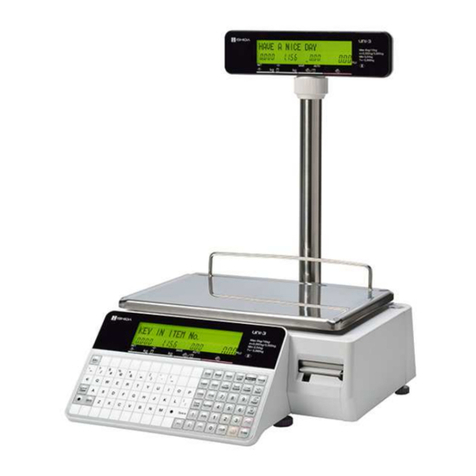
ISHIDA Uni-3 User manual

Ishida Uni-3
Price Computing Scale
With Printer
Technical Manual
PN 166736 Rev B


Contents i
Technical training seminars are available through Rice Lake Weighing Systems.
Course descriptions and dates can be viewed at www.ricelake.com/training
or obtained by calling 715-234-9171 and asking for the training department.
Contents
1.0 Introduction.................................................................................................................................. 1
1.1 Safety . . . . . . . . . . . . . . . . . . . . . . . . . . . . . . . . . . . . . . . . . . . . . . . . . . . . . . . . . . . . . . . . . . . . . 1
1.2 Basic Information . . . . . . . . . . . . . . . . . . . . . . . . . . . . . . . . . . . . . . . . . . . . . . . . . . . . . . . . . . . . 2
1.3 Menu Navigation . . . . . . . . . . . . . . . . . . . . . . . . . . . . . . . . . . . . . . . . . . . . . . . . . . . . . . . . . . . . . 4
1.3.1 Set the Time and Date. . . . . . . . . . . . . . . . . . . . . . . . . . . . . . . . . . . . . . . . . . . . . . . . . . . . . . . . . . 4
1.3.2 Program Store Address . . . . . . . . . . . . . . . . . . . . . . . . . . . . . . . . . . . . . . . . . . . . . . . . . . . . . . . . . 5
1.3.3 Program Price Changes. . . . . . . . . . . . . . . . . . . . . . . . . . . . . . . . . . . . . . . . . . . . . . . . . . . . . . . . . 5
1.3.4 Set Preset Speed Keys . . . . . . . . . . . . . . . . . . . . . . . . . . . . . . . . . . . . . . . . . . . . . . . . . . . . . . . . . 6
1.3.5 Set IP Address of the Scale . . . . . . . . . . . . . . . . . . . . . . . . . . . . . . . . . . . . . . . . . . . . . . . . . . . . . . 6
1.3.6 Set the IP Address of the PC . . . . . . . . . . . . . . . . . . . . . . . . . . . . . . . . . . . . . . . . . . . . . . . . . . . . . 7
1.3.7 Configure Wi-Fi settings. . . . . . . . . . . . . . . . . . . . . . . . . . . . . . . . . . . . . . . . . . . . . . . . . . . . . . . . . 7
1.3.8 Set Label Cassette for Default Label Format . . . . . . . . . . . . . . . . . . . . . . . . . . . . . . . . . . . . . . . . . 8
1.3.9 Load File from Flash Drive . . . . . . . . . . . . . . . . . . . . . . . . . . . . . . . . . . . . . . . . . . . . . . . . . . . . . . . 9
1.3.10 Save File to Flash Drive . . . . . . . . . . . . . . . . . . . . . . . . . . . . . . . . . . . . . . . . . . . . . . . . . . . . . . . . . 9
1.3.11 Set Product Name Display Timer . . . . . . . . . . . . . . . . . . . . . . . . . . . . . . . . . . . . . . . . . . . . . . . . . 10
2.0 Installation ................................................................................................................................. 11
2.1 Installation . . . . . . . . . . . . . . . . . . . . . . . . . . . . . . . . . . . . . . . . . . . . . . . . . . . . . . . . . . . . . . . . . 11
2.1.1 Preliminary Information . . . . . . . . . . . . . . . . . . . . . . . . . . . . . . . . . . . . . . . . . . . . . . . . . . . . . . . . 11
2.1.2 Preliminary Setup Before Delivery . . . . . . . . . . . . . . . . . . . . . . . . . . . . . . . . . . . . . . . . . . . . . . . . 11
2.1.3 At the Customer’s Location–Wireless . . . . . . . . . . . . . . . . . . . . . . . . . . . . . . . . . . . . . . . . . . . . . 12
2.1.4 At the Customer’s Location–Wired . . . . . . . . . . . . . . . . . . . . . . . . . . . . . . . . . . . . . . . . . . . . . . . 12
2.1.5 At the Customer’s Location–Wrap Up . . . . . . . . . . . . . . . . . . . . . . . . . . . . . . . . . . . . . . . . . . . . . 12
2.2 Repair Parts . . . . . . . . . . . . . . . . . . . . . . . . . . . . . . . . . . . . . . . . . . . . . . . . . . . . . . . . . . . . . . . 13
2.3 Block Diagrams. . . . . . . . . . . . . . . . . . . . . . . . . . . . . . . . . . . . . . . . . . . . . . . . . . . . . . . . . . . . . 19
2.3.1 Harness List . . . . . . . . . . . . . . . . . . . . . . . . . . . . . . . . . . . . . . . . . . . . . . . . . . . . . . . . . . . . . . . . 21
2.4 Electric Signals . . . . . . . . . . . . . . . . . . . . . . . . . . . . . . . . . . . . . . . . . . . . . . . . . . . . . . . . . . . . . 22
2.4.1 Main Board . . . . . . . . . . . . . . . . . . . . . . . . . . . . . . . . . . . . . . . . . . . . . . . . . . . . . . . . . . . . . . . . . 22
2.4.2 Key Board PS-068 (Bench/Pole), PS-037 (Hanging) . . . . . . . . . . . . . . . . . . . . . . . . . . . . . . . . . . 23
2.4.3 L1 Type LCD Display Board. . . . . . . . . . . . . . . . . . . . . . . . . . . . . . . . . . . . . . . . . . . . . . . . . . . . . 23
2.4.4 L2 Type LCD Display Board. . . . . . . . . . . . . . . . . . . . . . . . . . . . . . . . . . . . . . . . . . . . . . . . . . . . . 23
2.4.5 Wireless LAN Board (PK-265) . . . . . . . . . . . . . . . . . . . . . . . . . . . . . . . . . . . . . . . . . . . . . . . . . . . 23
2.5 Machine Disassembly . . . . . . . . . . . . . . . . . . . . . . . . . . . . . . . . . . . . . . . . . . . . . . . . . . . . . . . . 24
2.5.1 Bench Type . . . . . . . . . . . . . . . . . . . . . . . . . . . . . . . . . . . . . . . . . . . . . . . . . . . . . . . . . . . . . . . . . 24
2.5.2 Pole Type . . . . . . . . . . . . . . . . . . . . . . . . . . . . . . . . . . . . . . . . . . . . . . . . . . . . . . . . . . . . . . . . . . 30
3.0 Setup Mode ................................................................................................................................ 32
3.1 Enter/Exit Setup Mode . . . . . . . . . . . . . . . . . . . . . . . . . . . . . . . . . . . . . . . . . . . . . . . . . . . . . . . 32
3.2 B01-Machine Number. . . . . . . . . . . . . . . . . . . . . . . . . . . . . . . . . . . . . . . . . . . . . . . . . . . . . . . . 33
3.2.1 Connect Master and Satellite Scales . . . . . . . . . . . . . . . . . . . . . . . . . . . . . . . . . . . . . . . . . . . . . . 34
3.3 B02-Sales Mode . . . . . . . . . . . . . . . . . . . . . . . . . . . . . . . . . . . . . . . . . . . . . . . . . . . . . . . . . . . . 35
3.4 B03-Password . . . . . . . . . . . . . . . . . . . . . . . . . . . . . . . . . . . . . . . . . . . . . . . . . . . . . . . . . . . . . 36
3.5 B05-Data Storage . . . . . . . . . . . . . . . . . . . . . . . . . . . . . . . . . . . . . . . . . . . . . . . . . . . . . . . . . . . 37
3.6 B06-Preset Report . . . . . . . . . . . . . . . . . . . . . . . . . . . . . . . . . . . . . . . . . . . . . . . . . . . . . . . . . . 38
3.7 B07-PLU Overwrite . . . . . . . . . . . . . . . . . . . . . . . . . . . . . . . . . . . . . . . . . . . . . . . . . . . . . . . . . . 40
3.8 B08-PLU Initial Data . . . . . . . . . . . . . . . . . . . . . . . . . . . . . . . . . . . . . . . . . . . . . . . . . . . . . . . . . 41
3.9 B10-Receipt Setting . . . . . . . . . . . . . . . . . . . . . . . . . . . . . . . . . . . . . . . . . . . . . . . . . . . . . . . . . 44
3.10 B11-Cassette . . . . . . . . . . . . . . . . . . . . . . . . . . . . . . . . . . . . . . . . . . . . . . . . . . . . . . . . . . . . . . 46
© Rice Lake Weighing Systems. All rights reserved. Printed in the United States of America.
Specifications subject to change without notice.
Rice Lake Weighing Systems is an ISO 9001 registered company.
February 29, 2016

ii Uni-3 Technical Manual
3.11 B12-Label Specifications. . . . . . . . . . . . . . . . . . . . . . . . . . . . . . . . . . . . . . . . . . . . . . . . . . . . . . 47
3.12 B13-Label Format . . . . . . . . . . . . . . . . . . . . . . . . . . . . . . . . . . . . . . . . . . . . . . . . . . . . . . . . . . . 48
3.13 B14-Barcode . . . . . . . . . . . . . . . . . . . . . . . . . . . . . . . . . . . . . . . . . . . . . . . . . . . . . . . . . . . . . . 49
3.14 B17-Operation Setting . . . . . . . . . . . . . . . . . . . . . . . . . . . . . . . . . . . . . . . . . . . . . . . . . . . . . . . 52
3.15 B18-Error Process . . . . . . . . . . . . . . . . . . . . . . . . . . . . . . . . . . . . . . . . . . . . . . . . . . . . . . . . . . 54
3.16 B20-Traceability . . . . . . . . . . . . . . . . . . . . . . . . . . . . . . . . . . . . . . . . . . . . . . . . . . . . . . . . . . . . 55
3.17 B21-Dual Currency . . . . . . . . . . . . . . . . . . . . . . . . . . . . . . . . . . . . . . . . . . . . . . . . . . . . . . . . . . 55
3.18 B22-Price Rounding . . . . . . . . . . . . . . . . . . . . . . . . . . . . . . . . . . . . . . . . . . . . . . . . . . . . . . . . . 56
3.19 B23-Frequent Shopper . . . . . . . . . . . . . . . . . . . . . . . . . . . . . . . . . . . . . . . . . . . . . . . . . . . . . . . 56
3.20 B26-Country . . . . . . . . . . . . . . . . . . . . . . . . . . . . . . . . . . . . . . . . . . . . . . . . . . . . . . . . . . . . . . . 57
3.21 B27-File Save/Load. . . . . . . . . . . . . . . . . . . . . . . . . . . . . . . . . . . . . . . . . . . . . . . . . . . . . . . . . . 60
3.22 B28-Data Distribution . . . . . . . . . . . . . . . . . . . . . . . . . . . . . . . . . . . . . . . . . . . . . . . . . . . . . . . . 61
3.23 B29-Tax . . . . . . . . . . . . . . . . . . . . . . . . . . . . . . . . . . . . . . . . . . . . . . . . . . . . . . . . . . . . . . . . . . 62
3.24 B31-Mode Access Code. . . . . . . . . . . . . . . . . . . . . . . . . . . . . . . . . . . . . . . . . . . . . . . . . . . . . . 63
4.0 Adjustment Mode....................................................................................................................... 64
4.1 Enter Adjustment Mode. . . . . . . . . . . . . . . . . . . . . . . . . . . . . . . . . . . . . . . . . . . . . . . . . . . . . . . 64
4.2 C01-Date Time . . . . . . . . . . . . . . . . . . . . . . . . . . . . . . . . . . . . . . . . . . . . . . . . . . . . . . . . . . . . . 65
4.3 C03-Display Check . . . . . . . . . . . . . . . . . . . . . . . . . . . . . . . . . . . . . . . . . . . . . . . . . . . . . . . . . . 65
4.4 C04-Key Check . . . . . . . . . . . . . . . . . . . . . . . . . . . . . . . . . . . . . . . . . . . . . . . . . . . . . . . . . . . . 65
4.5 C05-Firmware Details . . . . . . . . . . . . . . . . . . . . . . . . . . . . . . . . . . . . . . . . . . . . . . . . . . . . . . . . 66
4.6 C06-Memory Clear . . . . . . . . . . . . . . . . . . . . . . . . . . . . . . . . . . . . . . . . . . . . . . . . . . . . . . . . . . 66
4.7 C07-Printer . . . . . . . . . . . . . . . . . . . . . . . . . . . . . . . . . . . . . . . . . . . . . . . . . . . . . . . . . . . . . . . . 67
4.8 C08-Calibration. . . . . . . . . . . . . . . . . . . . . . . . . . . . . . . . . . . . . . . . . . . . . . . . . . . . . . . . . . . . . 68
4.8.1 Calibrate the Scale. . . . . . . . . . . . . . . . . . . . . . . . . . . . . . . . . . . . . . . . . . . . . . . . . . . . . . . . . . . . 68
4.9 C10-Download . . . . . . . . . . . . . . . . . . . . . . . . . . . . . . . . . . . . . . . . . . . . . . . . . . . . . . . . . . . . . 69
4.10 C11-Option Check . . . . . . . . . . . . . . . . . . . . . . . . . . . . . . . . . . . . . . . . . . . . . . . . . . . . . . . . . . 70
4.11 C13-Model . . . . . . . . . . . . . . . . . . . . . . . . . . . . . . . . . . . . . . . . . . . . . . . . . . . . . . . . . . . . . . . . 70
5.0 Program Mode ........................................................................................................................... 71
5.1 P01-PLU Data. . . . . . . . . . . . . . . . . . . . . . . . . . . . . . . . . . . . . . . . . . . . . . . . . . . . . . . . . . . . . . 72
5.2 P02-Campaign . . . . . . . . . . . . . . . . . . . . . . . . . . . . . . . . . . . . . . . . . . . . . . . . . . . . . . . . . . . . . 75
5.3 P03-Operators . . . . . . . . . . . . . . . . . . . . . . . . . . . . . . . . . . . . . . . . . . . . . . . . . . . . . . . . . . . . . 75
5.4 P04-Preset Key Registration . . . . . . . . . . . . . . . . . . . . . . . . . . . . . . . . . . . . . . . . . . . . . . . . . . . 76
5.5 P05-Ad Message . . . . . . . . . . . . . . . . . . . . . . . . . . . . . . . . . . . . . . . . . . . . . . . . . . . . . . . . . . . 78
5.6 P06-Store Data . . . . . . . . . . . . . . . . . . . . . . . . . . . . . . . . . . . . . . . . . . . . . . . . . . . . . . . . . . . . . 78
5.7 P07-Department . . . . . . . . . . . . . . . . . . . . . . . . . . . . . . . . . . . . . . . . . . . . . . . . . . . . . . . . . . . . 78
5.8 P08-Group . . . . . . . . . . . . . . . . . . . . . . . . . . . . . . . . . . . . . . . . . . . . . . . . . . . . . . . . . . . . . . . . 79
5.9 P09-Cooking Time . . . . . . . . . . . . . . . . . . . . . . . . . . . . . . . . . . . . . . . . . . . . . . . . . . . . . . . . . . 79
5.10 P10-Nutrition. . . . . . . . . . . . . . . . . . . . . . . . . . . . . . . . . . . . . . . . . . . . . . . . . . . . . . . . . . . . . . . 79
5.11 P11-P13 Extra Message Data 1-3. . . . . . . . . . . . . . . . . . . . . . . . . . . . . . . . . . . . . . . . . . . . . . . 80
5.12 P14-Coupon Message . . . . . . . . . . . . . . . . . . . . . . . . . . . . . . . . . . . . . . . . . . . . . . . . . . . . . . . 81
5.13 P15-POP Message . . . . . . . . . . . . . . . . . . . . . . . . . . . . . . . . . . . . . . . . . . . . . . . . . . . . . . . . . . 81
5.14 P19-Lookup Table . . . . . . . . . . . . . . . . . . . . . . . . . . . . . . . . . . . . . . . . . . . . . . . . . . . . . . . . . . 81
5.15 P21-Fix Price Symbol . . . . . . . . . . . . . . . . . . . . . . . . . . . . . . . . . . . . . . . . . . . . . . . . . . . . . . . . 82
5.16 P22-P36 Free Message 1-15 . . . . . . . . . . . . . . . . . . . . . . . . . . . . . . . . . . . . . . . . . . . . . . . . . . 82
5.17 P37-Check Label . . . . . . . . . . . . . . . . . . . . . . . . . . . . . . . . . . . . . . . . . . . . . . . . . . . . . . . . . . . 82
5.18 P38-Stamp Price Data . . . . . . . . . . . . . . . . . . . . . . . . . . . . . . . . . . . . . . . . . . . . . . . . . . . . . . . 82
6.0 Appendix .................................................................................................................................... 83
6.1 Error Codes . . . . . . . . . . . . . . . . . . . . . . . . . . . . . . . . . . . . . . . . . . . . . . . . . . . . . . . . . . . . . . . 83
6.2 Text Editing . . . . . . . . . . . . . . . . . . . . . . . . . . . . . . . . . . . . . . . . . . . . . . . . . . . . . . . . . . . . . . . . 85
6.3 Specifications . . . . . . . . . . . . . . . . . . . . . . . . . . . . . . . . . . . . . . . . . . . . . . . . . . . . . . . . . . . . . . 86
Rice Lake continually offers web-based video training on a growing selection
of product-related topics at no cost. Visit www.ricelake.com/webinars

Introduction 1
1.0 Introduction
This manual is intended for use by service technicians responsible for installing and servicing Uni-3 counter top scales.
Authorized distributors and their employees can view or download this manual from the Rice Lake
Weighing Systems website at www.ricelake.com/retail.
An Operation Manual is included with the scale and provides basic operating instructions for users of the Uni-3.
Please leave the Operation Manual with the scale when installation and configuration are complete.
1.1 Saf e t y
This scale is manufactured for use according to proper procedures by a qualified person and only for the purposes
described in this manual. Always heed the information provided in this manual. Failure to heed precautions can
result in personal injury or property damage.
Safety Symbol Definitions
Indicates a potentially hazardous situation that, if not avoided, could result in serious injury or death, and
includes hazards that are exposed when guards are removed.
Indicates a potentially hazardous situation that, if not avoided, may result in minor or moderate injury.
Indicates information about procedures that, if not observed, could result in damage to equipment or
corruption to and loss of data.
Safety Precautions
Do not operate or work on this equipment unless you have read and understand the instructions and
warnings in this Manual. Failure to follow the instructions or heed the warnings could result in injury or
death. Rice Lake Weighing Systems is not liable for any damage, loss or injury that results from
incorrect operation, insufficient caution, unauthorized modifications to the scale, or failure to follow the
instructions contained in this manual. Contact any Rice Lake Weighing Systems dealer for replacement
manuals. Proper care is your responsibility.
Some procedures described in this manual require work inside the indicator enclosure. These procedures
are to be performed by qualified service personnel only.
General Safety
Failure to heed may result in serious injury or death.
Do not allow minors (children) or inexperienced persons to operate this unit.
Do not operate without all shields and guards in place.
Do not use for purposes other than weight taking.
Do not place fingers into slots or possible pinch points.
Do not use any load-bearing component that is worn beyond five percent of the original dimension.
Do not use this product if any of the components are cracked.
Do not exceed the rated load limit of the unit.
Do not make alterations or modifications to the unit.
Do not remove or obscure warning labels.
Before opening the unit, ensure the power cord is disconnected from the outlet.
Do not allow water or any liquids to come into contact with the scale.
Do not drop or apply shock to the scale.
Do not disassemble, modify or attempt to repair the scale.
Do not hold the connector cover when carrying the scale.
Do not hold the operation panel or weigh platter when carrying the scale.
Do not hold the customer display when carrying the scale.
Dispose of batteries according to local regulations.
Handle with care when removing or inserting the cassette.
WARNING
CAUTION
Important
WARNING
WARNING

2Uni-3 Technical Manual
1.2 Basic Information
Figure 1-1. Uni-3 Outer Dimensions for Bench Type
Figure 1-2. Outer Dimensions for Hanging Type
410 mm
16.1 in
370 mm
14.6 in
266 mm
10.5 in
159 mm
6.5 in
437 mm
17.2 in
420 mm
16.5 in
800 mm
31.5 in
678 mm
26.7 in
360 mm
14.2 in
146 mm
5.7 in

Introduction 3
Figure 1-3. Outer Dimensions for Pole Type
370 mm
14.6 in
266 mm
10.5 in
437 mm
17.2 in
159 mm
6.3 in
524 mm
20.6 in
500 mm
19.7 in

4Uni-3 Technical Manual
1.3 Menu Navigation
Enter the Mode number and press the Mode key to enter any mode. Some functions in the Setup and Adjustment
modes are restricted to authorized service personnel. Enter the service password 495344 and press PLU to access all
mode steps. All mode steps will then be available until the scale returns to normal operation mode. To exit any
mode, press the Mode key.
Use the Up and Down arrow keys to select a parameter within the menu. Press the Enter key to enter the parameter.
Use the Up and Down arrow keys to move through the menu options. Use the Left and Right arrow keys to scroll
through the choices of each parameter. Enter the choice number and press Enter to select the desired choice.
All menu options may not be available depending on what settings are selected.
Table 1-1. Menu Navigation
1.3.1 Set the Time and Date
Use the following steps to set the time and date.
1. Remove the Speed Key Insert page.
2. Enter 4000 then press Mode. C00 ADJUST will display.
3. Press the Down Arrow. C01 DATE TIME will display.
4. Press Enter. C01-01 DATE will display.
5. Enter the date in a MMDDYYYY format.
Example: For June 21, 2015, enter 06212015.
6. Press Enter twice. C01-2 TIME will display.
7. Enter the time in a HHMMSS format.
Example: For 1:10:00 pm, enter 131000 (time is entered in 24 hour format).
Setup
6000
Adjustment
4000
Operation
2000
Total
8000
Program
9000
B01
Machine No.(comms)
C01 Date/Time S01 Sales F01 Sales Daily Total P01 PLU
B02 Sales Mode C03 Display Check S06 Total Adjust F02 Sales Weekly Total P02 Campaign
B03 Password C04 Key Check S07 POS Function F03 Sales Cumulative Total P03 Operators
B05 Data Storage C05 Firmware Details F05 Product Daily Total P04 Preset Keys
B06 Preset Report C06 Memory Clear F06 Product Weekly Total P05 Ad Message
B07 PLU Overwrite C07 Printer F07 Product Cumulative Total P06 Store
B08 PLU Initial Data C08 Calibration F09 Preset Report P07 Department
B10 Receipt Setting C10 Download F10 POS Report P08 Group
B11 Cassette C11 Option Check F11 Drawer Report P09 Cook Time
B12 Label Spec C13 Model F12 Total Clear P10 Nutrition
B13 Label Format
P11-P13
Extra Message 1-3
B14 Barcode P14 Coupon Message
B17 Operation Setting P15 POP message
B18 Error Process P19 Lookup Table
B20 Traceability P21 Fix Price Symbol
B21 Dual Currency
P22-P36
Free Message 1-15
B22 Price Rounding P37 Check Label
B23
Frequent Shopper
P38 Stamp Price
B26 Country
B27 File Save/Load
B28 Data Distribution
B29 Tax
B31 Mode Code
Note

Introduction 5
8. Press Enter twice. C01-03 LOCAL YEAR displays.
9. Press Mode. 1801-0000 CHECKING CLOCK SETTING will display.
10. Press Enter. C01 DATE TIME will display.
11. Press Mode twice to exit Adjustment Mode. KEY IN ITEM No. will display. Scale is ready to resume
weighing and labeling.
1.3.2 Program Store Address
Use the following steps to enter store information.
1. Remove the Speed Key Insert page.
2. Enter 9000 then press Mode. P00 PROGRAM will display.
3. Press 6then press the Down Arrow. P06 STORE will display.
4. Press Enter. P06-00 no.XXXX will display.
5. Enter Store Number then press PLU. 13001-0000 SET UP NEW DATA will display.
If store information has been programmed it will display. If necessary, store information may be edited by
pressing Edit. To delete any existing text, press Line Delete.
6. Press Enter. InP 0001-0000 00 0001 will display.
7. Type the store name then press Enter. 19001-0000 IS IT OK TO SAVE will display.
8. Press Enter. P06-00 no. XXXX will display.
9. Press 2then press the Down Arrow. P06-02 ADDRESS will display.
10. Press Edit. InP 0001-0000 07 0001 will display.
11. Type the store address then press Enter. InP 19001-0000 IS IT OK TO SAVE will display.
12. Press Enter. P06-00 no.XXXX will display.
13. Press 4then press the Down Arrow. P06-04 PRINTER 1 will display.
14. Enter Store Number entered in step 5. Press
Enter
twice to assign programmed store.
P06-00 no.XXXX
will display.
15. Press Mode three times to exit the Program Mode. KEY IN ITEM No. will display. Scale is ready to resume
weighing and labeling.
1.3.3 Program Price Changes
Use the following steps to change prices for existing items.
1. Remove the Speed Key Insert page.
2. Enter 9000 then press Mode. P00 Program will display.
3. Press 1then press Enter twice. P01-00 PLU will display.
4. Enter the PLU number to be changed, then press PLU.
5. Press 4then press the Down Arrow. P01-01-04 UNIT PRICE will display.
6. Enter the new price and press Enter. P01-01-04 UNIT PRICE and the new price will display.
7. Repeat steps 4 - 6 until all price changes have been made.
8. Press Mode. 19001-0000 IS IT OK TO SAVE will display.
9. Press Enter. P01-00 will display.
10. Press Mode three times to exit Program Mode. KEY IN ITEM No. will display. Scale is ready to resume
weighing and labeling.
Note

6Uni-3 Technical Manual
1.3.4 Set Preset Speed Keys
Use the following steps to set up preset speed keys and function keys.
1. Remove the Speed Key Insert page.
2. Enter 9000 then press Mode. P00 PROGRAM will display.
3. Press 4then press the Down Arrow. P04 PRESET KEY will display.
4. Press Enter. P04-01 0 000 will display.
5. Enter the appropriate Key Flag No. from the list below, then press the PLU key (see Table 2).
6. If the key type requires a specific value such as PLU No. or Tare, enter the number. Otherwise, enter 0.
7. Press desired speed key. The Key Flag No., key position number and key data value are displayed.
8. Repeat steps 5-7 for all preset speed keys.
9. Press Mode three times to exit Program Mode. KEY IN ITEM No. will display. Scale is ready to resume
weighing and labeling.
Table 2. Common Key Flag Parameters
To add a new PLU, see Section 5.1, P01-PLU Data.
1.3.5 Set IP Address of the Scale
Use the following steps to set IP address of the scale.
1. Remove Speed Key insert page.
2. Enter 6000 then press Mode. B00 SETUP will display.
3. Enter the password 495344 then press PLU to enter service level. B00 SETUP will display.
4. Press 1then press Enter twice. B01-01 BASIC will display.
5. Press the Right Arrow, then press Enter. B01-02-01 will display.
6. Enter the IP address, then press Enter. B01-02-01 will display.
Use leading zeros instead of decimals.
Example: enter 192168004025 for 192.168.4.25
7. Press the Down Arrow. B01-02-02 will display.
8. Enter the Subnet Mask then press Enter. B01-02-02 will display.
Example: enter 255255255000 for 255.255.255.0
9. Press the Down Arrow. B01-02-03 will display.
10. Enter the Gateway then press Enter.
Example: enter 192168004001 for 192.168.4.1
Set the Gateway as 0.0.0.0 if not required.
Key Flag No. Parameter
1PLU
2TARE
3 FIXED PRICE
4 X MULTIPLY
8SAVE
11 COUPON MSG
16 EXTRA MSG 1
17 EXTRA MSG 2
18 EXTRA MSG 3
22 LABEL FORMAT
23 IMAGE 1
24 IMAGE 2
26 PEEL MODE
27 LABEL BATCH
32 UNIT PRICE
Key Flag No. Parameter
33 PACK DATE
34 SELL BY DATE
72 CASE WEIGHT
75 AUTO/MANUAL MODE
137 PRINT QTY
156 LOWER PRESET
162 ENTER FIXED WEIGHT
435 CASSETTE SWITCH
Key Flag No. Parameter
Note
Note
Note

Introduction 7
11. Press Mode. 14034-0000 REBOOTING CHECK will display.
12. Press Enter. 15029-0001 RE-BOOT CHECK will display.
13. Power off the scale. Wait 10 seconds before proceeding.
14. Power on the scale. After rebooting, PLEASE CONFIRM TIME will display.
15. Press Enter. KEY IN ITEM No. will display. Scale is ready to resume weighing and labeling.
1.3.6 Set the IP Address of the PC
Use the following steps to set the IP address of the PC.
1. Remove Speed Key insert page.
2. Enter 6000 then press Mode. B00 SETUP will display.
3. Enter the password 495344 then press PLU to enter service level. B00 SETUP will display.
4. Press 1then press Enter twice. B01-01 BASIC will display.
5. Enter 2then press the Right Arrow. B01-03 PC COM will display.
6. Press the Down Arrow. B01-03-01 will display.
7. Enter the PC IP address then press Enter. B01-03-01 and entered IPAddress will display.
8. Press the Down Arrow twice. B01-03-03 COM CHK will display.
9. Enter a number between 30 and 9999. Press Enter. B01-03-03 COM CHK and entered number will display.
A value of 600 is recommended.
10. Press 8then press Down Arrow. B01-03-08 PING TO PC displays.
11. Press Zero to execute PING to test connection to PC. If ping is successful, there will be one long beep. If
ping is unsuccessful, there will be five short beeps.
12. Press Mode three times to exit Setup Mode. KEY IN ITEM No. will display. Scale is ready to resume weighing
and labeling
1.3.7 Configure Wi-Fi settings
Use the following steps to configure the Wi-Fi settings.
1. Remove Speed Key insert page.
2. Enter 6000 then press Mode. B00 SETUP will display.
3. Enter the password 495344 then press PLU to enter service level. B00 SETUP will display.
4. Press Enter twice. B01-01 BASIC is displayed.
5. Press 3then press the Right Arrow. B01-04 WI-FI is displayed.
6. Press Enter. B01-04-01 SECURITY is displayed.
7. Enter a number 1-9 to set the encryption type then press Enter. B01-04-01 SECURITY is displayed.
Table 2. Encryption Options
8. Press the Down Arrow. B01-04-02 Key Type is displayed.
Note
Option Encryption Type
1NONE
2WEP64
3WEP128
4 WEP64 Shared Key
5 WEP128 Shared Key
6WPAPSKTKIP
7WPAPSKCCMP
8 WPA2 PSK TKIP
9WPA2PSKCCMP
Option Encryption Type

8Uni-3 Technical Manual
Key Type is available only when options 2-9 are selected in step 7.
9. Enter a number 1-3 to set the key type, then press Enter. B01-04-02 Key Type is displayed.
10. Press the Down Arrow. B01-04-03 SSID is displayed.
11. Press Edit. Enter wireless network name. This is case sensitive.
12. Press Enter twice. B01-04 WI-FI is displayed.
Steps 13-14 are available only when Key type is set as WEP. If Key Type is not set to WEP, skip to step 15.
13. Press Enter four times. B01-04-04 WEP KEY IND is displayed.
14. Enter a number 1-4 to set the WEP key index, then press Enter. B01-04-05 ENCRYPTION KEY is displayed.
Table 4. WEP Key Index Parameters
The Encryption Key name in step B01-04-05 varies based on the Security Type selected in step 7.
15. Press Edit. Enter the encryption key (case sensitive).
16. Press Enter twice. B01-04 WI-FI is displayed.
17. Press Mode. 14038-0009 WI-FI SET UP is displayed. Wait 5 seconds before proceeding.
18. Press Enter. 14038-0010 WI-FI SET UP is displayed. Wait 5 seconds before proceeding.
19. Press Enter. B01-04 WI-FI is displayed. Wait 5 seconds before proceeding.
20. Press Mode. 14034-0000 REBOOTING CHECK is displayed. Wait 5 seconds before proceeding.
21. Press Enter. 15029-0001 REBOOT CHECK is displayed. Wait 5 seconds before proceeding.
22. Power off the scale. Wait 10 seconds before proceeding.
23. Power on the scale. After rebooting, PLEASE CONFIRM TIME will display.
24. Press Enter. KEY IN ITEM No. will display
25. Confirm communication. Scale is ready to resume weighing and labeling.
Number Encryption Key Type
1Hex
2ASCII
3 Passphrase
Table 3. Encryption Key Types
Number WEP Key Index
1Key1
2Key2
3Key3
4Key4
Note
Note
Note

Introduction 9
1.3.8 Set Label Cassette for Default Label Format
Use the following steps to set label cassette for the default label format.
1. Remove Speed Key insert page.
2. Enter 6000 then press Mode. B00 SETUP will display.
3. Enter the password 495344 then press PLU to enter service level. B00 SETUP will display.
4. Press 11 then press the Down Arrow, then press Enter.B11-01 CASSETTE No.will display.
5. Press 4then press the Down Arrow. B11-04 FMT No. will display.
6. Enter the desired default label format number. Press Enter. B11-04 FMT No. with number will display.
7. Press 8then press the Down Arrow. B11-08 PRN MODE will display.
8. Enter 0for Manual or 1for Auto. Press Enter twice. B11-09 LBL TYPE will display.
9. Enter 0for Die Cut or 1for Continuous. Press Enter.
10. Enter 17 then press the Down Arrow. B11-17 PLU NAME will display.
11. Enter 0for Fixed or 1for Variable. Press Enter twice. B11-18 XTRAMSG1 will display.
12. Enter 0for Fixed or 1for Variable. Press Enter twice. B11-19 XTRAMSG2 will display.
13. Enter 0for Fixed or 1for Variable. Press Enter twice.B11-20 XTRAMSG3 will display.
14. Enter 0for Fixed or 1for Variable. Press Enter. B11-20 XTRAMSG3 will display.
When using continuous labels, settings B11-17 through B11-20 should be set to 1 for Variable.
15. Press Mode three times Setup Mode. KEY IN ITEM No. will display. The scale is ready to resume weighing
and labeling.
1.3.9 Load File from Flash Drive
USB specfications: 8 GB or smaller, FAT32 format, USB 3.0
Use the following steps to load files from a flash drive.
1. Remove Speed Key insert page.
2. Insert a flash drive containing a DATA0x Folder.
3. Enter 6000 then press Mode. B00 SETUP will display.
4. Enter the password 495344 then press PLU to enter service level. B00 SETUP will display.
5. Enter 27 then press the Down Arrow. B27 FILE SAVE/LOAD will display.
6. Press Enter twice. B21-01-01 I/P SELECT will display.
7. Press PLU. B27-100 SEL USB FOLDER will display. This may take up to 30 seconds as files are scanned.
8. Press the Down Arrow to locate file to be loaded. B27-10x and File Name will display.
9. Press PLU to select file. B27-01 USB-TO-SCALE will display.
10. Press the Down Arrow twice. B27-01-03 MASTER MODE will display.
11. Press 1for Auto or press 2for Manual load. Press Enter. B27-01-03 MASTER MODE with selected load choice
will display.
12. Press Enter. B27-01-04 EXECUTE will display.
13. Press Zero. 14011-0000 INPUT CHEECK will display.
14. Press Enter to begin loading files. 14013-0000 COMPLETE INPUT will display when complete.
15. Press Enter then press Mode three times to exit Setup Mode. KEY IN ITEM No. will display.
16. Remove the flash drive. Scale is ready to resume weighing and labeling.
Note
Note

10 Uni-3 Technical Manual
1.3.10 Save File to Flash Drive
USB specifications: 8GB or smaller, FAT32 format, USB 3.0
Use the following steps to save files to a flash drive.
1. Remove Speed Key insert page.
2. Insert a flash drive.
3. Enter 6000 then press Mode. B00 SETUP will display.
4. Enter the password 495344 then press PLU to enter service level. B00 SETUP will display.
5. Enter 27 then press the Down Arrow, then press Enter. B27-01 USB-TO-SCALE will display.
6. Press the Right Arrow then press Enter. B27-02-01 O/P SELECT will display.
7. Press PLU. B27-200 SEL USB FOLDER will display.
8. Press the Down Arrow to select an empty folder. B27-20x USB DATA 0x will display.
9. Press Edit to name folder. InP 0001 will display.
10. Type in folder name. Press Enter. B27-02 SCALE-TO-USB will display.
11. Press 3then press the Down Arrow. B27-02-03 MASTER MODE will display.
12. Enter 1for Auto or 2for Manual send. Press Enter. B27-02-03 Master Mode (with selected load choice) will
display.
13. Press Enter. B27-02-04 EXECUTE will display.
14. Press Zero. 14012-0000 OUTPUT CHECK will display.
15. Press Enter to begin sending file to USB. 14014-0000 COMPLETE will display when complete.
16. Press Enter then press Mode three times to exit Setup Mode. KEY IN ITEM No. will display.
17. Remove the flash drive. Scale is ready to resume weighing and labeling.
1.3.11 Set Product Name Display Timer
Use the following steps to set the product name display timer.
1. Remove Speed Key insert page.
2. Enter 6000 then press Mode. B00 SETUP will display.
3. Enter the password 495344 then press PLU to enter service level. B00 SETUP will display.
4. Enter 17 then press the Down Arrow then press Enter twice. B17-01-02 OPEN PLU will display.
5. Enter 4then press the Down Arrow. B17-01-05 SEG PLU will display.
6. Enter 2then press Enter three times. B17-01 CALL will display.
7. Enter 2then press the Right Arrow, then press Enter. B17-03-01 REG TMR will display.
8. Enter 4then press the Down Arrow. B17-03-07 SEG PLU TIMER will display.
9. Enter 3then press Enter. B17-03-07 SEG PLU TIMER will display.
10. Press Mode three times to exit Setup Mode. KEY IN ITEM No. will display. Scale is ready to resume
weighing and labeling.
Note

Installation 11
2.0 Installation
Ensure the user has read and understands the Safety section of this manual.
• Always use a power supply with rated voltage. Never connect the scale power input with an AC power supply
exceeding the rated voltage. To avoid any potential electrical shock, ensure that the protective ground wire is
connected to the main grounding provision. Using the scale outside of the rated voltage may result in machine
failure or danger such as electric shock.
• Prepare a dedicated power source. A power supply that generates voltage variation may cause a malfunction.
• Do not stand or place anything heavy on the power cord, doing so may damage the cord.
• Disconnect power supply before servicing.
• Take precaution against residual electrical charge hazard. Capacitors inside the scale may still hold an electrical
charge even after power is disconnected.
• Do not remove covers or enclosures.
• Do not perform unspecified maintenance.
Do not install the scale in the following types of places:
• Subject to high temperatures or high humidity
• Exposed to direct sunlight
• Where water or other liquids are easily spilled on the scale
• Subject to excessive vibration or unstable foundations
• Exposed to direct cold air from air conditioners or refrigerators
• Where the floor or foundation is unstable
• Subject to a lot of dust or dirt
• With large voltage fluctuations
2.1 Installation
The following is an overview of the installation procedure of the Ishida Uni-3 scale.
2.1.1 Preliminary Information
1. Determine the IP address(es) to be assigned to the scale(s).
2. Determine the wireless information (optional).
2.1.2 Preliminary Setup Before Delivery
1. Remove the scale from the box.
2. Assemble the scale.
For pole models, place any excess cable inside the pole—not the scale body.
3. Check the firmware version, see Section 4.5 on page 66.
4. If necessary, upgrade the firmware.
• Power up the scale with USB stick installed, loaded with appropriate “soft” firmware folder.
5. Clear the scale’s memory, see Section 4.6 on page 66.
6. Configure the country, see Section 3.20 on page 57.
7. Set the date and time, see Section 4.2 on page 65.
8. Program the IPAddress, Subnet Mask, etc., see Section 3.2 on page 33.
9. Program the wireless settings, see Section 3.2 on page 33.
10. Verify scale communication using the Ping command and SLP-5.
11. Load labels.
12. Load backup file from USB (see Section 3.21 on page 60) or from the SLP-5 Maintenance Utility.
13. If necessary, download or create label formats using SLP-5 Maintenance Utility.
WARNING
Important
Note

12 Uni-3 Technical Manual
14. Configure the scale as needed:
• Label Cassette (see Section 3.10 on page 46)
• Passwords (see Section 3.4 on page 36)
• Save temporary changes as permanent changes (see Section 3.7 on page 40)
• Barcode format–weight and fix price (see Section 3.13 on page 49)
• Show item description–L1 models only (see Section 3.14 on page 52)
• Error conditions (see Section 3.15 on page 54)
• Minimum print weight (see Section 3.20 on page 57)
• Maximum tare (see Section 3.20 on page 57)
15. If necessary, download or program the PLU file, messages, keyboards, etc., from SLP-5.
16. Test scale operation.
2.1.3 At the Customer’s Location–Wireless
1. Confirm all access points have been positioned and configured.
2. Position all scales.
3. If necessary, program the wireless settings, see Section 3.2 on page 33.
2.1.4 At the Customer’s Location–Wired
1. Confirm all Ethernet cables have been run.
2. Position all scales and connect them to the Ethernet cables (disconnect cable to internal bridge).
2.1.5 At the Customer’s Location–Wrap Up
1. Connect laptop to the network–confirm scale communications.
2. Test scale communication with the customer’s computer using the Ping command.
3. Install and configure SLP-5 on the costumer’s computer.
4. Test scale communications with SLP-5.
5. Back up all scales using SLP-5 Maintenance Utility on the customer’s computer.
6. Calibrate the scale, see Section 4.8 on page 68.

Installation 13
2.2 Repair Parts
Figure 2-1. Uni-3 Scale Parts
33
8
9
12
7
6
34
5
3
2
1
10 78
80
25
23
24
22
17
72
18
19
15
16
95
27
26
31
74
29
30
75
11
32
28
Main Board details differ by model.
Refer to the detail images below.
Bench Type L1
Pole Type L1
Pole Type L2 Bench Type L2 90
91
20 21
93
20 21
91
90
92
80
91
90
93
20 21 92 92
93
4
14
76 13

14 Uni-3 Technical Manual
Item
No. Description Qty
1Sheet (keysheet protect Uni-3)1
2Edit-keysheet (Uni-3)1
3 Membrane keypad 1
4 PWB’PS-068’KEY 1
5Case 1
6 Platter (SUS304) 1
7Guard(Platter) 1
8 Cover customer 1
Cover customer
Bench Type L1 Only
1
9Lens 1
10 Support-power outlet
Bench Type L2 and Pole Type L2 Only
1
Support-power outlet
Bench Type L1 and Pole Type L1 Only
1
11 Support power outlet 1
12 Rubber plate support 4
13 Load cell (C2G1-25K-S18-25KG-350 NMB) 1
14 Base (load cell) 1
15 Harness ‘C3’ power 1
16 Power cord 1
17 Switch (BR-22C-11L-S) 1
18 Nameplate (Uni-3 L2BENCH 30 lb USA) 1
Nameplate (Uni-3 L1BENCH USA)
Nameplate (Uni-3 L2 USA-M 30 lb)
Nameplate (Uni-3 L1 30 lb USA)
19 Connector 1
20 PWB, PS-990G-2, MAIN 2M 1
21 PWB, PS-067, A/D 1
22 Cover (Base port) 1
23 Base 2 1
24 Bracket (Display-L1) 2
25 Display LCD dot (SMMD0202-A-00-SPC)
Bench Type L2 and Pole type L2 Only
2
LCD display module
(BTD2301E-TDWC-G-B-A02)
Bench Type L1 and Pole type L1 Only
26 Cover-printer front 1
27 Leg 4
28 Base 1 1
29 Power supply LSF10024 1
30 Cover-printer side 1
31 Printer nameplate (NL) (English) 1
32 Hinge (Plastic) 2
33 Display sheet (Uni-3 L2B CUST-M30 lb USA)
Bench Type L2 and Pole Type L2 Only
1
Display sheet (Uni-3 L1B CUST-M30 lb USA)
Bench Type L1 and Pole Type L1 Only
34 Display sheet (Uni-3 L2B OP-M30 lb USA)
Bench Type L2 and Pole Type L2 Only
1
Display sheet (Uni-3 L1B OP-M30 lb USA)
Bench Type L1 and Pole Type L1 Only
72 Spring coil 2 2
74 Bracket (for printer) 1
75 Bracket (magnet) 1
76 Label gnd cord 1
78 Bracket (cutter) 1
80 ZCAR1518-0730
Bench Type L2 and Pole Type L2 Only
1
ZCAT1518-0730
Bench Type L1 and Pole Type L1 Only
90 Harness C4 Power
Bench Type L2 Only
1
Harness S2 Power
Bench Type L1, and Pole Types L1 and L2
Only
91 Harness S2 display
Bench Type L2, Bench Type L1 and Pole Type
L1 Only
1
Harness S2 display L2
Pole Type L2 Only
92 Harness S2 keyboard 1
93 Harness S2 LCD
Bench Type L2
1
Harness C3 Display
Bench Type L1, Pole Type L2 and Pole Type L1
Only
94 Resistor Assy
Bench Type L2 and Pole Type L2 Only
1
Item
No. Description Qty
Table 2-1. Uni-3 Scale Parts List

Installation 15
Figure 2-2. Uni-3 Printer Parts
35
37
36
43
47
48
40
42
73 70
55
45 44
38
71
66
68
67 46
56
49 50
51
545352
57
59
60 61
63
64
72
84
85
88 58
86
78
79
69
65
89
77
83
62
81
82
87
39
41

16 Uni-3 Technical Manual
Item
No. Description Qty
35 Motor stepping,49P048L0-00702 1
36 Bracket motor 1
37 Bracket 01 (Printer-rewind) 1
38 Axis-rewind 1
39 Bush (CSB-EPBF-0507-04) 1
40 OLTC6-1500B 1
41 Gear-rewind 1
42 3M-HTD-330 1
43 Gear dual 1
44 Gear driver 1
45 Cover (gear-driver) 1
46 Roller rubber 1
47 Frame (printer) 1
48 Level unit 07901 1
49 Holder guide label 1
50 Lever guide label 1
51 Holder label 1
52 Bracket (bobbin) 1
53 Spring (bobbin) 1
54 Shaft (bobbin) 1
55 Support (sensor) 1
56 Axle bush 32
57 Support (roll) 1
58 Cover 1
59 Bush, left 2
60 Axis01 1
61 Axis02 1
62 Shaft 1 1
63 Frame head 1
64 Bracket head 1
65 Thermal head CHX56-9719A 1
66 Bracket lock 1
67 Bracket push 1
68 Axis-hold (printer) 1
69 Tear bar 1
70 Bracket (sensor) 2
71 Spring coil 1 2
72 Spring coil 2 2
74 Bracket (for printer) 1
75 Bracket (magnet) 1
76 Label gnd cord 1
78 Bracket (cutter) 1
79 Screw 2
81 Bracket (peel sensor) 1
82 Peel Sensor 1
84 Bush 1
85 Shaft (POM) 1
86 Bracket of peel off 1
88 Label guide 1
89 Harness S2 Thermal Head 1
Item
No. Description Qty
Table 2-2. Uni-3 Printer Parts
Other manuals for Uni-3
2
Table of contents
Other ISHIDA Scale manuals

ISHIDA
ISHIDA BC-4000 User manual

ISHIDA
ISHIDA INS-100 9k User manual

ISHIDA
ISHIDA IWX-150/30 User manual

ISHIDA
ISHIDA AC-4000B User manual

ISHIDA
ISHIDA BC-300 User manual

ISHIDA
ISHIDA IPC 3kg User manual

ISHIDA
ISHIDA IGB-60 User manual

ISHIDA
ISHIDA INS-100 User manual

ISHIDA
ISHIDA Astra User manual

ISHIDA
ISHIDA AC-4000 Series User manual

ISHIDA
ISHIDA IWB Series User manual

ISHIDA
ISHIDA AC-3000 User manual

ISHIDA
ISHIDA IWQ Series User manual

ISHIDA
ISHIDA QB-150E Use and care manual

ISHIDA
ISHIDA NOVA-II User guide

ISHIDA
ISHIDA UNI-7 User manual

ISHIDA
ISHIDA BC-3000 User manual

ISHIDA
ISHIDA CWS-02 Quick guide

ISHIDA
ISHIDA SR-2000 alpha User manual

ISHIDA
ISHIDA MTE-300 User manual