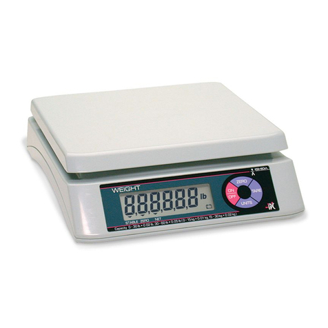
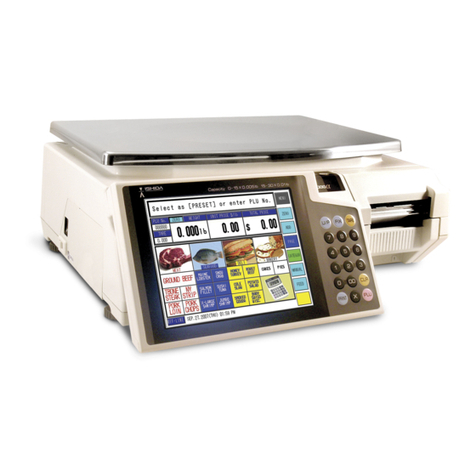
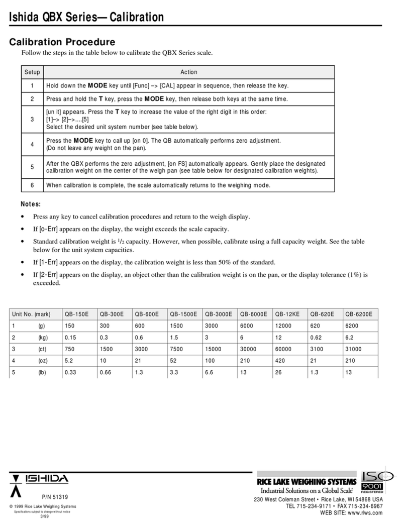
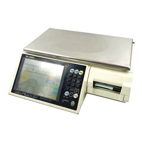
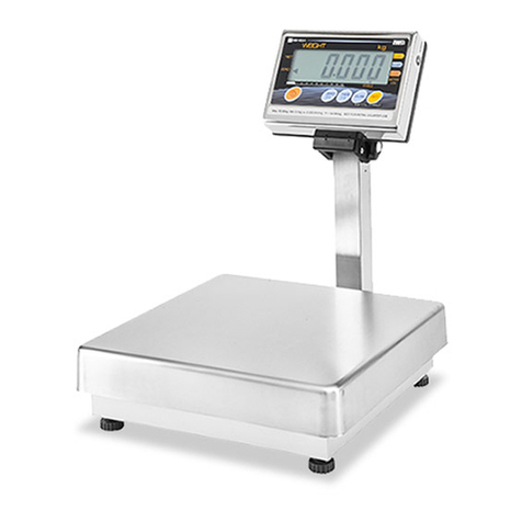
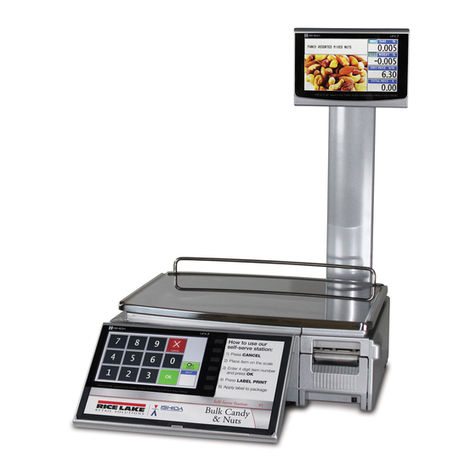
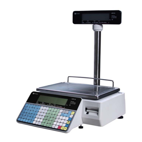
ISHIDA Uni-5 User manual

UNI-5
Service Manual
2nd Edition
IMPORTANT
Read this manual thoroughly, and do not perform
installation, operation, maintenance, or inspection
unless you fully understand all of the contents.
Keep this manual in a safe place where you can refer
to it easily while installing, operating, and carrying out
maintenance or inspections.
I
ssued
o
n 2-M
ar
-2
0
12

© ISHIDA Co., Ltd. 2012 All rights are reserved.
No part of this publication may be reproduced, stored in a retrieval system, or transmitted in any form or by any means
mechanical, electronic, photocopying, recording, or otherwise without prior written permission of ISHIDA.

NOTICES & PRECAUTIONS
UNI-5 Service Manual i
NOTICES
IMPORTANT NOTICE
Those who handle the machine must be aware of the hazards involved. These dangers may not be
obvious, so it is imperative to follow the instructions detailed in this manual when installing, operating,
inspecting, or servicing the machine. Therefore, we recommend that you thoroughly read and
understand this manual before installing, operating, inspecting, or servicing the machine.
ISHIDA is not liable for any damage, loss or injury that results from incorrect operation, insufficient
caution, unauthorized modifications to the machine, or failure to follow the instructions contained in
this manual.
LIMITATIONS OF LIABILITY
ISHIDA assumes no responsibility for special, indirect, or consequential damages, loss of profits or
commercial loss in any way connected with the machine, whether such claim is based on contract,
warranty, negligence, or strict liability.
ISHIDA assumes no responsibility for the user's programming of this machine, or any consequence
thereof.
In no event shall ISHIDA be responsible for warranty, repair, or other claims regarding the machine
unless ISHIDA’s analysis confirms that the machines were properly handled, stored, installed, and
maintained and not subject to contamination, abuse, misuse, or inappropriate modification or repair.
CHANGE IN SPECIFICATIONS
Machine specifications and accessories may be changed at any time due to improvements or other
reasons. Consult with your ISHIDA representative at any time to confirm the actual specifications of
the purchased machine.
ERRORS AND OMISSIONS
The information in this manual has been carefully checked and is believed to be accurate; however,
no responsibility is assumed for clerical, typographical or proofreading errors, or omissions.

NOTICES & PRECAUTIONS
ii UNI-5 Service Manual
PRECAUTIONS
PRECAUTION SYMBOLS
This machine is manufactured for use according to proper procedures by a qualified person and only
for the purposes described in this manual. The following conventions are used to indicate and classify
precautions depending on the level of danger, or seriousness of potential injury. Always heed the
information provided in this manual. Failure to heed precautions can result in personal injury or
property damage.
Indicates a potentially hazardous situation which, if not avoided, may result in
serious injury or death. Additionally, there may be significant property damage.
Indicates a potentially hazardous situation where, if not avoided, may result in
minor or moderate injury or in property damage.
Indicates reference information for operation.
Indicates the referred page for operation.

NOTICES & PRECAUTIONS
UNI-5 Service Manual iii
PRECAUTIONS FOR HANDLING
Do not allow water or any liquids to come into
contact with the machine.
Doing so may result in fire or cause the machine to
break down.
Do not drop or apply a strong shock to the
machine.
Doing so may cause the machine to break down.
Do not disassemble, modify, or attempt to repair
the machine.
Doing so may damage the original safety functions.
Do not hold the connector cover when carrying
the machine.
Dropping the machine may result in injury or cause
the machine to break down.
Do not hold the operation panel or weigh platter
when carrying the machine.
Doing so may cause the operation panel or the
platter to break down.
Do not hold the customer display the when
carrying the pole type machine.
Dropping the machine may result in injury or cause
the machine to break down.
Do not drop the cassette.
Dropping the cassette may result in injury or cause
the cassette to break down.

NOTICES & PRECAUTIONS
iv UNI-5 Service Manual
Handle with care when removing or inserting
the cassette.
Careless cassette handling may result in injury or
cause the cassette to break down.
Do not press the touch panel with an edged
thing.
Doing so may scratch the panel and cause the
machine to break down.
Do not dispose of batteries with normal
household waste. Please obey your local
regulations when disposing of used batteries.

NOTICES & PRECAUTIONS
UNI-5 Service Manual v
PRECAUTIONS WHEN USING CLEANING FLUIDS
Use a soft cloth and a neutral detergent to clean the machine.
Do not use thinner, benzene, etc. Doing so may damage the original safety functions.
For some parts, use cleaning fluid (isopropyl alcohol).
Do not use cleaning fluid near fire as the fluid is flammable.
Do not use cleaning fluid in a poorly ventilated area. Always provide adequate
ventilation when cleaning.
Take the following actions in the event of an accident:
If the fluid gets in your eye
Immediately wash your eye(s) with water for at least 15 minutes, and consult your doctor.
If you wear contact lenses, remove and wash them.
If the fluid comes into contact with your skin
Immediately rinse the area of contact with water, and then wash with soap.
If you notice any skin abnormalities at the area of contact, or if any pain persists, consult
your doctor.
If the fumes of the fluid are inhaled
Immediately move the victim to an area where fresh air is available, and have the victim
lie down and keep warm.
If breathing becomes difficult or stops, provide artificial respiration and seek medical
attention immediately.
If the fluid is swallowed
Do not try to induce vomiting.
Do not give the victim anything to drink, and do not rinse the mouth.
If vomiting occurs naturally, have the victim lean forward to reduce risk of aspiration.
Keep the victim warm and seek medical attention.

TABLE OF CONTENTS
vi UNI-5 Service Manual
TABLE OF CONTENTS
Chapter 1 BASIC INFORMATION
1.1 OUTER DIMENSIONS FOR EACH TYPE...................................................... 1-1
1.1.1 OUTER DIMENSIONS FOR BENCH TYPE................................................1-1
1.1.2 OUTER DIMENSIONS FOR POLE TYPE...................................................1-2
1.1.3 OUTER DIMENSIONS FOR SELF-SERVICE TYPE...................................1-3
1.1.4 OUTER DIMENSIONS FOR ELEVATED TYPE..........................................1-4
1.2 SPECIFICATIONS .......................................................................................... 1-5
1.3 INSTALLATION.............................................................................................. 1-6
1.3.1 POWER SUPPLY........................................................................................1-6
1.3.2 PRECAUTIONS FOR INSTALLATION........................................................1-7
Chapter 2 ASSEMBLY DRAWINGS
2.1 BENCH TYPE .................................................................................................2-1
2.2 POLE TYPE ....................................................................................................2-3
2.3 ELEVATED SINGLE PRINTER TYPE............................................................ 2-5
2.4 SELF-SERVICE TYPE.................................................................................... 2-7
2.5 ELEVATED DUAL PRINTER TYPE ...............................................................2-9
Chapter 3 BLOCK DIAGRAMS
3.1 BLOCK DIAGRAM (BENCH/POLE TYPE) ....................................................3-1
Chapter 4 ELECTRICAL SIGNALS
4.1 MAIN BOARD (PK-260).................................................................................. 4-1
4.2 KEY/LCD BOARD (PK-261)........................................................................... 4-6
4.3 LCD BOARD (PK-263) ...................................................................................4-8
4.4 WIRELESS LAN BOARD (PK-265)................................................................ 4-9
4.5 SELF-SERVICE MASTER BOARD (PK-266) ..............................................4-10
4.6 SELF-SERVICE MASTER BOARD (PK-267) ..............................................4-11
4.7 THERMAL BOARD (PK-268) ....................................................................... 4-12
4.8 THERMAL CONNECTOR BOARD (PK-268)............................................... 4-14
4.9 SCALE BOARD (PK-999)............................................................................. 4-16

TABLE OF CONTENTS
UNI-5 Service Manual vii
Chapter 5 MACHINE DISASSEMBLY
5.1 BENCH TYPE .................................................................................................5-1
5.1.1 UPPER CASE..............................................................................................5-1
5.1.2 WEIGH PLATTER HOLDER........................................................................5-2
5.1.3 MAIN BOARD..............................................................................................5-3
5.1.4 OPERATION PANEL...................................................................................5-4
5.1.5 CUSTOMER DISPLAY................................................................................5-6
5.1.6 LABEL SENSOR..........................................................................................5-8
5.1.7 PEEL SENSOR ...........................................................................................5-8
5.1.8 THERMAL HEAD UNIT ...............................................................................5-9
5.1.9 LOAD CELL & A/D BOARD.......................................................................5-10
5.1.10 POWER SUPPLY UNIT.............................................................................5-11
5.1.11 MOTOR UNIT............................................................................................5-12
5.1.12 WIRELESS LAN UNIT...............................................................................5-13
5.2 POLE TYPE .................................................................................................. 5-14
5.2.1 POLE UNIT................................................................................................5-14
5.2.2 CUSTOMER DISPLAY UNIT.....................................................................5-15
5.3 SELF-SERVICE TYPE.................................................................................. 5-16
5.3.1 SELF-SERVICE PANEL UNIT...................................................................5-16
5.3.2 PANEL CONTROL BOARD.......................................................................5-18
5.4 ELEVATED TYPE......................................................................................... 5-19
5.4.1 OPERATION PANEL UNIT ......................................................................5-19
5.4.2 CUSTOMER DISPLAY UNIT.....................................................................5-21
5.4.3 ELEVATED UNIT.......................................................................................5-22
Chapter 6 MECHANICAL ADJUSTMENT
6.1 FOUR CORNER LIMIT SPACE...................................................................... 6-1
6.2 GEAR ENGAGEMENT ................................................................................... 6-2
6.3 PRINT POSITION............................................................................................ 6-3
6.4 THERMAL HEAD POSITION.......................................................................... 6-4

Chapter 1 BASIC INFORMATION
UNI-5 Service Manual 1-1
BASIC INFORMATION
1.1 OUTER DIMENSIONS FOR EACH TYPE
1.1.1 OUTER DIMENSIONS FOR BENCH TYPE
1

Chapter 1 BASIC INFORMATION
1-2 UNI-5 Service Manual
1.1.2 OUTER DIMENSIONS FOR POLE TYPE

Chapter 1 BASIC INFORMATION
UNI-5 Service Manual 1-3
1.1.4 OUTER DIMENSIONS FOR ELEVATED TYPE

Chapter 1 BASIC INFORMATION
1-4 UNI-5 Service Manual
1.2 SPECIFICATIONS
Items Descriptions
Use conditions Temperature: -5 to 35°C
Humidity: 30 to 85%, Non condensing.
Power supply: AC100 – 240V, 50 / 60Hz
Power consumption 1.0A/0.5A
Weighing capacity
Scale interval 15 kg: 0 to 6/0.002 kg, 6 to 15/0.005 kg
30 lb: 0 to 15/0.005 lb, 15 to 30/0.01 lb
Weighting accuracy 1/3000
Operator/Customer display 7.0 inch color liquid crystal with back light, 480 X 234dots
Printing method Direct thermal method
Thermal head 2 inches (448dots) and 8 dots/mm
Printing speed 100mm/second, 120mm/second
Note: The printing speed may vary according to label conditions.
Printing effective size 56mm
Label size Label width: 30mm to 60mm
Label length: 20mm to 150mm
Input/Output LAN 1 channel
USB 1 channel
CF 1 channel
Drawer 2 channels
Program store medium Flash ROM (32M bytes)

Chapter 1 BASIC INFORMATION
UNI-5 Service Manual 1-5
1.3 INSTALLATION
1.3.1 POWER SUPPLY
It is strongly advised that the following safety measures must be observed to ensure the safe
operation of the machine:
Read precaution instructions described in this manual before connecting the power plug
into the outlet.
Always use a power supply with rated voltage. Never connect the machine power input with
an AC power supply exceeding the rated voltage. To avoid any potential electrical shock,
ensure that the protective ground wire is connected to the main grounding provision.
Using the machine outside of the rated voltage may result in machine failure or danger such as
electric shock.
Prepare a dedicated power source.
A power supply that generates voltage variation may cause a malfunction.
Do not stand on the power cable, and do not place anything heavy on the cable.
Doing so may damage the cable, resulting in accident or trouble.
Disconnect power supply before servicing.
To ensure your personal safety, disconnect the power supply before servicing.
Take precaution against residual electrical charge hazard.
Capacitors inside the machine may still hold an electrical charge even after power is disconnected.
Do not remove covers or enclosures.
To avoid personal injury and shock, do not open or remove any covers or enclosures of the machine
unless specified in the manual.
Do not perform unspecified maintenance.
For your personal safety, do not perform any maintenance procedures which are not specified in the
manual.

Chapter 1 BASIC INFORMATION
1-6 UNI-5 Service Manual
1.3.2 PRECAUTIONS FOR INSTALLATION
Do not install the machine in the following types of places:
Places subject to high
temperatures or high humidity
Places exposed to direct
sunlight
Places where water or other
liquids are easily spilled on the
machine
Places subject to excessive
vibration or unstable
foundations
Places exposed to direct cold
air from air conditioners or
refrigerators
Places where the floor or
foundation is unstable
Places subject to a lot of
dust or dirt
Places with large voltage
fluctuations

Chapter 2 ASSEMBLY DRAWINGS
UNI-5 Service Manual 2-1
ASSEMBLY DRAWINGS
2.1 BENCH TYPE
2

Chapter 2 ASSEMBLY DRAWINGS
2-2 UNI-5 Service Manual
Parts List (Bench Type)
NO. PART NAME Q'TY NO. PART NAME Q'TY
1 GUIDE PLATE 1 45 BRACKET CONNECTOR ASSY 1
2 PLATTER ASSY 1 46 PWB PK-265A 1
3 CASE MAIN UPPER 1 47 HARNESS C4 SWITCH ASSY 1
4 COVER PRINTER UPPER 1 48 COVER SWITCH 1
5 COVER HINGE UPPER 1 49 STICKER 'SEAL' 2
6 COVER HINGE LOWER 1 50 ANTENNA 1
7 PLATTER SUPPORT 1 51 COVER BRACKET CONNECTOR 1
8 BLOCK B HINGE PLATTER 2 52 BASE 1
9 RUBBER PLATER SUPPOR 5 53 STICKER VOID 2
13 CASE A/D BOARD 1 54 PLATE B RS232C 1
14 PWB P-999B 1 56 BLOCK B HINGE SIDE COVER 1
15 SCREW 'SEAL' HEXA 1 57 FOOT ADJUST 4
16 SCREW 'SEAL' HEXA 1 58 COVER SIDE 1
17 PWB PK-270C 1 59 COVER HARNESS 1
18 HARNESS S2 5V POWER 1 60 POWER SUPPLY 1
19 HARNESS S2 REAR LCD 1 61 BRACKET POWER 1
20 HARNESS S2 FRONT LCD 1 62 CASE REAR COVER 1
21 FERRITE CORE 3 63 PWB PK-263A 1
22 FERRITE CORE 2 64 LCD 1
23 SHEET INSULATION 1 65 CASE REAR PANEL 1
24 ACCESSORY PWB GUIDE SPACE 2 66 CAP 4
25 HARNESS S2 24V DC POWER 1 67 HARNESS C2 POWER ASSY 1
26 SHEET DOUBLE TAPE 1 68 SHEET KEY BOARD-PLU 1
27 HARNESS C2 A/D 1 70 HARNESS S2 LAN 1
28 BRACKET LEVEL 1 71 STICKER LOCATION OUTPUT 1
29 LEVEL UNIT 1 72 GASKET 20mm 1
30 FRAME LEVEL 1 73 STICKER IMPORTANT 1
31 LEVEL LENS 1 74 GASKET 115mm 1
32 BRACKET HINGE 1 75 FERRITE CORE 1
33 HINGE L 1 76 LOADCELL ASSEMBLY 1
34 HINGE R 1 77 SHEET INSULATION POWER SUPPLY 1
35 EARTH CLAMP 4 78 POWER CORD 1
36 CASE REAR CONTROLL 1 79 STICKER 'M' 1
37 PWB PK-261A 1 83 HARNESS C2 HEAD 1
38 ACCESSORY PCB SUPPORT 4 84 HARNESS C3 SENSOR 1
39 BRACKET LCD 2 85 COVER PRINTER 1
40 LCD TOUCH 1 86 MAGNETIC 1
41 CASE FRONT CONTROLL 1 87 STICKER LABEL SETTING 1
42 KEY BOARD MEMBRANE 1 88 BRACKET LABEL PEEL 1
43 SHEET KEY BOARD-SETTING 1 89 PLATE A COVER 1
44 COVER KEY BOARD 1 90 FRONT LCD ASSY 1

Chapter 2 ASSEMBLY DRAWINGS
UNI-5 Service Manual 2-3
2.2 POLE TYPE

Chapter 2 ASSEMBLY DRAWINGS
2-4 UNI-5 Service Manual
Parts List (Pole Type)
NO. PART NAME Q'TY NO. PART NAME Q'TY
1 GUIDE PLATTER 1 49 STICKER SEAL 3
2 PLATTER ASSY 1 50 ANTENNA 1
3 CASE MAIN UPPER 1 51 COVER BRACKET CONNECTOR 1
4 COVER PRINTER UPPER 1 52 BASE 1
5 COVER HINGE UPPER 1 53 STICKER VOID 2
6 COVER HINGE LOWER 1 54 PLATE B RS232C 1
7 PLATTER SUPPORT 1 56 BLOCK B HINGE SIDE COVER 1
8 BLOCK B HINGE PLATTER 2 57 FOOT ADJUST 4
9 RUBBER PLATTER SUPPORT 5 58 COVER SIDE 1
13 CASE A/D BOARD 1 59 COVER HARNESS 1
14 PWB P-999B 1 60 POWER SUPPLY 1
15 SHEET KEY BOARD-PLU 1 61 BRACKET POWER 1
16 SCREW SEAL HEXA 1 62 CASE REAR POLE 1
17 PWB PK-270C 1 63 PLATE B BRACKET POLE 1
18 HARNESS S2 5V POWER 1 64 BRACKET POLE STAND 1
19 HARNESS S2 REAR LCD
(
POLE
)
1 65 POLE STAND 1
20 HARNESS S2 FRONT LCD 1 66 CASE LINK POLE 1
21 GASKET 115mm 1 67 CAP 6
22 FERRITE CORE 2 68 CASE REAR POLE DISPLAY 1
23 FERRITE CORE 2 69 PWB PK-263A 1
24 ACCESSORY PWB GUIDE SPACER 4 70 LCD 1
25 HARNESS S2 24V DC POWER 1 71 CASE FRONT POLE DISPLAY 1
26 SHEET INSULATION 1 72 SHEET DISPLAY PANEL 1
27 HARNESS C2 A/D 1 73 SCREW SEAL HEXA 1
28 BRACKET LEVEL 1 74 HARNESS C2 POWER ASSY 1
29 LEVEL UNIT 1 75 STICKER 'M' 1
30 FRAME LEVEL 1 77 STICKER LOCATION OUTPUT 1
31 LEVEL LENS 1 78 GASKET 20mm 1
32 BRACKET HINGE 1 79 SHEET DOUBLE TAPE 1
33 HINGE L 1 80 COVER CASSETTE 1
34 HINGE R 1 81 FERRITE CORE 1
35 EARTH CLAMP 4 82 LOADCELL ASSEMBLY 1
36 CASE REAR CONTROLL 1 83 SHEET INSULATION POWER SUPPLY 1
37 PWB PK-261A 1 84 POWER CORD 1
38 ACCESSORY PCB SUPPORT 4 85 NAME PLATE SPEC 2
39 BRACKET LCD 2 86 NAME PLATE SERIAL 1
40 LCD TOUCH 1 87 FERRITE CORE 1
41 CASE FRONT CONTROLL 1 88 HARNESS C2 HEAD 1
42 KEY BOARD MEMBRANE 1 89 HARNESS C3 SENSOR 1
43 SHEET KEY BOARD-SETTING 1 90 MAGENT 1
44 COVER KEY BOARD 1 91 STICKER LABEL SETTING 1
45 BRACKET CONNECTOR ASSY 1 92 STICKER IMPORTANT 1
46 PWB PK-265A 1 93 BRACKET LABEL PEEL 1
47 HARNESS C4 SWITCH ASSY 1 94 PLATE A COVER 1
48 COVER SWITCH 1 95 FRONT LCD ASSY 1

Chapter 2 ASSEMBLY DRAWINGS
UNI-5 Service Manual 2-5
2.3 ELEVATED SINGLE PRINTER TYPE
Parts List (Elevated Single Printer type)
NO. PART NAME Q'TY NO. PART NAME Q'TY
1 SHEET DISPLAY PANEL 1 11 SHEET KEY BOARD-PLU 1
2
CASE FRONT POLE DISPLAY
1
12
SHEET KEY
BOARD
-
SETTING
1
3 LCD 1 13 KEY BOARD MEMBRANE 1
4 BRACKET LCD 2 14 CASE FRONT CONTROLL 1
5 ACCESSORY PCB SUPPORT 4 15 LCD TOUCH 1
6 PWB PK-263A 1 16 SHEET DOUBLE TAPE 1
7 CASE REAR POLE DISPLAY 1 17 GASKET 115mm 1
8
HINGE R
2
18
COLLAR SPACER
4
9 COVER JOINT REAR 1 19 PWB PK-261A 1
10 COVER KEY BOARD 1 20 CASE PRINTER 1
Other manuals for Uni-5
1
Table of contents
Other ISHIDA Scale manuals

ISHIDA
ISHIDA UNI-7 User manual

ISHIDA
ISHIDA IPC 3kg User manual

ISHIDA
ISHIDA AC-4000 Series User manual

ISHIDA
ISHIDA INS-100 User manual

ISHIDA
ISHIDA BC-3000 User manual

ISHIDA
ISHIDA INS-100 User manual

ISHIDA
ISHIDA IPC-WP User manual

ISHIDA
ISHIDA AC-4000 Series User manual

ISHIDA
ISHIDA Astra Instruction Manual

ISHIDA
ISHIDA INS-100 9k User manual

ISHIDA
ISHIDA IWX-150/30 User manual

ISHIDA
ISHIDA BC-300 User manual

ISHIDA
ISHIDA AC-4000H User manual

ISHIDA
ISHIDA IWB Series User manual

ISHIDA
ISHIDA Uni-3 User manual

ISHIDA
ISHIDA BC-4000 User manual

ISHIDA
ISHIDA IP-EMZ User manual

ISHIDA
ISHIDA Uni-5 User manual

ISHIDA
ISHIDA UNI-7 User manual

ISHIDA
ISHIDA UNI-7 User manual