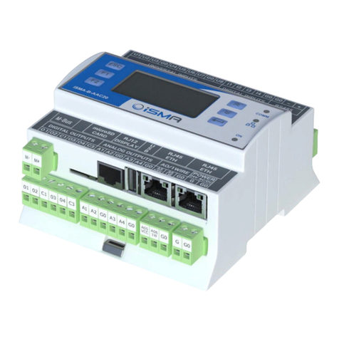
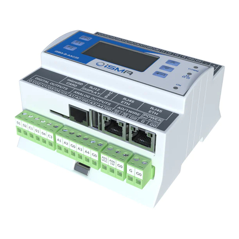
iSMA B-AAC20D User manual

iSMA-B-AAC20D
User Manual
DALI Network
Global Control 5 Sp. z o.o.
Warsaw, Poland
www.gc5.pl

iSMA-B-AAC20 DALI manual
Page 2 / 19
Table of Contents
1Sedona DALI........................................................................................................................... 3
1.1 Revision history.............................................................................................................. 3
2Installing iSMA DALI kit ........................................................................................................ 4
2.1 Install kit on iSMA-B-AAC20 device .......................................................................... 5
2.2 Remove DALI kit from iSMA-B-AAC20 device.......................................................... 6
3DALI Network kit.................................................................................................................... 7
3.1 DALI license and limitation .......................................................................................... 7
3.2 DALI Network component............................................................................................ 8
DALI Network actions- Device Discover and New Initialization.................... 9
4DALI Device ..........................................................................................................................10
4.1 DALI Scenes and Groups ...........................................................................................12
5DALI light control components.........................................................................................13
5.1 DALI Command............................................................................................................13
5.2 DALI On Off ...................................................................................................................14
5.3 DALI On Off Dimming 1 Switch.................................................................................14
5.4 DALI On Off Dimming 2 Switch.................................................................................15
5.5 DALI On Off Preset Value ...........................................................................................17
5.6 DALI On Off Recall Scene...........................................................................................18
5.7 DALI Scene Setter........................................................................................................19
iSMA-B-AAC20 DALI manual
Page 3 / 19
1Sedona DALI
What DALI is?
DALI is an abbreviation for Digital Addressable Lighting Interface.
DALI is a protocol, in which DALI devices communicate with each other.
In other words, Dali is the language in which DALI devices talk to each other.
DALI (digital addressable lighting interface) is a two-way communication system that
brings digital technology to lighting. An international standard for communication,
DALI defines the commands that ballasts need to recognize in order to be considered
uters equipped with appropriate
software, or building management systems (BMS).
Warning! Before programming Sedona DALI kit please check if you are using the latest
kit version. The latest kits are available on GC5 support web site www.support.gc5.pl
1.1 Revision history
1.0
28.08.2015
First edition
1.1
03.06.2016
Enable/Disable DALI bus power supply
1.2
05.02.2018
Added lights control components
1.3
10.04.2019
Added DALI Scene Setter

iSMA-B-AAC20 DALI manual
Page 4 / 19
2Installing iSMA DALI kit
To install Sedona DALI kit, import the kit to the WorkPlace software (possibly as part
of the package of various kits in a zip file). To do this, use an application from the
Tools menu -> Sedona Installer.
After successful import of the files, upload the files to your device using the Kit
Manager Application from the Sedona Tools package.
Warning! Before programming Sedona DALI Network please check if you are using the
latest kit version. The latest kit is available on GC5 support web site
www.support.gc5.pl

iSMA-B-AAC20 DALI manual
Page 5 / 19
2.1 Install kit on iSMA-B-AAC20 device

iSMA-B-AAC20 DALI manual
Page 6 / 19
2.2 Remove DALI kit from iSMA-B-AAC20 device

iSMA-B-AAC20 DALI manual
Page 7 / 19
3DALI Network kit
DALI Network kit consists of 11 types of components:
•
•
•
•
•
•
•
•
•
•
•
3.1 DALI license and limitation

iSMA-B-AAC20 DALI manual
Page 8 / 19
3.2 DALI Network component
DALI network component is a main component which is response for servicing DALI
physical interface. Component must be placed under Drivers folder.
•Status Network status, available states:
-OK Network is working properly,
-Disabled
•Fault Cause Fault cause description,
•Power Supply - Switches to on/off DALI network power supply.
Note: As part of the DALI Network component, configuration actions performed by the
integrator (Discover, or ReadDevice and WriteDevice of the DALI Device component)
have a common context. By doing this action during the implementation of another
action, the previous action will be interrupted and the new action will be started. The
communication acquisition status is not show in any way (status slot or console),

iSMA-B-AAC20 DALI manual
Page 9 / 19
therefore, depending on the DALI communication speed set, the integrator must allow
a certain time to execute the command and start the next command after that time.
DALI Network actions- Device Discover and New Initialization

iSMA-B-AAC20 DALI manual
Page 10 / 19
4DALI Device
•
•
•
•
•
•
•
•
•
•
•
•

iSMA-B-AAC20 DALI manual
Page 11 / 19
•
•
•
•
•
•
•

iSMA-B-AAC20 DALI manual
Page 12 / 19
4.1 DALI Scenes and Groups

iSMA-B-AAC20 DALI manual
Page 13 / 19
5DALI light control components
5.1 DALI Command
Defining the function, further parameters can be set to select the destination address
for which the function is intended (group or individual address) and the type of Sedona
DALI command to be performed.
Sedona DALI Protocol allows addressing of individual 'control gear' (ballasts, relays,
dimming circuits, etc.) without needing to refer to a parent device.
Sedona DALI Command is used for triggering Sedona DALI commands. Individual in
will cause the associated Sedona DALI command to be sent to the control gear.
DALI Device component has the following actions:
•
Sedona DALI command has the following slots:
•
•
•
•
•
•
•

iSMA-B-AAC20 DALI manual
Page 14 / 19
5.2 DALI On Off
This component has built-in DALI command which will be send to DALI device/devices
on slots On and Off rising edge
The component has the following actions:
•
•
The component has the following slots:
•
•
•
•
•
•
5.3 DALI On Off Dimming 1 Switch
This component has the built-in DALI command which allows to switch On and Off or
to change DALI device/devices lighting level. This component was designed to work
with single switch (one button connect to one digital input). The switch is working in
two modes - short and long press. The short press (when Switch slot is in true mode
for the time below parameter defined in Long Press slot), recall toggle function so each
short press sends On / Off command to DALI device/devices. The long press is to
increase or decrease lighting level. Each press toggle between increase or decrease
function. Current lighting level is stored in the device in scene number defined in slot
Scene No For Last Level (in default scene no 15). The short press On command will
recall lighting lever stored in this scene. The component knows how to perform the next

iSMA-B-AAC20 DALI manual
Page 15 / 19
action based on the actions previously performed on it, therefore it is not suitable for
connection with other components affecting the same ballast (whether by Address
Type Single or Group or All). Each action performed on a ballast by another component
will cause the action to un-synchronize in DALI On Off Dimming 1 Switch.
The component has the following actions:
•
The component has the following slots:
•
•
•
•
•
•
•
5.4 DALI On Off Dimming 2 Switch
This component has the built-in DALI command which allows to switch On and Off or
to change DALI device/devices lighting level. This component was designed to work
with double switch (one button for switch on and dimm up, second for switch off and
dimm down). The switch is working in two modes short and long press. The short press

iSMA-B-AAC20 DALI manual
Page 16 / 19
(when Switch slot is in true mode for the time below parameter defined in Long Press
slot), recall On / Off command to DALI device/devices. The long press is for increasing
or decreasing the lighting level. Current lighting level is stored in the device in scene
number defined in slot Scene No For Last Level (in default scene no 15). The short press
On command will recall lighting lever stored in this scene. The component does not
check the actions it has performed recently, it only performs actions determined on the
basis of triggering the corresponding inputs, therefore it is suitable for connection with
other components affecting the same ballast (whether by Address Type Single or Group
or All).
The component has the following actions:
•
•
The component has the following slots:
•
•
•
•
•

iSMA-B-AAC20 DALI manual
Page 17 / 19
•
•
•
5.5 DALI On Off Preset Value
This component has the built-in DALI command which sends direct lighting level to
DALI device/devices. The component has defined two sending slots so different
values for On and Off trigger can be defined.
The component has the following actions:
•
•
The component has the following slots:
•
•
•
•
•

iSMA-B-AAC20 DALI manual
Page 18 / 19
•
•
•
5.6 DALI On Off Recall Scene
This component has the built-in DALI command which sends recall scene command
to DALI device/devices. The component has defined two scenes number and trigger
slots so define different scenes for On and Off trigger can be defined.
The component has the following actions:
•
•
The component has the following slots:
•
•
•
•

iSMA-B-AAC20 DALI manual
Page 19 / 19
•
•
•
•
5.7 DALI Scene Setter
This component allows for building an application, in which the user is able to change
the value of the scene in the ballast independently without the need to use the
configuration software. In the component, the Scene Number value defines the scene
which value is to be changed to the current level of the luminaire (actual level).
The component has the following actions:
•
The component has the following slots:
•
•
•
•
•
•
Table of contents
Other iSMA Controllers manuals

iSMA
iSMA iSMA-B-MAC36NL User manual

iSMA
iSMA iSMA-B-AAC20 User manual

iSMA
iSMA iSMA-B-MAC36NL Installation manual

iSMA
iSMA iSMA-B-AAC20 User manual

iSMA
iSMA MVE2 Series User manual

iSMA
iSMA B-FCU User manual

iSMA
iSMA iSMA-B-MAC36NL User manual

iSMA
iSMA iSMA-B-FCU Series User manual

iSMA
iSMA iSMA-B-MAC36NL User manual

iSMA
iSMA SMA-B-LP User manual
Popular Controllers manuals by other brands

SPX
SPX MARLEY LLC+ui user manual

Maguire Products
Maguire Products Weigh Scale Blender WSB Operation & maintenance manual

CHIAROSCURO
CHIAROSCURO SLIDE.80 Use and installation manual

Becker
Becker CentralControl CC31 Commissioning instructions

SunMaxx Solar
SunMaxx Solar SmartMaxx-Pro-XL6D installation guide

LEGRAND
LEGRAND 488 43 quick start guide