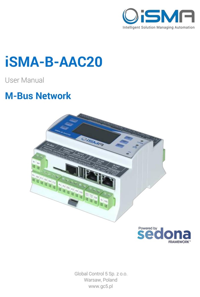
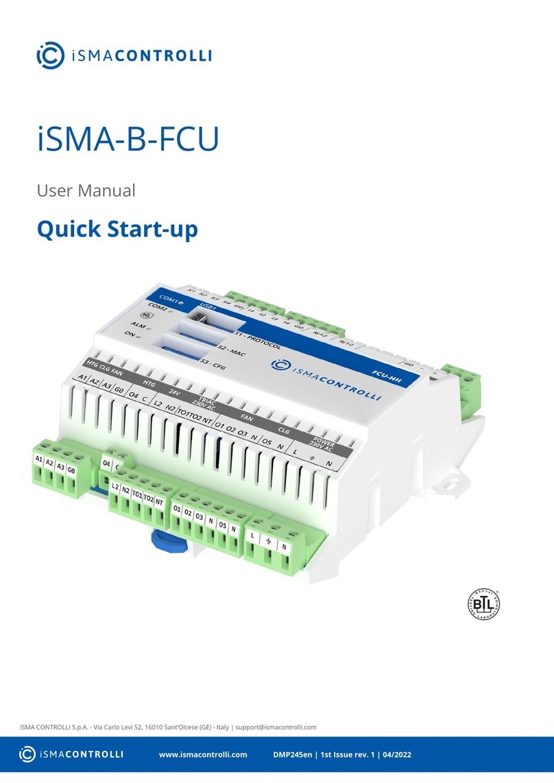
iSMA B-AAC20 User manual

iSMA-B-AAC20
User Manual
M-Bus Network
Global Control 5 S.A.
Warsaw, Poland
www.globalcontrol5.com

User manual iSMA-B-AAC20/M-Bus Network
Table of Contents
1 Introduction 3
1.1 Revision History 3
2 M-Bus Kit 3
2.1 Installation of the iSMA M-Bus Kit 3
3 About M-Bus 4
3.1 M-Bus Topology and Cable 4
3.2 M-Bus Addressing 5
4 M-Bus Kit Components 5
5 M-Bus Local Network Component 6
6 M-Bus Local Device 7
6.1 M-Bus Local Device Points 9
7 M-Bus IP Network 9
8 M-Bus IP Device 11
8.1 M-Bus IP Device points 13

User manual iSMA-B-AAC20/M-Bus Network
Version 1.2 www.globalcontrol5.com Page 3/ 13
1 Introduction
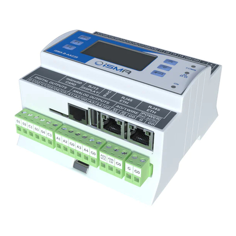
This manual contains information about an M-Bus protocol in the iSMA-B-AAC20 controllers.
M-Bus devices can be connected directly only to the iSMA-B-AAC20-M hardware version
with the M-Bus interface (max. 20 devices) and with firmware version 5.1 and above. The M-
Bus devices can also be connected to all iSMA-B-AAC20 controllers with firmware 5.1 and
above using M-Bus-IP gateway.
1.1 Revision History
Rev
Date
Description
1.0
22.11.2016
First edition
1.1
20.04.2017
Added action “Reset Stat” in the network components
1.2
27.01.2020
Replaced environment of programming from Workplace to
iSMA Tool
Table 1 Revision history
2 M-Bus Kit
To serve the M-Bus protocol (connected either to the Local interface or by the IP gateway)
the iSMA-B-AAC20 controller uses the iSMA_MBus kit.
2.1 Installation of the iSMA M-Bus Kit
To install the M-Bus kit, import the kit to the iSMA Tool software (possibly as part of the
package of the various kits in a zip file). To do this, use an application from the Sedona ->
Import Sedona Files.
After a successful import of the files, upload them to your device using the Kit Manager
Application from the Sedona Tools package.
WARNING! Before programming the M-Bus Network, please check if the latest kit version is
used. The latest kits are available at GC5 support web site: www.support.gc5.pl

User manual iSMA-B-AAC20/M-Bus Network
Version 1.2 www.globalcontrol5.com Page 4/ 13
Figure 1 Sedona Installer
3 About M-Bus
The M-Bus (Meter Bus) was developed to fill the need for a system for the networking and
remote reading of utility meters, for example, to measure the consumption of gas or water in
the house. This bus fulfils the special requirements of remotely powered or battery-driven
systems, including consumer utility meters. When interrogated, the meters deliver the data
they have collected to a common master, for example, a DDC controller or a hand-held
computer, connected at periodic intervals to read all utility meters of a building.
3.1 M-Bus Topology and Cable
The M-Bus is a hierarchical system, with communication controlled by a master (for
example the iSMA-B-AAC20-M). The M-Bus consists of the master, a number of slaves (end-
equipment meters), and a two-wire connecting cable. The slaves are connected in parallel to
the transmission medium - the connecting cable.

User manual iSMA-B-AAC20/M-Bus Network
Version 1.2 www.globalcontrol5.com Page 5/ 13
Figure 2 M-Bus connection topology
A two-wire cable (jYStY N*2*0.8 mm) is used as the transmission medium for the M-Bus.
The maximum distance between the slave and the repeater is 350 m; this length
corresponds to a cable resistance of up to 29 Ω. This distance applies for the standard
configuration having a baud rate between 300 and 9600 baud rate, and a maximum of 250
slaves. The maximum distance can be increased by limiting the baud rate and using fewer
slaves, but the bus voltage in the Space state must at no point in a segment fall below 12 V,
because of the remote powering of the slaves. In the standard configuration, the total cable
length should not exceed 1000 m, in order to meet the requirement of a maximum cable
capacitance of 180 nF.
3.2 M-Bus Addressing
The M-Bus devices are using two types of addressing:
•Primary: This address is assigned by the user in a commissioning process (all new M-
Bus devices have this address, set by the factory to 0); this type of address has a
limited range from 0 to 250;
•Secondary: This address has a wider range than primary and by default contains a
device serial number. All out of box devices connected to the bus have unique
secondary addresses.
4 M-Bus Kit Components
The M-Bus kit contains two types of device components based on communication interface:
•Local Device: for devices connected directly to the iSMA-B-AAC20-M (this connection
requires a special hardware version equipment with the M-Bus interface). This type of
communication is using two components:
•MbusLocalNetwork: The main component responsible for handling local interface,
•MbusLocalDevice: The component responsible for handling devices connected to
the local interface;

User manual iSMA-B-AAC20/M-Bus Network
Version 1.2 www.globalcontrol5.com Page 6/ 13
•IP Device: for devices connected by the M-Bus-IP gateway (for all types of hardware
versions):
•MbusIPNetwork: The main component responsible for the connection to the M-
Bus-IP gateway,
•MbsuIPDevice: The component responsible for handling devices connected to the
M-Bus-IP gateway.
The iSMA_Mbus kit does not have devices points components available for the user’s use.
The devices’points are added automatically during the points discovery process.
This kit contains the MbusFolder component to segregate the devices and points.
5 M-Bus Local Network Component
This component is responsible for servicing the M-Bus devices connected directly to the
iSMA-B-AAC20-M M-Bus interface. The max. number of devices connected to the iSMA-B-
AAC20 is 20, and it is a hardware limitation (a built-in M-Bus power supply).
Figure 3 M-Bus Local Network property sheet view
This component has the following actions:
•Search Primary Address: Discovers devices connected to the M-Bus Local interface by
the Primary Address.
The user can also enter the searching range in action pop-up window by doing a simple
calculation: Range Number = Start Address * 256 + End Address, for example, to search
range from 10 to 20 the user must enter 2580 (10*256 + 20=2580).
WARNING! All new devices have the default Primary Address set to 0, it is recommended
to search by the Secondary Address for new devices.

User manual iSMA-B-AAC20/M-Bus Network
Version 1.2 www.globalcontrol5.com Page 7/ 13
•Search Secondary Address: Discovers devices connected to the M-Bus Local interface
by the Secondary Address. This address contains the device’s serial number assigned by
factory. This action is recommended for the first bus commissioning;
•Read Network: Forces devices data read;
•Reset Stats: Resets network statistics and starts calculating from 0.
The component has the following slots:
•Status: Component’s current status;
•Fault Cause: Fault cause description;
•Enabled: Enables/Disables the M-Bus Local Network;
•Last Discovery Time: Last success discovery action time;
•Retry Count: Max. number of error messages (CRC error, lost messages) before device
down;
•Initialization Delay: Delay time after initialization message;
•Response Timeout: Max. device response time from the device request;
•Inter Message Delay: Time between messages sent to the device,;
•Fast Rate: Time between device read in „Fast” mode poll frequency;
•Normal Rate: Time between device read in „Normal” mode poll frequency;
•Slow Rate: Time between device read in „Slow” mode poll frequency;
•Read Trigger: Remote force device data read trigger;
•Average Poll Time: Average time for sending/receiving one message;
•Busy Time: Percentage of the M-bus network usage;
•Total Polls: Total number of messages;
•Fast Polls: Number of messages sent in „Fast” mode;
•Normal Polls: Number of messages sent in „Normal” mode;
•Slow Polls: Number of messages sent in „Slow” mode;
•Timeouts:Number of lost messages, the difference between sent and received
messages;
•Errors: Number of error messages (for example, with wrong CRC);
•Baud Rate: Default network M-Bus Local port baud rate, available options:
300, 600, 1200, 2400, 4800, 9600, 19200, 38400.
Parameters like: Retry Count, Initialization Delay, Response Timeout, Inter Message Delay
and Baud Rate are used in device discover action. If it is required, these parameters can have
different settings in the devices than the network (the devices connected to the bus can
have different communications parameters).
6 M-Bus Local Device
The M-Bus Local Device is a component for servicing the M-Bus devices connected to the
User manual iSMA-B-AAC20/M-Bus Network
Version 1.2 www.globalcontrol5.com Page 8/ 13
iSMA-B-AAC20-M M-Bus interface (this connection requires a special hardware version
equipment with the M-Bus interface).
There are two ways to add the M-Bus Local Device to the application:
•Manual: By drag and drop from a Sedona Palette to the network component. In this case,
the user must know the M-Bus device address (Primary or Secondary);
•Automatic: By using a discover action in the network component. For the first
commissioning, it is recommended to search by the Secondary Address and then assign
the Primary Address. All new devices have factory default Primary Address set to 0.
WARNING! ALL discovered devices are placed in the DiscoveredDevices folder. In this folder,
devices are read only, for normal use they must be moved from this folder and placed
directly to another MbusFolder under the MbusLocalNetwork component.
Figure 4 - M-Bus Local Device property sheet view
This component has the following actions:
•Read: Forces the device data read;
•Set Primary Address: Sets the Primary Address to the device (range from 0 to 250); this
action automatically sets the Address Mode to the Primary Address;
•Discover Points: This action decodes the device message and creates points according
to the device specification.
The component has the following slots:
•Status: Component’s current status;

User manual iSMA-B-AAC20/M-Bus Network
Version 1.2 www.globalcontrol5.com Page 9/ 13
•Fault Cause: Fault cause description;
•Enabled: Enables/Disables the M-Bus Local Device;
•Last Read Success: Last proper success device read time;
•Poll Frequency: Device read frequency (times defined in the network component),;
•Address Mode: Define device communication type address (Primary or Secondary);
•Primary Address: Device Primary Address;
•Secondary: Device Secondary Address;
•Retry Count: Max. number of error messages (CRC error, lost messages) before the
device down;
•Initialization Delay: Delay time after initialization message;
•Response Timeout: Max. device response time from the device request;
•Inter Message Delay: Time between messages sent to the device,;
•Manufacturer: Manufacturer description read from device (read only);
•Device Type Id: The M-Bus Device Type ID read from device (read only);
•Read Trigger: Remote force device data read trigger;
•Baud rate: Device read baud rate, available options:
300, 600, 1200, 2400, 4800, 9600, 19200, 38400.
6.1 M-Bus Local Device Points
The iSMA_Mbus kit does not have device points components available in the Sedona Palette
for the user’s use. The devices points are added automatically during the points discovery
process. In the discovery process, the response message is decoded, and based on this
information the iSMA-B-AAC20 creates corresponding points components. The iSMA_Mbus
kit uses two types of components:
•Numeric: for numeric values;
•String: for values other than numeric like description, time, etc.
Note: The M-Bus device always responses by a full message, so the number of components
has no influence on the network traffic. To maintain the order the user can delete unused
components.
7 M-Bus IP Network
This component is responsible for servicing the M-Bus devices connected to the iSMA-B-
AAC20 controller by the IP network and IP-M-Bus gateway. The max. number of devices
connected to the bus is limited by a gateway specification.

User manual iSMA-B-AAC20/M-Bus Network
Version 1.2 www.globalcontrol5.com Page 10 / 13
Figure 5 M-Bus IP Network property sheet view
This component has the following actions:
Search Primary Address: Discovers devices connected to the M-Bus Local interface by the
Primary Address.
The user can also enter the searching range in action pop-up window by doing a simple
calculation: Range Number = Start Address * 256 + End Address, for example, to search a
range from 10 to 20 the user must enter 2580 (10*256 + 20=2580).
WARNING! All new devices have the default Primary Address set to 0, it is recommended to
search by the Secondary Address for new devices.
•Search Secondary Address: Discover devices connected to the M-Bus Local interface by
Secondary Address. This address contains part of the device serial number and is
assigned in the factory. This action is recommended for the first bus commissioning.
•Read Network: Force devices data read,
•Reset Stats: Reset network statistic and start calculating from 0.
The component has the following slots:
•Status: Component’s current status;
•Fault Cause: Fault cause description;
•Enabled: Enables/Disables the M-Bus Local Network;
•Last Discovery Time: Last success discovery action time;
•Retry Count: Max. number of error messages (CRC error, lost messages) before device
down;

User manual iSMA-B-AAC20/M-Bus Network
Version 1.2 www.globalcontrol5.com Page 11 / 13
•Initialization Delay: Delay time after initialization message;
•Response Timeout: Max. device response time from the device request;
•Inter Message Delay:Time between messages sent to the device,;
•Fast Rate: Time between device read in „Fast” mode poll frequency;
•Normal Rate: Time between device read in „Normal” mode poll frequency;
•Slow Rate: Time between device read in „Slow” mode poll frequency;
•Read Trigger: Remote force device data read trigger;
•Average Poll Time: Average time for sending/receiving one message;
•Busy Time: Percentage of M-bus network usage;
•Total Polls: Total number of messages;
•Fast Polls: Number of messages sent in „Fast” mode;
•Normal Polls: Number of messages sent in „Normal” mode;
•Slow Polls: Number of messages sent in „Slow” mode;
•Timeouts:Number of lost messages, the difference between sent and received
messages;
•Errors: Number of error messages (for example, with wrong CRC);
•IP Address: Gateway IP address;
•TCP Port: Gateway TCP IP port number.
Parameters like: Retry Count, Initialization Delay, Response Timeout and Inter Message
Delay are used in the device discovery action. If it is required these parameters can have
different settings in devices than the network (devices connected to the bus can have
different communications parameters).
8 M-Bus IP Device
The M-Bus IP Device is a component for servicing the M-Bus devices connected to the M-
Bus IP gateway. All types of the iSMA-B-AAC20 devices can use this type of communication.
There are two ways to add the M-Bus IP Device to the application:
•Manual: By drag and drop from the Sedona Palette to the network component. In this
case, user must know the M-Bus device address (Primary or Secondary).
•Automatic: By using the discovery action in the network component. For the first
commissioning, it is recommended to search by the Secondary Address and then assign
the Primary Address. All new devices have factory default Primary Address set to 0.
WARNING! ALL discovered devices are placed in the DiscoveredDevices folder. In this folder,
devices are read only once for normal use and they must be moved from this folder and
placed directly or to another MbusFolder under the MbusLocalNetwork component.

User manual iSMA-B-AAC20/M-Bus Network
Version 1.2 www.globalcontrol5.com Page 12 / 13
Figure 6 M-Bus IP Device property sheet view
This component has the following actions:
•Read: Forces the device data read;
•Set Primary Address: Sets the Primary Address to the device (range from 0 to 250); this
action automatically sets the Address Mode to the Primary Address;
•Discover Points: This action decodes the device message and creates points according
to the device specification.
The component has the following slots;
•Status: Component’s current status;
•Fault Cause: Fault cause description;
•Enabled: Enables/Disables the M-Bus IP Device;
•Last Read Success: Last proper success device read time;
•Poll Frequency: Device read frequency (times defined in the network component);
•Address Mode: Defines the device communication type address (Primary or Secondary);
•Primary Address: Device Primary Address;
•Secondary: Device Secondary Address;
•Retry Count: Max. number of error messages (CRC error, lost messages) before device
down;
•Initialization Delay: Delay time after initialization message;
•Response Timeout: Max. device response time from the device request;

User manual iSMA-B-AAC20/M-Bus Network
Version 1.2 www.globalcontrol5.com Page 13 / 13
•Inter Message Delay: Time between messages sent to the device,;
•Manufacturer: Manufacturer description read from device (read only);
•Device Type Id: M-Bus Device Type ID read from device (read only);
•Read Trigger: Remote force device data read trigger.
8.1 M-Bus IP Device points
The iSMA_Mbus kit does not have the device points components available in the Sedona
Palette for the User’s use. The device points are added automatically during the points
discovery process. In the discovery process response message is decoded, and based on
this information the iSMA-B-AAC20 creates corresponding points components. The
iSMA_Mbus kit uses two types of components:
•Numeric: for numeric values,
•String: for values other than numeric like description, time, etc.
Note: The M-Bus device always responses by a full message, so the number of components
has no influence on the network traffic. To maintain the order the user can delete unused
components.
Table of contents
Other iSMA Controllers manuals

iSMA
iSMA iSMA-B-FCU Series User manual

iSMA
iSMA iSMA-B-MAC36NL User manual

iSMA
iSMA iSMA-B-AAC20 User manual

iSMA
iSMA B-FCU User manual

iSMA
iSMA iSMA-B-AAC20 User manual

iSMA
iSMA iSMA-B-MAC36NL User manual

iSMA
iSMA SMA-B-LP User manual

iSMA
iSMA iSMA-B-AAC20 User manual

iSMA
iSMA MVE2 Series User manual

iSMA
iSMA B-AAC20D User manual