IWILL DH800 User manual


2
INDEX
FCC Guidelines
Information to User
Disclaimer of Warranties
Copyright
Trademark Recognition
Static Electricity recautions
ackage Contents
Before Using the Motherboard...
Handling the Motherboard
Tips in Handling the Motherboard
Quick Installation Guide
Chapter 1
Components and Features
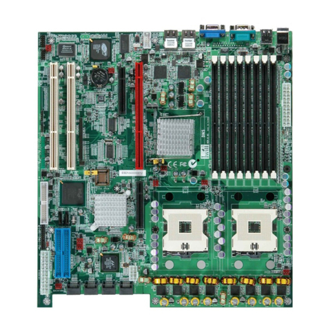
1.1 Motherboard Layout
1.1.1 Components
1.2 Chipset
1.3 C U Socket
1.4 System Memory
1.5 Expansion Slots
1.5.1 AGP slot
1.5.2 PCI slots
05
06
06
06
06
07
08
09
10
10
11
12
13
14
15
16
17
18
18
19

3
1.6 Rear anel I/O orts
1.6.1 PS/2 Keyboa d and PS/2 Mouse Po ts
1.6.2 Pa allel Po t
1.6.3 Se ial Po t
1.6.4 Rea Out and Cente Out Jacks
1.6.5 S/PDIF Out Jack
1.6.6 LAN Po t
1.6.7 USB Po t
1.6.8 Audio Jacks
1.7 SATA Connectors
1.8 IDE Drive Connectors
1.9 Floppy Disk Drive Connectors
1.10 SMBus Connector
1.11 Front anel Connector
1.12 E S12V ower Connector
20
20
21
22
23
24
25
26
27
28
29
31
31
32
34

4
Chapter 2
Hardware Installation
2.1 Jumper Settings
2.1.1 Clea CMOS -JP1
2.1.2 BIOS Flash P otect - JP16
2.2 Motherboard Installation
2.2.1 Installing the Xeon CPU @ 533MHz FSB
2.2.2 Installing the Xeon CPU @ 800MHz FSB
2.3 Memory Installation
Chapter 3
BIOS
Overview
STARTING THE BIOS SETU
USING THE BIOS SETU UTILITY
IM ORTANT
3.1 Main Menu
3.2 Advanced CI / n Settings
3.3 Boot Menu
3.4 Specification
35
36
36
37
38
40
44
46
48
49
50
51
52
53
54
57
58
Index

5
FCC Guidelines
This equipment has been tested and found to comply with the limits
fo a Class B digital device, pu suant to Pa t 15 of the FCC ules. These
limits a e designed to p ovide easonable p otection against ha mful
inte fe ence in a esidential installation. This equipment gene ates, uses
and can adiate adio f equency ene gy and, if not installed and used
in acco dance with the inst uctions may cause ha mful inte fe ence to
adio communications. Howeve , the e is no gua antee that
inte fe ence will not occu in a pa ticula installation. If this equipment
does cause ha mful inte fe ence to adio o television eception, which
can be dete mined by tu ning the equipment off and on, the use is
encou aged to t y to co ect the inte fe ence by one o mo e of the
following measu es:
Reo ient o elocate the eceiving antenna.
Inc ease the sepa ation between the equipment and the eceive .
Connect the equipment into an outlet on a ci cuit diffe ent f om
that to which the eceive is connected.
Consult the deale o an expe ienced adio TV technician fo help.
Use only shielded cables to connect I/O devices to this
equipment.
This device complies with Pa t 15 of the FCC Rules. Ope ation is
subject to the following two conditions:
(1) This device may not cause ha mful inte fe ence.
(2) This device must accept any inte fe ence eceived, including
inte fe ence that may cause undesi ed ope ation.

6
Information to User:
Any changes o modifications not exp essly app oved by the pa ty
esponsible fo compliance could void the use 's autho ity to ope ate
this equipment. Shielded inte fe ence cable, if any, must be used in
o de to comply with emission limits.
Disclaimer of Warranties
The info mation in this document is subject to change without notice.
The manufactu e makes no ep esentatives o wa anties with espect
to the contents he eof and specifically disclaims any implied wa anties
of me chantability o fitness fo any pa ticula pu pose. Fu the mo e, the
manufactu e ese ves the ight to evise this publication and to make
changes f om time to time in the content he eof without obligation of
the manufactu e to notify any pe son of such evision o changes.
Copyright
This publication, including all photog aphs, illust ations and softwa e,
is p otected unde inte national copy ight laws, with all ights ese ved.
Neithe this manual, no any of the mate ial contained he ein, may be
ep oduced without the exp ess w itten consent of the copy ight
holde s. c 2003. All ights ese ved.
Trademark Recognition
Mic osoft and Windows a e egiste ed t adema ks of Mic osoft Co p.
Othe p oduct names used in this manual a e the p ope ties of thei
espective owne s and a e acknowledged.

7
Static Electricity Precautions
It is quite easy to inadve tently damage you PC, mainboa d,
components o devices even befo e installing them in you system unit.
Static elect ical discha ge can damage compute components
without causing any signs of physical damage. You must take ext a
ca e in handling them to ensu e against elect ostatic build-up.
1. To p event elect ostatic build-up, leave the device in its antistatic
bag until you a e eady to install it.
2. Wea an antistatic w ist st ap.
3. Do all p epa ation wo k on a static-f ee su face.
4. Hold the device only by its edges. Be ca eful not to touch any of
the components, contacts o connections.
5. Avoid touching the pins o contacts on all modules and
connecto s. Hold modules o connecto s by thei ends.
Elect ostatic discha ge (ESD) can damage you p ocesso , disk d ive
and othe components. Pe fo m the upg ade inst uction p ocedu es
desc ibed at an ESD wo kstation only. If such a station is not available,
you can p ovide some ESD p otection by wea ing an antistatic w ist
st ap and attaching it to a metal pa t of the system chassis. If a w ist
st ap is unavailable, establish and maintain contact with the system
chassis th oughout any p ocedu es equi ing ESD p otection.

8
Package Contents
The mothe boa d package includes the following items:
DH800 mothe boa d
ATA-66/100 IDE cable
Se ial ATA cable + SATA powe cable
Floppy disk d ive cable
Rea panel I/O shield
Two heat sink etention modules
3 jumpe caps (Ext a caps in case o iginal caps get lost.)
CD (contains d ive s and utilities)
Use 's manual
If any of these items a e missing o damaged, please contact you
deale o sales ep esentative fo assistance. Befo e you p oceed,
please ead the " EPS 12V Powe Connecto s "section in this chapte .
This section contains info mation about the type of powe supply that
you must use with this mothe boa d.

9
Before Using the Motherboard...
Befo e you install and use the mothe boa d, please check the
following:
Package contents
Make su e the package contains all items listed above. If any of
these items a e missing, please contact you deale o sales
ep esentative fo assistance.
Damaged accesso ies
If any of the items a e damaged, please contact you deale o sales
ep esentative fo assistance.
Mothe boa d damage
If the mothe boa d has been visibly damaged, etu n the complete
package to you deale with the p oof of pu chase.
P epa e basic system components
If you a e installing the mothe boa d in a new system, you will need
at least the following inte nal components.
- An Intel RXeonTM CPU
- At least two DDR SDRAM memo y module
- Sto age devices such as ha d disk d ive, CD-ROM, etc.
You will also need whateve exte nal system pe iphe als you intend
to use which will no mally include at least a keyboa d, a pointing
device and a video display monito .

10
Handling the Motherboard
It is quite easy to inadve tently damage the mothe boa d even
befo e installing it in you system unit. Elect ostatic discha ge can
damage compute components without causing any signs of physical
damage. You must take ext a ca e in handling the mothe boa d to
ensu e that no static build-up is p esent.
Tips in Handling the Motherboard
1. To p event elect ostatic build-up, leave the mothe boa d in its
anti-static bag until you a e eady to install it.
2. Do all p epa ation wo k on a static-f ee su face with mothe boa d
components facing up.
3. Hold the mothe boa d by its edges only. Be ca eful not to touch any
of the components, contacts o connections, especially gold
contacts, on the boa d.

11
Quick Installation Guide
Step 1
Install the CPU, CPU fan / heatsink and othe system fans.
Step 2
Install the DIMM.
Step 3
Install add-in ca ds.
Step 4
Configu e the jumpe s.
Step 5
Connect the floppy disk d ive cable and IDE disk d ive cable to thei
espective devices.
Step 6
Connect the powe supply's cables to the app op iate connecto s and
devices.
Step 7
Connect devices to the po ts located at the ea panel.
Step 8
Connect the f ont panel cables (LED indicato s and switch connecto s)
to the f ont panel connecto s.
Step 9
Powe on the PC.
Step 10
Configu e the BIOS.
Step 11
Reboot the PC.
Step 12
Install the d ive s and utilities that a e in the p ovided CD.


13
1.1 Motherboard Layout
EPS 12V Powe Connecto
Mounting Hole
CPU FAN1
CPU
FAN2
AUX_IN
CD_IN
1394 Connecto
SYSFAN 1 WOL JP1
Case Open
SYSFAN 2
FDC
SMBUS
JP3A
& JP3
JP16
F ont Panel
IDE
DIMM Slots
SATA

14
1.1.1 Components
Desc iption Location
CPU Sockets CPU1 , CPU2
Channel A DIMM slots A1 (J5) , A2 (J6)
Channel B DIMM slots B1 (J3) , B2 (J4)
AGP J11
PCI 1 , PCI 2 J12 , J13
PCI-X 1, PCI-X 2 J14 , J15
EPS 12V (24 pin) J37
EPS 12V (8 pin) J37A
CPU Fan 1 J39
CPU Fan 2 J39A
System Fan 1 J41
System Fan 2 J41A
System Fan 3 J41B
CD_IN J54
AUX_IN J53
WOL (Wake-On-LAN) J46
IRDA J45
SMBUS J48
SATA 1 J63
SATA 2 J64
1394 Connecto J67
F ont Panel J43
CPU FSB JP3 , JP3A
FWH P otection JP16
Clea CMOS JP1
Case Open J42
FDC J30
IDE 1 J28
IDE 2 J29

15
1.2 Chipset
Intel Chipset
No th b idge: Intel 875P Memo y Cont olle Hub
South b idge: Hance Rapid I/O Cont olle Hub
Intel LAN Controller
Intel 82547GI Gigabit Ethe net Cont olle
T.I. IEEE-1394 Controller
T.I. TSB43AB22A Cont olle
Suppo t 1394a specification
Analog Devices Audio Controller
Analog Devices AD1980 Cont olle
Suppo t 6-channel audio function
Super I/O Controller
Winbond W83627THF

16
1.3 C U Socket
Function
The two CPU sockets a e fo installing Intel Xeon p ocesso s.
System Bus: 100/133/166/200 MHz
Suppo ts P estonia co e CPU
Auto detect CPU type fo exte nal clock and multiplie settings
Installation Notes
You can install eithe one o two CPUs
When installing one CPU, install it in CPU1 socket
When installing two CPUs, make su e to use identical CPUs. The CPU
settings (clock speed and atio) must also be identical.
C U Installation
Refe to Chapte 2 fo info mation on the CPU installation p ocedu e
BIOS Settings
The BIOS automatically detects the CPU clock. You can manually
configu e the settings in the IWILL Sma t Setting submenu of the BIOS.
Refe to chapte 3 fo mo e info mation.

17
1.4 System Memory
Function
The DIMM sockets a e fo installing DDR SDRAM memo y modules. The
sockets function independently allowing a va iety of configu ations:
Fou DDR DIMM sockets
Suppo t dual channel memo y inte face
Each channel suppo ts 2 DIMM sockets
PC1600 (DDR200) / PC2100 (DDR266) / PC2700 (DDR333) / PC3200
(DDR400) DDR SDRAM modules
Suppo t Unbuffe ed ECC / Non-ECC memo y modules
Suppo t maximum of 4GB memo y using 64, 128, 256, 512 MB o 1GB
technology
Peak memo y bandwidth: 6.4 GB/s
Memo y Configu ation
Suppo t 128MB, 256MB, 512MB, 1GB modules
Modules must all be the same type and capacity
Install only 2 o 4 DIMMs; DO NOT install 3 DIMMs
The fou DDR DIMM sockets a e divided into 2 channels:
Channel A: DIMM A1 (J5) and A2 (J6)
Channel B: DIMM B1 (J3) and B2 (J4)
The figu es below illust ate the ONLY allowed module configu ation.
B1B2 A1 A2

18
1.5 Expansion Slots
1.5.1 AG slot
Function
The AGP slot is fo installing an AGP inte face video display ca d. It is
AGP 3.0 compliant. The slot suppo ts th ee types of AGP ca ds:
AGP 8x (2.13GB/sec bandwidth)
AGP 4x (1066MB/sec. bandwidth)
AGP P o 50 (The slot is extended to suppo t AGP P o ca ds that use
up to 50 watts of powe )
The AGP slot only supports 1.5V devices. DO NOT
install 3.3V AGP card.
BIOS Setting
Configu e the amount of system memo y the AGP ca d will use as
auxilia y memo y by selecting the AGP Ape tu e Size in the Advanced
Chipset Featu es submenu of the BIOS. Refe to chapte 3 fo mo e
info mation.
Display Driver
If the AGP ca d comes with a display d ive , you must install the d ive
acco ding to the documentation that came with it.
AGP 8X / P o J11

19
1.5.2 CI slots
Function
This mothe boa d has fou Bus Maste capable PCI expansion slots,
including two 32-bit 33MHz slots and two 64-bit PCI-X slots ope ating at
66MHz.
BIOS Settings
The BIOS automatically configu es Plug and Play and othe PCI bus
settings. Basically, you do not need to change any esou ce settings
unless you encounte a p oblem afte installing an expansion ca d. You
can econfigu e the settings in the PnP/PCI Configu ations submenu of
the BIOS. Refe to chapte 3 fo mo e info mation.
J13
J14
J15
J12

20
1.6 Rear anel I/O orts
1.6.1 S/2 Keyboard and S/2 Mouse orts
Function
The PS/2 mouse (G een) and PS/2 keyboa d (Pu ple) po ts a e fo
connecting a PS/2 mouse and PS/2 keyboa d espectively. The PS/2
mouse po t uses IRQ12. If a mouse is not connected to this po t, the
system will ese ve IRQ12 fo othe expansion ca ds.
Make sure to turn o your computer prior to connecting or
disconnecting a mouse or keyboard. Failure to do so may damage the
motherboard.
Keyboard/Mouse ower Up Function
You can configu e the system to use the keyboa d o mouse to powe -
on the system. To use this function: " Powe On Function " ( " Supe IO
Device "field) in the Integ ated Pe iphe als submenu of the BIOS must
be set acco dingly. Refe to chapte 3 fo mo e info mation.
Mouse
Keyboa d
Table of contents
Other IWILL Motherboard manuals

IWILL
IWILL LE370 User manual

IWILL
IWILL Motherboard DJ800 User manual

IWILL
IWILL VD133 User manual

IWILL
IWILL P6NS User manual

IWILL
IWILL KK266plus-R Original operating instructions

IWILL
IWILL P55TV User manual

IWILL
IWILL DN800-SATA User manual

IWILL
IWILL piils User manual

IWILL
IWILL DP400 User manual

IWILL
IWILL VD133 Pro Series User manual

IWILL
IWILL DK8N User manual

IWILL
IWILL BD100 Plus User manual

IWILL
IWILL KD266 User manual

IWILL
IWILL KK266Plus User manual

IWILL
IWILL Motherboard DJ800 User manual

IWILL
IWILL MPX2 User manual

IWILL
IWILL FB24624100 User manual

IWILL
IWILL KK400 Series User manual
IWILL
IWILL DVD266 User manual
IWILL
IWILL mP4G2 Series User manual