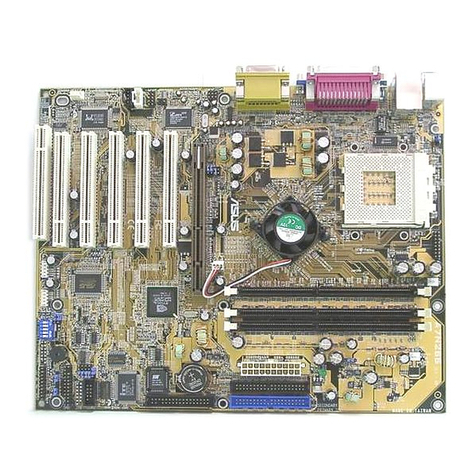
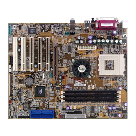
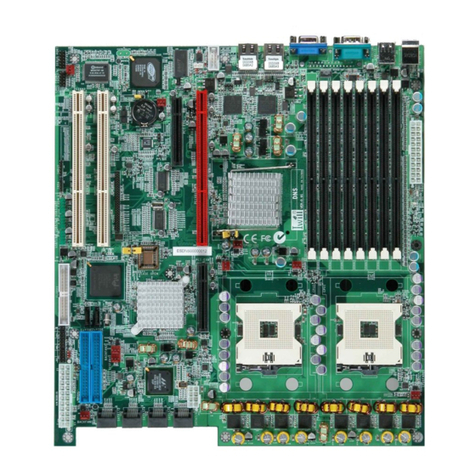
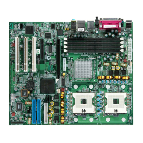
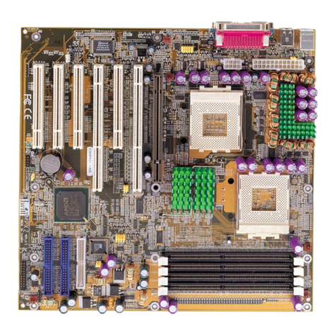
IWILL DN800 User manual

IWILL DN800/DNSV
Motherboard
User’s Manual
FB23634300

User’s Manual
DN800 Motherboard
ii

Preface
Disclaimer
The manufacturer makes no representations or warranties regarding the
contents of this manual and specifically disclaims any implied warranties
of merchantability or fitness for any particular purpose. Furthermore, the
manufacturer reserves the right to revise this publication or make changes
in the specifications of the product described within it at any time without
notice and without obligation to notify any person of such revision or
change.
Trademarks
Microsoft and Windows are registered trademarks of Microsoft Corp.
Intel and Xeon are registered trademarks of Intel Corporation. Other prod-
uct names used in this manual are the properties of their respective owners
and are acknowledged.
Copyright
This publication, including all photographs, illustrations and software,
is protected under international copyright laws, with all rights reserved.
Neither this manual, nor any of the material contained herein, may be re-
produced without the express written consent of the manufacturer. IWILL
©Copyright 2004
Important
The information in this document is subject to change without notice.
iii

User’s Manual
DN800 Motherboard
1: Overview .............................................................................1-1
Packing list ................................................................................. 1-1
Safety Notice.............................................................................. 1-2
DN800/DNSV Specification ..................................................... 1-5
2: Components and Jumper Setting ..........................2-1
Mainboard Map.......................................................................... 2-1
Components List........................................................................ 2-2
Jumper Setting ........................................................................... 2-3
Rear Panel I/O Ports .................................................................. 2-5
Additional I/O Connectors ........................................................ 2-9
EPS12V Power Connectors ..................................................... 2-14
Primary IDE Connectors ......................................................... 2-15
CPU/ System Fan Connectors ................................................. 2-16
3: Hardware Installation ..................................................3-1
Motherboard Installation ........................................................... 3-1
Installing the CPU and Heatsink Procedures ............................ 3-2
Heatsink Installation Notice ...................................................... 3-8
Memory Installation Procedure ................................................. 3-9
Installing Expansion Cards ........................................................ 3-12
Powering on your System.......................................................... 3-13
T
able
o
f
C
ontents
iv

Preface
4: BIOS Setup .........................................................................3-1
Starting the BIOS Setup ............................................................ 4-1
Using the BIOS Setup Utility .................................................... 4-3
Main Menu................................................................................. 4-5
Advanced Menu ......................................................................... 4-6
Boot Menu ................................................................................. 4-7
Boot Setting Configuration Submenu ....................................... 4-8
Exit Menu ................................................................................ 4-10
5: OS and rivers Installation .......................................5-1
OS Installation ........................................................................... 5-1
Drivers Installation .................................................................... 5-2
5:
v

Chapter 1
Overview

Chapter 1
Package
DN800/ DNSV Motherboard
Rear panel I/O shield
Three jumper caps (Extra caps in case original caps get lost)
One Power Installation CD (contains drivers and utilities)
User’s manual
One ATA-66/100 IDE cable
Two SATA cables + one SATA power cable
One Floppy disk drive cable
Two heatsink retention modules
Two Hat Springs for CPU cooler
One Iron backplate
Two CPU Plastic backplates
1-1

Overview
DN800 Motherboard
O v e r v i e w
YOU MUST HAVE ENOUGH SYSTEM INTEGRATION KNOWLEDGE
BEFORE THE INSTALLATION
General Safety Precautions
Keep the area around the Server clean and free of clutter.
Servers weigh a lot. When lifting the system, two people should
lift slowly from opposite ends with their feet spread out to distrib-
ute the weight. Always keep your back straight and lift with your
legs.
Place the chassis top cover and any system components that have
been removed away from the system or on a table so that they won’t
accidentally be stepped on.
While working on the system, do not wear loose items such as neck-
ties and unbuttoned shirtsleeves. They can come into contact with
electrical circuits or get pulled into a cooling fan.
Remove any jewelry or metal objects from your body, which are
excellent metal conductors and can create short circuits and harm
you if they come into contact with printed circuit boards or areas
where power is present.
ESD Precautions
Electrostatic discharge (ESD) is generated by two objects with dif-
ferent electrical charges coming into contact with each other. An elec-
trical discharge is created to neutralize this difference, which can dam-
age electronic components and printed circuit boards. The following
measures are generally sufficient to neutralize this difference before
contact is made to protect your equipment from ESD:
1-2

Chapter 1
Use a grounded wrist strap designed to prevent static discharge.
Keep all components and printed circuit boards (PCBs) in their
antistatic bags until ready for use.
Touch a grounded metal object before removing the board from
the antistatic bag.
Do not let components or PCBs come into contact with your
clothing, which may retain a charge even if you are wearing a wrist
strap.
Handle a board by its edges only; do not touch its components,
peripheral chips, memory modules or contacts.
When handling chips or modules, avoid touching their pins.
Put the motherboard and peripherals back into their antistatic bags
when not in use.
For grounding purposes, make sure your computer chassis provides
excellent conductivity between the power supply, the case, the
mounting fasteners and the motherboard.
After accessing the inside of the system, close the system back up
and secure it to the rack unit with the retention screws after ensur-
ing that all connections have been made.
Operating Precautions
Check package contents
Missing or damaging accessories
Please contact your vendor immediately
Motherboard damage
Please contact your vendor immediately
Prepare minimum system components
Intel Xeon @800MHz FSB Processor
At least one Registered DDR memory module
At least one SATA or IDE HDD
EPS12V Power Supply with 460W or above
1-3
Overview
DN800 Motherboard
O v e r v i e w
Getting Help
If a problem arises with your system during Installation or Operation,
you should first ask your dealer for help as they have most likely config-
ured your system. They generally have the best grasp of your issues and
the fastest response for your symptoms. If your dealer is near your location,
it is recommended that you first bring your system to them to have it ser-
viced instead of attempting to solve the problem yourself.
If those options don’t work for you, IWILL also provides some helpful
resources to help you.
1. Visit IWILL®website at http://www.iwill.net and navigate to this
product’s page which contain links to product updates such as Jumper
settings or BIOS updates.
2. The FAQ (Frequently Asked Questions) sections in the IWILL
website are often helpful since other users often have the same
questions.
tions within 5 business days.
1-4

Chapter 1
DN800/ DNSV Specifications
Processor Intel®Dual Xeon Socket 604 CPUs
Supports 800MHz FSB
Chipset
DN800—Intel E7525 Chipset MCH
DNSV— Intel E7320 Chipset MCH
Intel Hance Rapids ICH
Winbond 83627HF
ATi Rage XL
Memory
4 DIMMs for 184-pin DDR DIMM sockets
Uses Registered DDR266/333 with ECC or Non-ECC
memory
Supports total system memory size of up to 8GB
Graphics
One x16 PCI Express slot for graphics (DN800 ONLY)
ATi Rage XL VGA with 8M RAM on board
Dual Gigabit Ethernet Controller
Intel 82541PI
Boardcom BCM5721
Two RJ-45 connectors for GbE
Support PME
Integrated Analog Device AD1980
Professional 6-channel Audio
AC ’97 CODEC
USB 2 x external USB 2.0 ports
2 x internal USB 2.0 ports
Serial ATA
2 Serial ATA ports
Support Adaptec Host RAID
Support hot swap
One x16 PCI Express slot for graphics (DN800 ONLY)
One x8 PCI Express slot (with x4 bandwidth)
Two PCI 64-bit / 66 MHz
One PCI 32-bit / 33 MHz
On-Board
LAN
Expansion
Slots
Audio
(DN800 ONLY)
1-5

Overview
DN800 Motherboard
O v e r v i e w
1-6
34-pin Floppy Connector
4-pin CD-In audio input connector (DN800 ONLY)
IDE Bus
2x 40-pin IDE connectors, supports up to
four (4) Enhanced IDE devices
Dual Channel Master Mode
Ultra DMA 100/66/33
Rear Panel I/O
PS/2 mouse and keyboard connectors
1 x UART 16550 serial port (COM1)
1 x 25-pin parallel port with ECP/EPP support
1 x VGA port
2 x on board USB 2.0 ports
2 x Gigabit Ethernet LAN RJ-45 port
Audio Phone Jacks - Line Out, Mic In, Line-In.
Server Management Support IPMI 1.5
Support mBMC by 2x25 pin-header
System BIOS
AMI BIOS
Flash write protection by BIOS
Support console redirection
ACPI 1.1
APM 1.2
Support ACPI S1
Support ACPI S3 (DN800 ONLY)
Support ASF 2.0
System Management
Hardware Monitor control by Winbond 83627HF
Support AC power failure
Form Factor ATX form factor
12”x10”
EPS 12V power connectors (24 pin + 8 pin)
Internal I/O
connector

Chapter 2
Components and Jumper Setting

Hardware InstallationHardware Installation
DN800 Motherboard
Components and Jumper Setting
2-1
MAINBOARD MAP
J57
J48
J50
J64
J65
J43 JP1
J45
J34
PCI 32/33
PCI-X 64/66
PCI-X 64/66
PCI-Express x4
PCI-Express x16 (DN800 Only)
DIMMB2 DIMMA2
DIMMB1
DIMMA1
CPU1CPU2
Floppy
Secondary
Primary
2-1

Chapter 2
Components List
CPU1; CPU2 Intel Xeon Socket604 Processor
Primary; Secondary IDE Driver Connectors
Floppy Floppy Disk Driver Connector
PCI Slots PCI-Express x16, x4 Slots; PCI-X 66; PCI
DIMM B2~A1 Memory Socket for DDR Memory
JP1 Clear CMOS Header
J34 USB 2.0 Ports and Header
J43 Front Panel Switch Header
J45 IrDA Connector
J48 SMBus Connector
J50 IPMI connector
J57 Front Audio Jumper
J64, J65 Serial ATA Connector
2-2

Hardware InstallationHardware Installation
DN800 Motherboard
Components and Jumper Setting
2-3
Jumper Setting
JP1: Clear CMOS Header
The onboard button cell battery powers the CMOS RAM. It con-
tains all the BIOS setup information. Keep the jumper connected to
pins 1-2 (Default) to retain the RTC data as shown below.
Under certain circumstances, you will need to reset system settings.
Follow these instructions to clear the CMOS RTC data:
1. Turn off the computer.
2. Short pins 2 and 3 with a jumper for a few seconds.
3. Replace the jumper to pins 1 and 2.
4. Turn on your computer by pressing the power-on button.
5. Hold down <F2> during boot and select either <Load Optimal
Defaults> or <Load Failsafe Defaults> in the “Exit” section. Then
go through the BIOS setup to re-enter user preferences.
1-2 2-3
Normal (Default) Clear CMOS
1
2
3

Chapter 3
J57: Front Audio Jumper
This header lets you enable or disable the function of the front audio
connector.
2-4
J57
5-6 SHORT OPEN
9-10 SHORT OPEN
W/O FRONT
AUDIO
CONNECTOR
WITH FRONT
AUDIO
CONNECTOR
19
10

Hardware InstallationHardware Installation
DN800 Motherboard
Components and Jumper Setting
PS/2 Keyboard and PS/2 Mouse Ports Function
The PS/2 mouse (Green) and PS/2 keyboard (Purple) ports are for
connecting a PS/2 mouse and PS/2 keyboard respectively. The PS/2
mouse port uses IRQ12. If a mouse is not connected to this port, the
system will reserve IRQ12 for other expansion cards
Rear Panel I/O Ports
Mouse
Keyboard
2-5

Chapter 2
Parallel
Serial COM VGA
Parallel Port Function
The standard parallel port (Burgundy) is for interfacing your PC to a
parallel printer. It supports SPP, ECP and EPP modes.
SPP (Standard Parallel Port)
Allows normal speed operation but in one direction only.
ECP (Extended Capabilities Port)
Allows parallel port to operate in bidirectional mode and at a speed
faster than the SPP’s data transfer rate.
EPP (Enhanced Parallel Port)
Allows bidirectional parallel port operation at maximum speed.
Serial Port Function
The serial ports are RS-232C asynchronous communication ports
with 16C550A-compatible UARTs that can be used with modems, se-
rial printers, remote display terminals, and other serial devices. It can
operate at speeds up to 115,200bps. You can configure the port’s speed
in the computer’s Operating System.
2-6

Hardware InstallationHardware Installation
DN800 Motherboard
Components and Jumper Setting
LAN Port Function
The LAN port uses a CAT 5 LAN cable for connecting the
motherboard to a local area network by means of a network hub. The
port has 2 indicator LEDs.
Speed LED (left)
10Mbps - will not blink
100Mbps - LED is green
1000Mbps - LED is orange
Link and Activity LED (right)
LED is yellow when the LAN connection is linked and accessed.
USB Port Function
The motherboard supports USB 2.0. USB 2.0 supports 480Mb/sec-
ond bandwidth providing a marked improvement in device transfer
speeds between your computer and a wide range of simultaneously ac-
cessible external Plug and Play peripherals.
You can connect or disconnect USB cables when the system is turned
on.
Speed LED Link and Activity LED
LAN
LAN USB
2-7
This manual suits for next models
2
Table of contents
Other IWILL Motherboard manuals

IWILL
IWILL mP4G2 Series User manual

IWILL
IWILL VX133 User manual

IWILL
IWILL dca200 User manual

IWILL
IWILL DPIILS2 User manual

IWILL
IWILL DPX2-S320 User manual

IWILL
IWILL P4GB Series User manual

IWILL
IWILL kv200 User manual

IWILL
IWILL XP333 User manual

IWILL
IWILL DNS-SATA User manual

IWILL
IWILL DN800-SATA User manual