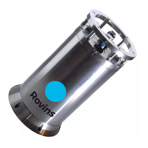
iXBlue ROVINS User manual

Rovins
Installation & Setup Guide


Rovins -Installation & Setup Guide
Revision History
Edition Date Comments
A 07/2019 Creation
B 03/2020 Chapters 5.2.1 & 5.5 updated
MU-ROVINSISG-AN-001-B - March 2020 3

Rovins -Installation & Setup Guide
Copyright
All rights reserved. No part of this manual may be reproduced or transmitted, in any form or by
any means, whether electronic, printed manual or otherwise, including but not limited to
photocopying, recording or information storage and retrieval systems, for any purpose without
prior written permission of iXblue.
Disclaimer
iXblue specifically disclaims all warranties, either expressed or implied, including but not limited
to implied warranties about merchantability and fitness for a particular purpose with respect to
this product and documentation. iXblue reserves the right to revise or to make changes or
improvements to this product or documentation at any time without notify any person of such
revision or improvements.
In no event shall iXblue be liable for any consequential or incidental damages, including but not
limited to loss of business profits or any commercial damages, arising out of the use of this
product.
Trademarks
Microsoft, MS-DOS and Windows are registered trademarks of Microsoft Corporation.
Intel and Pentium are registered trademarks and Celeron is a trademark of Intel Corporation.
Export Control
This product is subject to export control regulations. Please refer to the commercial offer or
contact iXblue for details about the applicable export control regulations and restrictions.
4MU-ROVINSISG-AN-001-B - March 2020

Rovins -Installation & Setup Guide
Rovins Documentation
The following documents give all the information you need in order to understand and to use
your product.
●Rovins Technical Description (ref.: MU-ROVINSTD-AN-001)
>Rovins and iXblue technology presentation
>Technical specifications
>Certification and qualification, life cycle
>Mechanical, electrical and communication interface description
●Rovins Installation & Setup Guide (ref.: MU-ROVINSISG-AN-001)
>Conventions
>Physical and electrical installation
>Connecting to the Web-Based Graphical User Interface
>Setup the Rovins
>Contacting iXblue support
●Rovins Operation Guide (ref.: MU-ROVINSOG-AN-001)
>Introduction to the Inertial Navigation System
>Start-up Phases
>Web-Based Graphical User Interface description
>Configuring the navigation parameters & managing the external information
>Viewing the system information
>Recording data
●Rovins Interface Library (ref.: MU-ROVINSIL-AN-001)
>NMEA frames
>Digital input and output protocols
>Pulses interfaces specification
>Control commands
●Rovins Quick Start Guide
>Pack content verifying
>Installing and connecting Rovins
>Configuring and operating Rovins
●SEACON 12 PIN TI 1M Pigtail Cable - Product Description (Ref.: MU-PDCABLES-
AN-001)
>cable and pinout of the SEACON 12 pins Pigtail Cable
●SEACON 19 PIN TI 1M Pigtail Cable - Product Description (Ref.: MU-PDCABLES-
AN-002)
>cable and pinout of the SEACON 19 pins Pigtail Cable
●SEACON 26 PIN TI 1M Pigtail Cable - Product Description (Ref.: MU-PDCABLES-
AN-003)
>cable and pinout of the SEACON 26 pins Pigtail Cable
●Subsea Products - Illustrated Part Catalog ref.: MU-SUBSEADP-AN-001
>Detailed part list
>Alphanumerical Index
●Application Note - INS+DVL Calibration (ref.: MU-DVLINS-AN-001)
>Configuring the calibration
>Calibrating the DVL+INS
MU-ROVINSISG-AN-001-B - March 2020 5

Rovins -Installation & Setup Guide
●Application Note - Installation and Configuration of AHRS and INS for Seabed
Mapping Measurements (ref.: MU-HEAVAPN-AN-001)
>Using heave compensation on seabed mapping
>Effect of vessel transient movements
6MU-ROVINSISG-AN-001-B - March 2020

Rovins -Installation & Setup Guide
Rovins Installation & Setup Guide Overview
This document must be read and understood prior to using the product.
The manufacturer shall in no case be held liable for any application or use that does not comply
with the stipulations in this manual.
The Rovins Installation & Setup Guide is divided into several parts:
●Part 1: Definition and Conventions
This part gives the definition and conventions used in this document and in the product.
●Part 2: Process to install and enable the system
This part gives a diagram of the steps to be performed in order to install and enable the
system.
●Part 3: Installing the Rovins
This part describes the mechanical and electrical installation of the Rovins and how to
power the Rovins on.
●Part 4: Connecting to the Web-Based Graphical User Interface
This part describes how to connect the Rovins to the Web- Based Graphical User
Interface.
●Part 5: Configuring the Rovins
This part gives the procedures to configure the Rovins with the Web-Based Graphical
User Interface.
●Part 6: Contacting iXblue support
This part describes how to contact iXblue support in case of problem.
●Appendices
Procedures to connect Rovins to a PC by serial link and to use the simulation mode.
MU-ROVINSISG-AN-001-B - March 2020 7

Rovins -Installation & Setup Guide
Abbreviations and Acronyms
ACC Accelerometer
CTD Conductivity, Temperature, Depth sensor
DVL Doppler Velocity Log
EGNOS European Geo-stationary Navigation Overlay Service
Galileo European Satellite Navigation System
GGA Essential fix data which provide 3D location and accuracy data
GLONASS Global Navigation Satellite System (operated by the Russian
Space Forces)
GNSS Global Navigation Satellite System
GPS Global Positioning System (operated by the United States Depart-
ment of Defense)
GST GPS Pseudo-range Noise (PRN) statistics (The GST message is
used to support Receiver Autonomous Integrity Monitoring)
HRP Heading, Roll, Pitch
IMU Inertial Measurement Unit
INS Inertial Navigation System
IP Internet Protocol
LVA Lever Arms
PPS Pulse Per Second
RTK Real Time Kinematic
SD Standard Deviation
UTC International acronym for Coordinated Universal Time (CUT)
UTM Universal Transverse Mercator
VTG Vector Track and speed over Ground
ZDA Time and Date (The ZDA message identifies UTC time, day,
month, and year, local zone number, and local zone minutes)
ZUPT Zero velocity UPdaTe
8MU-ROVINSISG-AN-001-B - March 2020

Rovins -Installation & Setup Guide
Table of Contents
1 DEFINITIONS AND CONVENTIONS 12
1.1 REFERENCE FRAME 12
1.1.1 Rovins Reference Frame 13
1.1.2 subsea vehicle reference frame 14
1.1.3 subsea vehicle horizontal frame 15
1.1.4 Navigation Frame 15
1.2 ATTITUDE AND HEADING 16
1.2.1 Definition of Heading 17
1.2.2 Definition of Roll 18
1.2.3 Definition of Pitch 19
1.3 POSITION DATA 20
1.3.1 Latitude, Longitude and Altitude 20
1.3.2 The UTM Coordinate System 20
1.4 HEAVE, SURGE AND SWAY 21
1.5 SPEEDS 21
1.6 RATES AND ACCELERATIONS 22
1.7 STANDARD DEVIATION DATA 22
1.8 EXTERNAL SENSOR DATA 22
1.9 MISALIGNMENT DEFINITION 23
1.9.1 Rovins to subsea vehicle Rough Misalignment (Rovins Position and Orientation) 23
1.9.2 Rovins to subsea vehicle Fine Misalignment 24
1.9.3 DVL to Rovins Misalignment 28
1.10 OUTPUT LEVER ARMS 29
1.11 CENTER OF GRAVITY (COG) LEVER ARMS 30
2 PROCESS TO INSTALL AND ENABLE THE SYSTEM 31
3 INSTALLING THE ROVINS 32
3.1 PREPARING THE ROVINS SETUP 32
3.2 PACK CONTENT VERIFYING 32
3.3 MECHANICAL INSTALLATION 33
3.3.1 Rovins location requirements 33
3.3.2 Alignment of Rovins to subsea vehicle Reference Frame 33
3.3.3 External Sensor Lever Arm 34
3.3.4 Installation procedure 35
3.4 ELECTRICAL INSTALLATION 36
3.4.1 Rovins electrical interface overview 36
3.4.2 Pre-requisites 36
3.4.3 Ethernet Connector 37
3.4.4 Port A&B Connector (Central Connector) 38
3.4.5 Port X (X being C, D or E) Connector 39
3.4.6 Rovins Power Network 40
3.4.7 Connecting Rovins 41
4 CONNECTING TO THE WEB-BASED GRAPHICAL USER INTERFACE 42
4.1 CONNECTING ROVINS DIRECTLY TO A PC/LAPTOP 42
4.2 LAUNCHING THE WEB-BASED GRAPHICAL USER INTERFACE 45
4.2.1 Required Environments 45
4.2.2 Web-Based Graphical User Interface Version 45
MU-ROVINSISG-AN-001-B - March 2020 9

Rovins -Installation & Setup Guide
4.2.3 Launching the Web-Based Graphical User Interface 46
4.3 CONFIGURING THE LINK BETWEEN A PC AND ROVINS WITH THE WEB-BASED GRAPHICAL USER
INTERFACE 47
5 CONFIGURING THE ROVINS 50
5.1 CONFIGURING THE MECHANICAL PARAMETERS 50
5.2 CONFIGURING SENSOR PARAMETERS 55
5.2.1 Assigning an External Sensor to an Input 55
5.2.2 Configuring the Input 57
5.2.3 Configuring the GNSS Sensor 59
5.2.4 Configuring the DVL Sensor 60
5.2.5 Configuring the EM Log Sensor 62
5.2.6 Configuring the LBL Sensor 63
5.2.7 Configuring the USBL Sensor 64
5.2.8 Configuring the Depth Sensor 65
5.2.9 Configuring the UTC Sensor 67
5.2.10 Configuring the CTD sensor 67
5.2.11 Monitoring the External Sensor Data 68
5.3 CONFIGURING THE INPUT PULSES 69
5.4 CONFIGURING THE OUTPUT PORTS 70
5.5 CONFIGURING THE OUTPUT PULSES 73
5.6 CONFIGURING THE ADVANCED POSITION FILTERING 74
5.7 CONFIGURING THE WARNING 78
5.8 SAVING THE ROVINS SETTINGS 80
5.9 RESTARTING ROVINS 81
5.10 LOADING THE ROVINS SETTINGS 81
5.11 ACTIVATING THE LICENCE CODE 82
5.12 MANAGING THE PASSWORDS 83
6 CONTACTING IXBLUE SUPPORT 86
APPENDICES 87
A ROTATIONAL AND VECTORIAL TRANSFORMATION 87
A.1 VECTORIAL TRANSFORMATION BETWEEN LOCAL GEOGRAPHIC FRAME AND VEHICLE 90
B ADVANCED COMMUNICATION SETUP 91
B.1 CONFIGURING ROVINS IN AN ETHERNET NETWORK 91
B.1.1 Choosing an IP Address 91
B.1.2 Retrieving the IP address of Rovins 92
B.1.3 Testing the connection 93
B.2 SETTING UP THE ROVINS DATA CONNECTION 98
B.2.1 Transport modes 98
B.2.2 Port Numbers 99
B.2.3 Configuring a Port with the TCP Transport Modes 99
B.2.4 Configuring a Port with the UDP Transport Modes 99
B.3 CONNECTING ROVINS DIRECTLY TO A PC/LAPTOP BY SERIAL LINK 100
B.3.1 Access to Network Connection Window 100
B.3.2 Creating a direct connection between Rovins and your PC 101
B.3.3 Activating the New Connection 102
B.3.4 Creating a Serial Direct Connection under Windows 7 103
B.3.5 Rovins Configuration 108
C ENABLING THE SIMULATION MODE 109
10 MU-ROVINSISG-AN-001-B - March 2020

PAGE INTENTIONALLY LEFT BLANK
11 MU-ROVINSISG-AN-001-B - March 2020
Rovins -Installation & Setup Guide

Rovins -Installation & Setup Guide
1 Definitions and Conventions
The conventions given in this part are used in all the documentation of Rovins.
1.1 Reference Frame
Navigation data are given in a reference frame. The reference frame is defined by its center and
3 non coplanar axes (preferably orthogonal).
Following are the various frames that are available on the Rovins .
[I]: inertial
>Earth Centered Inertial Fixed
>It is fixed in space, it points to stars
[N]: Navigation
>Centered on the vessel
>Pointing North West Up
[E]: Earth
>Earth centered, earth fixed
[B]: Body
>Reference attached to the vessel
>Pointing usually Front Left Up (not vertical, orthogonal to
the floor)
MU-ROVINSISG-AN-001-B - March 2020 12

Rovins -Installation & Setup Guide
1.1.1 ROVINS REFERENCE FRAME
The Rovins reference frame center, P, is the reference point for the determination of Rovins and
external sensor lever arms. The Rovins reference frame center P is the intersection of the three
Rovins reference axis X1, X2 and X3.
Axis definition When horizontal, three orthogonal axes define a reference frame as follows:
●Axis X1is in the product horizontal plane. It is parallel to the thin shape arrow going from the
rear side to the front side.
●Axis X3is vertical and perpendicular to the Rovins horizontal plane, going from the bottom
and pointing upward.
●Axis X2is in the horizontal plane, perpendicular to X1, pointing to the left of the product (top
view): X2= X3 ^ X1
Figure 1 - Definition of axis X1, X2 and X3 and sides
Face Definition The faces are defined in the figure above.Sign convention is indicated on the top face. The
three axes intersect at point P, which is the Rovins reference point.
The logo side and the connector side are used in the installation procedure to configure the
inertial product orientation with respect to subsea vehicle (rough misalignment).
13 MU-ROVINSISG-AN-001-B - March 2020
Rovins -Installation & Setup Guide
1.1.2 SUBSEA VEHICLE REFERENCE FRAME
The vehicle reference frame is defined by the three orthogonal axes XV1, XV2 and XV3 (see
Figure 2):
This frame is used to specify sensor lever arms. Computed data are output in this reference
frame on main and secondary lever arms.
Figure 2 - Definition of the subsea vehicle reference frame
Important
Some applications use different axes conventions (i.e. Vertical axis pointing downward, side
axes pointing right …). Special caution must be taken to use the Rovins convention during the
installation process.
MU-ROVINSISG-AN-001-B - March 2020 14
Rovins -Installation & Setup Guide
1.1.3 SUBSEA VEHICLE HORIZONTAL FRAME
This is the subsea vehicle frame compensated from roll and pitch. (XVH1 and XVH2 are in the
horizontal plane). It is defined by the three orthogonal axes XVH1, XVH2 and XVH3.
This frame is used to output heave, surge, sway and associated speeds.
It is also used to output longitudinal and transverse speed data.
1.1.4 NAVIGATION FRAME
The navigation frame is the local geographic frame defined by the three axes (see Figure 3):
●XN, in the local horizontal plane, pointing towards North
●XW, in the local horizontal plane, pointing towards West
●Xup, parallel to the local vertical, pointing up
Figure 3 - Definition of the navigation frame
15 MU-ROVINSISG-AN-001-B - March 2020

Rovins -Installation & Setup Guide
1.2 Attitude and Heading
The angular position of the vehicle is provided in roll, pitch and heading coordinates.
Roll, pitch and heading come from the rotational transformation between the subsea vehicle’s
frame (XV1, XV2, XV3) and the local geographic frame XN, XW, XUp).
This rotational transformation is fully described in Appendix and is illustrated in the figure
below with positive heading and roll angles and negative pitch angle.
Figure 4 - Definition of heading (H), roll (R) and pitch (P)
The three next sections give the definitions of heading, pitch and roll. They also give simplified
situations for a better understanding.
MU-ROVINSISG-AN-001-B - March 2020 16

Rovins -Installation & Setup Guide
1.2.1 DEFINITION OF HEADING
Figure 5 gives a simplified description when pitch and roll are null, and no misalignment is taken
into account.
Heading varies from 0 to 360 degrees.
Figure 5 - Definition of heading angle in case of null pitch and roll, and no misalignment
17 MU-ROVINSISG-AN-001-B - March 2020
Rovins -Installation & Setup Guide
1.2.2 DEFINITION OF ROLL
Roll is the angular rotation around the XV1 subsea vehicle axis which transforms the subsea
vehicle axis XV2 into XV2h.
XV2h is included into the local horizontal plane defined by vectors XNand XW.
Roll is counted positively when turning counter-clockwise around XV1.
That means that the roll is counted positive when subsea vehicle port side is up.
Roll varies from -180 up to +180 degrees.
Figure 6 shows a simplified description of roll when heading and pitch are null and no
misalignment is accounted for.
Figure 6 - Definition of the roll angle in case of null heading and pitch, and no misalignment
MU-ROVINSISG-AN-001-B - March 2020 18

Rovins -Installation & Setup Guide
1.2.3 DEFINITION OF PITCH
Pitch is the angle between the XV1 subsea vehicle axis and XV1h.
XV1h is the XV1 axis projection in the local horizontal plane defined by the two vectors XNand
XW.
Pitch is counted positively from the local horizontal plane to the XV1 axis when turning counter-
clockwise around XV2.
That means that the pitch is positive when the vessel’s bow’s front is down.
The Figure 7 gives a simplified description when heading and roll are null, and no misalignment
is accounted for.
Pitch varies from – 90 up to + 90 degrees.
Figure 7 - Definition of pitch angle in case of null heading and roll, and no misalignment
19 MU-ROVINSISG-AN-001-B - March 2020

Rovins -Installation & Setup Guide
1.3 Position Data
Rovins position is available in usual latitude/longitude/altitude/depth format and in UTM
(Universal Transverse Mercator) format.
The reference ellipsoid is WGS 84 ellipsoid.
1.3.1 LATITUDE, LONGITUDE AND ALTITUDE
The conventions are:
Latitude
Convention ●For latitude (degrees):
>Northern hemisphere latitudes are positive (0 to 90 degrees)
>Southern hemisphere latitudes are negative (– 90 to 0 degrees)
Longitude
Convention ●For longitude (degrees):
>Longitude ranges from 0 to 360 degrees. Longitude zero is the Greenwich meridian and
longitude is positive going eastwards.
>Longitude can be entered manually into the Rovins Web- Based Graphical User
Interface, either from 0 to 360 degrees or from –180 to +180 degrees. Whatever the
format of the manually entered longitude, it will be displayed in the Web-Based
Graphical User Interface windows as a positive number from 0 (Greenwich meridian) to
360 degrees.
For instance, if a longitude of –30 degrees is entered manually, it will be displayed as
330 degrees in the Web-Based Graphical User Interface.
Altitude
Convention ●For altitude (meters): conventions depend on Rovins, on the output protocol settings and
the selected altitude mode. Refer to the altitude modes described in the Rovins Operation
Guide.
1.3.2 THE UTM COORDINATE SYSTEM
The UTM coordinate system is made up of 60 vertical (north/south) zones starting at 180
degree longitude meridian and wrapping around the earth towards East.
Each zone is 6 degree wide and is numbered from 1 to 60.
The system is further divided into 20 horizontal (east/west) bands starting at -80 degrees south
latitude with band labeled ‘C” and ending north at +84 degrees latitude with band “X” (the letters
“I” and “O” are not used to avoid confusion with numbers).
Inside each UTM zone, the coordinates of a point on the earth are expressed by two values in
meters: UTM Northing and UTM Easting.
These coordinates are obtained by local projection of the earth on a cylinder.
This kind of projection ensures that the deformation due to plane projection is minimized.
The UTM Northing and Easting coordinates are always positive.
MU-ROVINSISG-AN-001-B - March 2020 20
Other manuals for ROVINS
2
Table of contents
Other iXBlue Marine Equipment manuals
Popular Marine Equipment manuals by other brands

NKE
NKE HR Masthead unit USER GUIDE and INSTALLATION GUIDE

Klaxon
Klaxon Nexus 110 DC installation instructions

CanDock
CanDock G2 JETSLIDE Installation and use

Furuno
Furuno FCV-271 Operator's manual

auto maskin
auto maskin Marine Pro 200E Series installation manual

Cyclops Marine
Cyclops Marine smarttune Guide