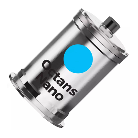
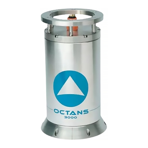
iXBlue Octans User manual

O CTA N S
5th generation
User Manual


OCTANS – User Manual
MU-OCTANS-AN-020 Ed. D – November 2015
1
Document Revision History
Edition Date Comments
A 03/2015 First Edition
B 04/2015 Certification chapter updated. Repeater connector pinout updated.
C 09/2015 Certification and outputs sections updated
D 11/2015 Mechanical figure updated

OCTANS – User Manual
MU-OCTANS-AN-020 Ed. D – November 2015
2
Copyright
All rights reserved. No part of this guide may be reproduced or transmitted, in any form or
by any means, whether electronic, printed guide or otherwise, including but not limited to
photocopying, recording or information storage and retrieval systems, for any purpose
without prior written permission of iXBlue.
Disclaimer
iXBlue specifically disclaims all warranties, either express or implied, included but not
limited to implied warranties of merchantability and fitness for a particular purpose with
respect to this product and documentation. iXBlue reserves the right to revise or make
changes or improvements to this product or documentation at any time without notify any
person of such revision or improvements.
In no event shall iXBlue be liable for any consequential or incidental damages, including
but not limited to loss of business profits or any commercial damages, arising out of the
use of this product.

OCTANS – User Manual
MU-OCTANS-AN-020 Ed. D – November 2015
3
Text Usage
bold
Bold text is used for items you must select or click in the
software. It is also used for the field names used into the dialog
box.
Courier
Text in this font denotes text or characters that you should enter
from the keyboard, the proper names of disk Drives, paths,
directories, programs, functions, filenames and extensions.
italic
Italic text is the result of an action in the procedures.
Icons
The Note icon indicates that the following information is of interest to the operator and
should be read.
The Caution icon indicates that the following information should be read to forbid or
prevent product damage.
The Warning icon indicates that possible personal injury or death could result from failure
to follow the provided recommendation.
Abbreviations and Acronyms
Abbreviations and acronyms are described in the document Inertial Products - Principle &
Conventions (Ref.: MU-INS&AHRS-AN-003).

OCTANS – User Manual
MU-OCTANS-AN-020 Ed. D – November 2015
4
Table of Contents
1INTRODUCTION.............................................................................................................. 5
2PRODUCT DOCUMENTATION .......................................................................................... 6
3VERIFICATION OF PACK CONTENTS................................................................................ 8
4CERTIFICATION ............................................................................................................. 9
5MECHANICAL SPECIFICATIONS..................................................................................... 10
5.1 OCTANS MECHANICAL ALIGNMENT..........................................................................................10
5.2 OCTANS CENTER OF MEASUREMENT.......................................................................................10
6ELECTRICAL INTERFACE SPECIFICATION ...................................................................... 13
6.1 GENERAL OVERVIEW.................................................................................................................13
6.1.1 Outputs...............................................................................................................................13
6.1.2 Inputs .................................................................................................................................14
6.2 DESCRIPTION OF THE CONNECTOR PANEL .................................................................................14
6.3 LISTING OF INTERFACES ............................................................................................................15
6.4POWER SUPPLY CONNECTOR....................................................................................................16
6.5 REPEATER AND CONFIGURATION CONNECTOR ...........................................................................17
6.6 DIGITAL CONNECTOR ................................................................................................................18
6.6.1 Digital Connector Pin Out ..................................................................................................18
6.6.2 Definition of the 2 Inputs and 3 Outputs in RS232 Format................................................20
6.6.3 Definition of the 2 Inputs and 3 Outputs in RS422 Format................................................20
6.6.4 Definition of the 4 Pulse Inputs and 2 Pulse Outputs ........................................................21
6.6.5 Definition of the Configuration and Repeater I/O Signal....................................................22
6.7 ETHERNET CONNECTOR ............................................................................................................23
6.8 RECOMMENDED WIRINGS ..........................................................................................................24
6.9 SPECIFICATIONS FOR COMMUNICATION BETWEEN OCTANS &PC.................................................27

OCTANS – User Manual
MU-OCTANS-AN-020 Ed. D – November 2015
5
1 INTRODUCTION
This document is the OCTANS User Manual. It provides information on OCTANS
specifications, mechanical and electrical interfaces.
OCTANS is both a fiber-optic survey-grade IMO-certified gyrocompass and a Motion
Reference Unit for marine applications. OCTANS provides true-heading, roll, pitch, yaw,
heave, surge, sway, rates of turn and accelerations even in highly volatile environments.
•GPS
•Speed log
OCTANS can output two distinct heave measurements:
•Real Time Heave which provides heave in real time mode.
•Smart HeaveTM which provides a measurement of heave with a 100s fix delay.
To avoid the effect of transient vehicle/vessel movement on heave measurement, you can
define the position of the center of gravity (COG) of the vehicle/vessel. In this case,
OCTANS will compute heave at the COG and add the heave induced by lever arms from
the COG to external monitoring points. For more details see:
•Inertial Products – Application Note - Installation and Configuration of AHRS and INS
for Seabed Mapping Measurements (Ref.: MU-HEAVAPN-AN-001)
•Inertial Products – Web-based Interface User Guide (ref.:MU-INSIII-AN-021)
Your OCTANS internal clock can be synchronized with data coming from an external
reference clock (e.g. GPS clock). In this case, time is synchronized with input coming from
the selected interface with appropriate protocol.
For more details see Inertial Products – Web-based Interface User Guide (ref.:MU-INSIII-
AN-021).
To maintain the product watertightness and EMC specification (see Technical
Specifications for level applicable to your product), it is mandatory to use the provided
connectors and adequate cables. If connector is not used, then it must be
protected/closed with the supplied screwed dummy plugs.
Do not expose to water or humidity if an “office type” Ethernet connector is directly
plugged into OCTANS, use instead, the provided Ethernet connector with its backshell.
When applicable (i.e. IMO Product), OCTANS unit complies with the requirements of the
IEC 60945 standard, including §4.5: interference. As recommended in §4.5.3 - Compass
Safe distance, the minimum safe distance at which OCTANS shall be mounted from a
standard or a steering magnetic compass is 5 meters.
Supported
sensors
Heave
measurement/
Center of
Gravity of the
vehicle (COG)
UTC/Time
synchro
Waterproof and
Electroma-
gnetic
Compatibility
consideration
Compass safe
distance

OCTANS – User Manual
MU-OCTANS-AN-020 Ed. D – November 2015
6
2 PRODUCT DOCUMENTATION
Your OCTANS belongs to the family of the iXBlue inertial products. The following
documents are useful to use the best way your product.
•This OCTANS User Manual gives information about:
Mechanical Specifications
Electrical Interface Specifications (included recommended wiring)
Certification
•OCTANS Technical Specifications (Ref.: IPD-00756A_VEN_OCTANS_SPE)
gives all technical specifications about the product
•Inertial Products – General Information (Ref.: MU-INS&AHRS-AN-007)
gives information about:
Export Regulation
Warranty
Customer Support
Contacts
•Inertial Products – Principle & Conventions (Ref.: MU-INS&AHRS-AN-003) gives
information about:
Abbreviations
Terminology
Behavior and operation principles
−Fiber Optical Gyroscopes description
−Alignment principle
Geometrical conventions
•Inertial Products – Installation Form (Ref.: MU-INS&AHRS-AN-004): this document
is a link between the installation process and the configuration process. It contains
empty tables to fill in.
•Inertial Products – Network Set-up Guide (Ref.: MU-INS&AHRS-AN-005) gives
information about network configurations.
•Inertial Products – Web-based Interface User Guide (Ref.: MU–INSIII-AN-021) gives
information about:
how to perform the software configuration of the product (which sensor is
connected, on which port, …)
operation: how to use the product
•AHRS – Interface Library (Ref.: MU-AHRS-AN-003)gives information about all the
protocols that your product can use.
•AHRS – Advanced Configuration (Ref. MU-AHRS-AN-002): this document gives all
the configuration and monitoring commands which can be used during operation.
These commands are sent directly through the repeater port.
•Inertial Products – System Updater Tool User Guide (Ref.: MU-UPDTAPN-AN-001)
•Inertial Products – IP Data Logger Tool User Guide (Ref.: MU-IPDATAPN-AN-001)

OCTANS – User Manual
MU-OCTANS-AN-020 Ed. D – November 2015
7
•Depending of the use of your product, the following Application Notes can be useful
for the product installation:
Inertial Products – Application Note – Installation and Configuration of AHRS
and INS for Seabed Mapping Measurements (Ref.: MU-HEAVAPN-AN-001)
Inertial Products – Application Note – Mechanical Integration of Inertial
Systems (Ref.: MU-MECHAPN-AN-001)

OCTANS – User Manual
MU-OCTANS-AN-020 Ed. D – November 2015
8
3 VERIFICATION OF PACK CONTENTS
You will find in the shipping case a Packing List detailing all the items delivered.
This Packing List has been completed and checked by iXBlue before shipment, and
should match the contents of the pack you have received.
However, we recommend checking the contents of the pack with the packing list
document immediately after reception.
Specifically, you should check that all the items are present on delivery and that none has
sustained damage.
If you observe any non-conformity or damage, please inform the carrier and iXBlue
without delay by certified mail, describing in detail the problem encountered.

OCTANS – User Manual
MU-OCTANS-AN-020 Ed. D – November 2015
9
4 CERTIFICATION
iXBlue products certification may vary from products.
For details on the certification applying to your product, refer to the Declaration of
Conformity (DoC) delivered together with iXBlue product.
For products compliant with the « European marine equipment directive » (MED), please,
note that:
•MED certificates are available on iXBlue website.
•This product category is « protected from the weather » (according to IEC 60945 §4.4
and to IMO resolution A694/5).

OCTANS – User Manual
MU-OCTANS-AN-020 Ed. D – November 2015
10
5 MECHANICAL SPECIFICATIONS
OCTANS mechanical interface is fully compatible with previous OCTANS generation.
The dimension of OCTANS are available on Figure 1.
5.1 OCTANS Mechanical Alignment
The description and recommendations for the OCTANS mechanical alignment are
developed in a specific application note (See Inertial Products-Application Note-
Mechanical Integration of Inertial Systems (Ref.: MU-MECHAPN-AN-001) for details).
5.2 OCTANS Center of Measurement
Motion sensing measurements are default measured at OCTANS center of measurements
P, which is defined in Figure 2.
Measurements can be performed at an external monitoring point. The position of this point
has to be measured with respect to OCTANS center of measurement and entered in the
OCTANS Configuration through the Web-based User Interface.
Detail on external points monitoring is given in document Inertial Products - Principle &
Conventions (Ref.: MU-INS&AHRS-AN-003).

OCTANS – User Manual
MU-OCTANS-AN-020 Ed. D - November 2015 11
Figure 1 - OCTANS dimensions

OCTANS – User Manual
MU-OCTANS-AN-020 Ed. D - November 2015 12
Figure 2 - OCTANS Center of Measurement

OCTANS – User Manual
MU-OCTANS-AN-020 Ed. D - November 2015
13
6 ELECTRICAL INTERFACE SPECIFICATION
6.1 General Overview
OCTANS electrical interface is fully compatible with previous OCTANS generation.
6.1.1 OUTPUTS
•Serial:
3 independent and configurable digital outputs (A,B,C) to be selected from
a complete set of existing protocols (refer to document AHRS-Interface Library
(Ref.: MU-AHRS-AN-003), with RS232 or RS422 levels.
1 RS232 output for monitoring (repeater port)
•2 pulse outputs
•Ethernet:
1 output flow for communication with the Web-based User Interface
5 outputs to send data to host systems
The following configuration is recommended to meet the IMO requirements, and is pre-set
at factory (Factory Default Settings)
PORT A:
•Protocol: HETHS HEROT
•Rate : 50 Hz
•Physical link : Serial only
•Parity: none
•Stop bit: 1
•Standard: RS422
•Baud rate: 38,4 kbauds
•Heart Beat and Alerts management will be activated
PORT B:
•Protocol: HETHS HEROT
•Rate : 5 Hz
•Physical link : Serial only
•Parity: none
•Stop bit: 1
•Standard: RS232
•Baud rate: 4,8 kbauds
•Heart Beat and Alerts management will be activated

OCTANS – User Manual
MU-OCTANS-AN-020 Ed. D - November 2015
14
6.1.2 INPUTS
•Serial:
2 independent and configurable digital inputs (A,B) with RS232 or RS422 levels.
1 RS232 input for configuration (repeater port)
•4 pulse inputs
•Update rate: up to 100 Hz
•Ethernet:
1 input flow for communication with the Web-based User Interface
4 inputs flow for the external sensors
6.2 Description of the Connector Panel
All OCTANS inputs/outputs are made via four sealed connectors. The connector panel of
the OCTANS unit holding these connectors is shown in Figure 3.
The connector are Amphenol Socapex ones.
Their references are given in the OCTANS
Technical Description
(Ref.: IPD-00756A_VEN_OCTANS_SPE).
Figure 3 - OCTANS Connector panel

OCTANS – User Manual
MU-OCTANS-AN-020 Ed. D - November 2015
15
6.3 Listing of Interfaces
OCTANS is fitted with 4 connectors designed to provide the following:
•Power supply, described in section 6.4
•Repeater and configuration port (only RS232 level), described in section 6.5
•4 pulse Inputs described in section 6.6.4
•2 pulse Outputs described in section 6.6.4
•1 Repeater and configuration port through the Ethernet connector described in section
6.7
•2 inputs/5 outputs user-configurable through the Ethernet connector described in
section 6.7
I/O interfaces can be user configured. This is done with the Web-based User Interface
embedded into OCTANS. For detail, refer to Inertial Products - Web-based Interface User
Guide (Ref.: MU-INSIII-AN-021).

OCTANS – User Manual
MU-OCTANS-AN-020 Ed. D - November 2015
16
6.4 Power Supply Connector
OCTANS is powered with a standard 24 V DC supply. It is possible however to supply
power within a larger voltage range (see Technical Specification for details). OCTANS can
be powered by 2 methods:
•Via the AC/DC converter provided with the local standard power supply. It is not
recommended to use this converter to power OCTANS from another source of power
than the country mains.
•Via a 3-wire cable for direct connection to a 24 V power supply. The plug to be used
must have the following references:
Table 1 – References for the 3-wire power supply cable
3-point connector ∅8 Ref.: AMPHENOL SOCAPEX
PTG55A0833S023 F592
3-point connector backshell ∅8 Ref.: AMPHENOL SOCAPEX
PTSA 08 1 07
Heat-shrinkable tubing ∅8 Ref.: TYCO Electronics 202K121-3-0
Wiring is detailed in Table 2.
Table 2 - Configuration of power supply cable provided by iXBlue
Pin
Signal
A
+24 V DC
B
0 V DC (*)
C
Mechanical ground(*)
(*): Power supplies GND (0 V DC) and Mechanical ground (housing) are insulated from
each other and from serial GND_X.
Important
Inrush current at power up can be higher than 5 A. This must be taken in account in case
the OCTANS is powered directly in 24VDC by a specific power supply different from the
one provided by iXBlue.
OCTANS does not possess an on/off switch. As soon as it is powered, it begins to seek
geographical North. Any interruption of the power supply, even brief, will return the system
to its initial condition and it will begin to seek North again. The alignment phase will start
over.
At powering, the power supply must have reached its operating voltage in less than 100 ms.

OCTANS – User Manual
MU-OCTANS-AN-020 Ed. D - November 2015
17
6.5 Repeater and Configuration Connector
This connector is used for configuring OCTANS and / or to display data using the Web-
based User Interface when connection through the Ethernet one is not possible. Refer to
Inertial Products - Web-based Interface User Guide (Ref.: MU-INSIII-AN-021) for detail on
the software.
Connection between OCTANS and PC through the Installation and Repeater connector is
made using a cable with at each end:
•The plug to be connected into OCTANS Installation and Repeater connector, the
references are the following
Table 3 – References of the OCTANS Installation and Repeater connector
12-point connector ∅12 Ref.: AMPHENOL SOCAPEX
PTG55A1210S023
12-point connector backshell ∅12 Ref.: AMPHENOL SOCAPEX
PTSA 12 1 07
Heat-shrinkable tubing ∅12 Ref.: Farnell 202K142-3-0
•SUB D9 connector at the other end to be plugged into any PC serial port.
Table 4 describes the connection between the Repeater connector pins and the SUB D9
connector.
Table 4 – Repeater connector pin definition
Pin
Signal
A Repeater: GND_R
B Repeater port: RS232 TX / RS422 TXB
C Repeater port : RS422 TXA
D Alarm signal
E Repeater Port: RS422 RXB
F Repeater Port: RS232 RX / RS422 RXA
G + 5V
H Repeater: GND_R
J Mechanical ground
K Warning signal (TTL)

OCTANS – User Manual
MU-OCTANS-AN-020 Ed. D - November 2015
18
6.6 Digital Connector
The digital I/O connector provides the following inputs and outputs:
•2 digital inputs (A and B), which can be user-configured either with RS232 or RS422
electrical levels. Refer to Table 7 and Table 9 respectively for the corresponding wiring.
•3 digital outputs (A,B and C), user-configurable with RS232 or RS422 levels. Refer to
Table 5 and Table 7 respectively for the corresponding wiring.
•4 pulse inputs (A,B,C and D)
•2 pulse outputs (A and B)
•1 digital input and 1 digital output dedicated to configuration and installation through
connection to a computer only in RS232 level.
These electrical interfaces are user configurable (except for the dedicated Config I/O)
through the Web-based User Interface. Refer to Inertial Products - Web-based Interface
User Guide (Ref.: MU-INSIII-AN-021) for detail.
They are used:
•For connection of external sensors to OCTANS: connecting a GPS or a log to a serial
input, connecting a log sensor to a pulse input to get respectively external input of
latitude and speed into OCTANS
•For output of OCTANS data to external systems through serial ports
•For synchronization purposes: synchronization of OCTANS serial data output (using
pulse inputs) or synchronization of external systems to OCTANS serial data output
(using pulse outputs)
•For configuration and display purposes through the digital connector.
6.6.1 DIGITAL CONNECTOR PIN OUT
All digital inputs and outputs are available through a single connector, illustrated in Figure
4. The pins are designated from “A” to “Z”, and then from “a” to “t”. These pins match,
according to the lettering, the “bare” socket connector supplied as a standard with
OCTANS. The references of this bare socket connector are the following:
Table 5 – References of the digital connector
41-point connector ∅41 Ref.: AMPHENOL SOCAPEX
PTG55A2041S023 F596
41-point connector backshell ∅41 Ref.: AMPHENOL SOCAPEX
PTSA 20 1 07
Heat-shrinkable tubing ∅41 Ref.: TYCO Electronics 202K163-
3-0
The pin assignment is described in Table 6.
Other manuals for Octans
2
Table of contents
Other iXBlue Marine Equipment manuals