manuals.online logo
Brands
  1. Home
  2. •
  3. Brands
  4. •
  5. Jaga
  6. •
  7. Heater
  8. •
  9. Jaga Eyecatchers Geo 150/50 User manual

Jaga Eyecatchers Geo 150/50 User manual

(*)
Geo / - /
Bovenaansluiting - Racordement vers le haut
Obenanschluss - Top end connection
/ code: .
/ code: .
OPTIES - OPTIONS - OPTIONEN - OPTIONS
Handdoekhouder - Porte-serviettes
Handtuchhalter - Towel rail
/ code: .
/ code: .
Belangrijk!
Laat, om beschadiging te voorkomen, de verpakking rond de radiator zitten tijdens het mon-
teren. Maak aan de onderzijde het zakje met wandbevestigingen en montagemateriaal los.
Monteer de radiator tegen de wand volgens de richtlijnen op de volgende pagina’s. Gebruik
bij elke waterzijdige of elektrische verbinding teflon of vlas.
Important!
Afin d’éviter tout endommagement, laissez l’emballage autour du radiateur pendant le mon-
tage. Détachez le sachet avec les fixations murales et le matériel de montage. Monter le radi-
ateur contre le mur selon les instructions reprises dans les pages suivantes. Utiliser toujours
du teflon ou du chanvre à chaque raccordement hydraulique et électrique.
Achtung!
Damit der Radiator nicht beschädigt wird, die Verpackung bei der Montage nicht wegnehmen.
Den Beutel mit Montagematerial und Befestigungen abchneiden. Den Radiator vorschrifts-
mäßig montieren, wie auf den folgenden Seiten beschrieben. Bei jedem hydraulischen
Anschluss und beim Einbau des Elektro-Heizelementes Dichtband oder Hanf verwenden.
Important!
To avoid damage leave the packaging material round the radiator while assembling. Take
the small bag with wall fixings and assembling material from the bottom. Mount the radiator
against the wall according to the instructions on the next pages. Always use PFTE tape or flax
for all hydraulic and electric connections.
OPGEPAST!
ATTENTION!
WARNUNG!
ATTENTION!
OK!
/
 kg
. L
G/”
/
 kg
 L
G/”
2
Montagehandleiding - Instructions de montage
Montagehinweis - Mounting instructions
Afdekplaat - Cache - Abdeckplatte - Cover plate
Aansluiting rechts
Raccordement droit
Anschluss Rechts
Connection right
Aansluiting links
Raccordement gauche
Anschluss links
Connection left
/ code: .
/ code: .
/ code: .
/ code: .
(*)
Afdekplaat zonder gat
Plaque de recouvrement sans trou
Abdeckplatte ohne Loch
Cover plate without hole
/ code: .
/ code: .
Om veiligheidsredenen
zijn geen muurpluggen
meegeleverd. Contacteer
uw speciaalzaak voor het
juiste type.
Pour des raisons de sécu-
rité, les chevilles ne sont
pas fournies. Contactez
votre magasin spécialisé
pour le bon type de che-
ville.
Aus Sicherheitsgründen
sind kein Dübel mitge-
liefert. Kontaktieren Sie
Ihren Baustoffhandel für
die richtigen Dübel.
For safety reasons wall
plugs aren’t delivered.
Contact your specialist
store for the right type.
Elektro-weerstand - Résistance électrique
Elektro-Heizelement - Electric element
/ code: .
/ code: .
KLASSE  / CLASS 
Mixte aansluiting - Raccordement mixte
Kombi-Anschluss - Mixed connection
/ code: .
/ code: .
KLASSE  / CLASS 
x
www.jaga.be
17

 
G /”
Ontluchter
Purgeur
Entlüfter
Air vent
G /”
Dichte stop
Bouchon
Blindstopfen
Plug
Straalpijp in de retour monteren
Tube injecteur à monter dans le retour
Strahlrohr im Rücklauf montieren
Insert pipe to mount in the outlet
G /”
Ontluchter
Purgeur
Entlüfter
Air vent
C
D
L
E
G
H20
21.8
(15 /25)
25
15
F
Dichte stop 1/2"
Bouchon 1/2"
Blindstopfen 1/2
Plug 1/2"
Ontluchter 1/2"
Purgeur 1/2"
Entl fter 1/2"
Air vent 1/2"
Ø12 mm
Bij elektro-weerstand
Avec résistance électrique
Mit Elektro-Heizelement
With electric resistance
Overdrukventiel
Soupape
Überdruckventil
Pressure release valve
Adapter G1/2”
Adaptateur G1/2”
* Met optie afdekplaat, zie maten in
“montagehandleiding afdekplaat”.
* Avec option cache, utiliser les
dimensions comme indiqué dans
les “instructions de montage
cache”.
* Mit Option Abdeckplatte, Maßen in
“Montageanleitung Abdeckplatte”
gebrauchen.
* With option cover plate use dimen-
sions as indicated in the “mount-
ing instructions for cover plate”.

C.V. Bovenaansluiting - C.C. Raccordement vers le haut - Z.H. Obenanschluss - C.H. Top end connection
C.V. Onderaansluiting - C.C. Raccordement en bas - Z.H. Untenanschluss - C.H. Bottom end connection




  

(*)


Ontluchter 1/2”
Purgeur 1/2”
Entlüfter 1/2”
Air vent 1/2”
Dichte stop 1/2”
Bouchon 1/2”
Blindstopfen 1/2”
Plug 1/2”
H  
L50 60
C106 170
D25.5 8.5
E40 46
F4 4.5
G8.4 10.5



MIN. 40 cm - MAX. 170 cm
Eenpijp - Monotube - Einrohr - One pipe
G /”
Dichte stop
Bouchon
Blindstopfen
Plug
G /”
Ontluchter
Purgeur
Entlüfter
Air vent
G /”
Dichte stop
Bouchon
Blindstopfen
Plug
Met water vullen - Remplir d’eau
Mit Wasser füllen - Fill with water
G /”
Dichte stop
Bouchon
Blindstopfen
Plug
Toestel ontluchten
Purger le radiateur
Heizkörper entlüften
Vent the radiator
!
% Elektrisch - % Electrique - % Elektrisch - % Electric
G /”
Dichte stop
Bouchon
Blindstopfen
Plug
G /”
Ontluchter
Purgeur
Entlüfter
Air vent
G /”
Dichte stop
Bouchon
Blindstopfen
Plug
Mixte onderaansluiting - Raccordement mixte en bas - Kombi-Anschluss unten - Mixed bottom end connection
Weerstand / Résistance électrique
Elektro-Heizelement / Electric element
Toestel ontluchten
Purger le radiateur
Heizkörper entlüften
Vent the radiator
G /”
Dichte stop
Bouchon
Blindstopfen
Plug
Mixte bovenaansluiting - Raccordement mixte vers le haut - Kombi-Anschluss oben - Mixed top end connection
Straalpijp in de retour monteren
Tube injecteur à monter dans le retour
Strahlrohr im Rücklauf montieren
Insert pipe to mount in the outlet


  

   

   
Verdeelpijp / Tube diffuseur
Umführungsrohr / Diffusion tube
T-stuk Geo / Té-Geo
T-Stück Geo / T-piece Geo


 




Toestel ontluchten
Purger le radiateur
Heizkörper entlüften
Vent the radiator
!
Eenpijp mixte - Monotube mixte - Einrohr Kombi - One pipe mixed
Eénpijp / Monotube
Einrohr / One pipe
Verdeelpijp
Tube diffuseur
Umführungsrohr
Diffusion tube
Overdrukventiel  bar
Soupape  bars
Überdruckventil  bar
Pressure release valve  bar
G /”
Dichte stop
Bouchon
Blindstopfen
Plug
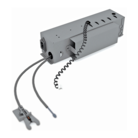
Elektro-weerstand - Résistance électrique - Elektro-Heizelement - Electric element
ANSCHLUSS ELEKTROHEIZELEMENT
Das Elektro-Heizelement vertikal in linken
oder rechten Anschluss unten montieren. Das
Gerät niemals ohne Wasserfüllung einschal-
ten.
In Anschluss auf die Oberseite des Kollektors
das mitgeliefertes Überdruckventil 3 bar mon-
tieren (siehe Seite 3-4).
ACHTUNG!
% Elektrisch: im anderen Anschluss
den Ablaßstopfen montieren. Den Radiator
mit der Hilfe von einem Trichter völlig mit
kaltem Wasser füllen. Das Ablaßwasser vom
Überdruckventil bei der ersten Totalauf-
wärmung mit einem Tuch auffangen!
Kombi: an der Oberseite entlüften. Den
Radiator nie zum Ausdehnungsgefäß hin
absperren. Der Rücklauf nie abschliessen.
Betriebsdrück: max. 3 Bar.
BESCHREIBUNG
1 Heizelement aus rostfreiem Stahl:
Hülse ø 1.5 cm
2 Anschluss 1/2”
3 Signallampe:
- Rot: Heizelement erwärmt auf maximal
Vermögen
- Grün/Rot flimmernd: Regulierungs-
leistung
- Grün: gewünschte Temperatur erreicht
- Signallampe aus: Radiator ausgeschaltet
4 Elektronisches Regelthermostat für
Wasserflüssigkeit (15-70 °C)
- Stand : Radiator ausgeschaltet
- Stand : Maxim. Heizung
- Frostschutz: den Thermostat in Stand
drehen. In Richtung des Uhrzeigers drehen
bis es “klickt” (Signallampe bleibt Grün).
5 Material: ABS Weiss
6 Elektronisches Steuerelement mit dop-
pelten Temperaturbegrenzer und perma-
nenter Kontrolle der elektrischen Isolation.
7 Anschlusskabel für Anschluss in
Abzweigdose mit Erdung: Länge: 1.2 m,
230 V mono - 50 Hz
CONNECTION ELECTRIC ELEMENT
Install the electric element vertically in the left
or right connection below. Never turn on the
radiator without filling it with water.
Insert the pressure release valve (3 bar) in
the top end connection (see page 3-4).
ATTENTION!
% Electrical: insert in the other connection
the drain plug. Fill the radiator completely with
cold water with the help of a siphon. Collect
the waste water of the pressure release valve
by means of a cloth when the apparatus is fully
heated for the first time.
Mixed: vent the radiator on the top end side.
Never isolate the radiator from the expansion
system, in other words never cut off the return
of the radiator. Working pressure: max. 3 bar.
DESCRIPTION
1 Element in stainless steel. Case ø 1.5 cm
2 Connection 1/2”
3 Indicator:
- red: the element has reached max. heating
- green/red indicating: regulation consump-
tion
- green: wanted capacity is reached
- indicator out: radiator switched off
4 Electronic thermostat on the fluid
(15-70 °C)
- Position : radiator switched off
- Position : maxim. heating
- Frost protection: turn the thermostat in
position. Turn clockwise until you hear
“click” (indicator stays green)
5 Material: ABS white
6 Electronic steering device with double tem-
perature limiter and permanent control of
the electronic insulation.
7 Connection cable for connection in socket
outlet with earthing: length: 1.2 m,
230 V mono - 50 Hz
AANSLUITING ELEKTROWEERSTAND
Monteer de elektro-weerstand vertikaal links
of rechts beneden. Zet de elektro-weerstand
nooit in werking zonder watervulling.
Plaats aan de bovenzijde van de radiator het
meegeleverde overdrukventiel 3 bar (zie pag.
3-4).
LET OP!
% Elektrisch: monteer de aftapstop in de
andere benedenaansluiting. Vul de radiator
volledig met koud water met behulp van een
trechter. Het spuiwater d.m.v. een doekje bij
de eerste opwarming opvangen!
Mixte: ontluchten aan de bovenzijde. Isoleer
de radiator nooit van het expansievat, m.a.w.
sluit de retour van de radiator nooit af.
Werkingsdruk: max. 3 bar.
BESCHRIJVING
1 Weerstand in roestvrij staal: huls ø 1.5 cm
2 Aansluiting 1/2”
3 Verklikkerlicht:
- rood: elektro-weerstand verwarmt op max.
vermogen
- groen/rood knipperend: regelings-
verbruik
- groen: gevraagde temperatuur is bereikt
- verklikkerlichtje uit: radiator is
uitgeschakeld
4 Elektronische regelthermostaat op de
watervloeistof (15-70 °C)
- Stand : radiator uitgeschakeld
- Stand : max. verwarming
- Vorstbeveiliging: draai de regelther-
mostaat op stand . Draai in uurwijzer-
zin tot u “klik” hoort (het verklikkerlicht
je wordt blijvend groen).
5 Materiaal: ABS wit
6 Elektronisch stuurelement met dubbele
temperatuurbegrenzer en permanente
controle van de elektrische isolatie.
7 Aansluitsnoer voor aansluiting in kontakt-
doos met aarding: lengte 1.2 m,
230 V mono - 50 Hz
RACCORDEMENT DE LA RÉSISTANCE
Monter la résistance électrique verticalement
dans le raccordement gauche ou droit en bas.
Ne jamais mettre la résistance électrique en
marche quand le radiateur n’est pas rempli
d’eau.
Fixez la soupape (3 bars) fournie dans l’ouver-
ture au-dessus du radiateur (voir page 3-4).
ATTENTION!
% Electrique: fixer le bouchon de vidange
dans l’autre ouverture en bas. Remplisser le
radiateur complètement avec de l’eau froide à
l’aide d’un entonnoir. Récolter l’ eau d’ écou-
lement du purgeur lors du premier réchauffage
maximal de l’appareil à l’aide d’un morceau
de tissu!
Mixte: purger au-dessus. Ne jamais séparer
le radiateur du réservoir de détente, c.à.d.
ne jamais fermer le retour du radiateur.
Pression de service: max. 3 bars.
DESCRIPTION
1 Résistance en acier inoxydable: gaine de
ø 1.5 cm
2 Raccordement 1/2”
3 Lampe témoin:
- rouge: la résist. chauffe à puissance max.
- vert/rouge clignotant: consommation de
régulation
- vert: température demandée atteinte
- lampe témoin éteinte: radiateur arrêté
4 Thermostat de réglage électronique sur le
liquide (15-70 °C)
- Position : radiateur arrêté
- Position : puissance maximale
- Protection antigel: tourner le thermostat
en position . Tourner dans le sens des
aiguilles d’une montre jusqu’au “clic” (la
lampe témoin reste au vert).
5 Matériel: ABS blanc.
6 Commande électronique avec double
limiteur de la température et contrôle per-
manent de l’isolation électrique.
7 Câble d’alimentation pour raccordement à
une boîte de dérivation avec terre:
longueur: 1.2 m, 220 V mono - 50 Hz.
60 cm
60 cm
60 cm
60 cm
B
A
WETTELIJKE BESCHERMZONE A
Een elektrische radiator met isolatieklasse
II mag in zone A geplaatst worden. De
aftakdoos moet achter de radiator worden
geplaatst. - In badkamers en keukens dient
de kontaktdoos (nooit een stopkontakt!)
op minimum 25 cm van de vloer te worden
geplaatst. De radiator mag nooit lager dan
de kontaktdoos worden geïnstalleerd. Er
dient een omnipolaire scheidingsschake-
laar met een openingsafstand van minstens
3mm te worden gebruikt. Het toestel dient
geplaatst en aangesloten te worden door
een erkend installateur volgens dit installat-
ievoorschrift, de nationale en de plaatselijk
geldende voorschriften.
VOLUME DE PROTECTION LÉGITIME A
Un radiateur électrique avec classe d’isola-
tion II peut être installé dans le volume A.
Dans ce cas, la boîte de dérivation doit être
placée derrière le radiateur. Dans les salles
de bains et les cuisines, il faut installer la
boîte de dérivation (jamais une prise de
courant) au minimum 25 cm du sol. Le radi-
ateur ne peut jamais être installé plus bas
que la boîte de dérivation. Il faut utiliser un
sectionneur multipolaire avec une distance
d’ouverture de min. 3 mm. L’appareil doit
être installé et raccordé par un installateur
agréé, conformément au présent mode
d’installation et aux règlements locaux et
nationaux en vigueur.
GESETZLICHE SCHUTZZONE A
Ein elektrischer Heizkörper mit Schutz-
klasse II darf in Zone A aufgestellt werden.
Die Kontaktdose soll hinter den Radiator
aufgestellt werden. In Badezimmer und
Küchen muss die Kontaktdose (nie ein
Steckkontakt) auf minimum 25 cm vom
Boden montiert werden. Der Radiator darf
nie tiefer als die Kontaktdose aufgehängt
werden. Einen omnipoligen Trennschalter
mit einer Öff nungsweite von mindestens
3 mm anwenden. Das Gerät muss von
einem anerkannten Installateur aufgestellt,
gemäss dieser Installationsvorschrift, sowie
auch der nationalen und örtlich geltenden
Vorschriften angeschlossen werden.
LEGAL PROTECTIVE ZONE A
An electrical radiator with insulation class
II may be installed in zone A. The socket
outlet must be placed behind the radiator.
In bathrooms and kitchens the socket outlet
(never a plug contact) has to be placed at a
minimum height of 25 cm above the fl oor.
The radiator may never be installed lower
than the adapter socket outlet. A fused
spare has to be used outside the room. The
appliance must be mounted and connected
by an acknowledge installer in accordance
with the installation instructions and nation-
al and currently applicable local regulations.
1
6.7 L
ø 1.5
6
6
7
2
3
4
5
150/50 600 watt: L = 35.5cm
180/60 1200 watt: L = 66.0cm
/ code: .
/ code: .
Klasse 
2.2
6
12.7
1.3
2.4
G 1/2"
G 1/2"
4.5
3.8
Mixte
Kombi
Mixed
T-stuk Geo
Té Geo
T-Stück Geo
T-piece Geo
/ code: .
/ code: .
Klasse 
 

.    JAGA N.V.



MIN 40 cm MAX 170 cm


This manual suits for next models

1

Other Jaga Heater manuals

Jaga BRIZA RAD 041 User manual

Jaga

Jaga BRIZA RAD 041 User manual

Jaga Helios User manual

Jaga

Jaga Helios User manual

Jaga Micro Canal User manual

Jaga

Jaga Micro Canal User manual

Jaga Vertiga User manual

Jaga

Jaga Vertiga User manual

Jaga Micro Canal User manual

Jaga

Jaga Micro Canal User manual

Jaga Eyecatchers Sani Panel User manual

Jaga

Jaga Eyecatchers Sani Panel User manual

Jaga OXYGEN Hybrid Campus User manual

Jaga

Jaga OXYGEN Hybrid Campus User manual

Jaga DBH-SET User manual

Jaga

Jaga DBH-SET User manual

Jaga Eyecatchers  Deco Space Vertical User manual

Jaga

Jaga Eyecatchers Deco Space Vertical User manual

Jaga BRIZA041 Wall User manual

Jaga

Jaga BRIZA041 Wall User manual

Jaga Eyecatchers Iguana Circo User manual

Jaga

Jaga Eyecatchers Iguana Circo User manual

Jaga MINI CANAL DBE User manual

Jaga

Jaga MINI CANAL DBE User manual

Jaga eCAB User manual

Jaga

Jaga eCAB User manual

Jaga STRADA User manual

Jaga

Jaga STRADA User manual

Jaga VERTIGA HYBRID User manual

Jaga

Jaga VERTIGA HYBRID User manual

Jaga Aurora H52-TYPE11 User manual

Jaga

Jaga Aurora H52-TYPE11 User manual

Jaga Maxi WT User manual

Jaga

Jaga Maxi WT User manual

Jaga BRIZA 038/052 User manual

Jaga

Jaga BRIZA 038/052 User manual

Jaga BRIZA 12 User manual

Jaga

Jaga BRIZA 12 User manual

Jaga BRIZA038 User manual

Jaga

Jaga BRIZA038 User manual

Jaga Eyecatchers Iguana Circo Plus_Wall User manual

Jaga

Jaga Eyecatchers Iguana Circo Plus_Wall User manual

Jaga Clima Quatro Canal H19 User manual

Jaga

Jaga Clima Quatro Canal H19 User manual

Jaga AVS User manual

Jaga

Jaga AVS User manual

Jaga Knockonwood User manual

Jaga

Jaga Knockonwood User manual

Popular Heater manuals by other brands

Sharndy ETW29 installation guide

Sharndy

Sharndy ETW29 installation guide

REMKO HTL 150 FB Operation,technology,spare parts

REMKO

REMKO HTL 150 FB Operation,technology,spare parts

ermaf GP 95 ACU operating instructions

ermaf

ermaf GP 95 ACU operating instructions

Holmes HFH136 owner's guide

Holmes

Holmes HFH136 owner's guide

Sentiotec Concept R combi Instructions for installation and use

Sentiotec

Sentiotec Concept R combi Instructions for installation and use

RenewAire RH Series Installation, operation and maintenance manual

RenewAire

RenewAire RH Series Installation, operation and maintenance manual

Sharper Image EV-HT05 Instruction manual and  warranty information

Sharper Image

Sharper Image EV-HT05 Instruction manual and warranty information

Skope 988E operating instructions

Skope

Skope 988E operating instructions

EQUATION HD15BDC Assembly, Use, Maintenance Manual

EQUATION

EQUATION HD15BDC Assembly, Use, Maintenance Manual

Supra Dalbeo Presence 1022 Installation and operating instructions

Supra

Supra Dalbeo Presence 1022 Installation and operating instructions

Holmes HFH421 owner's guide

Holmes

Holmes HFH421 owner's guide

Polar Electro Polar Heat C1 user manual

Polar Electro

Polar Electro Polar Heat C1 user manual

Toyotomi Zibro LC-32 operating manual

Toyotomi

Toyotomi Zibro LC-32 operating manual

SOMFY LIGHTING OUTDOOR RTS instructions

SOMFY

SOMFY LIGHTING OUTDOOR RTS instructions

BIEMMEDUE SE Series instruction manual

BIEMMEDUE

BIEMMEDUE SE Series instruction manual

AEG IR Comfort 1524 Operation and installation

AEG

AEG IR Comfort 1524 Operation and installation

Calix Slim Line 800 Assembly instructions

Calix

Calix Slim Line 800 Assembly instructions

Melchioni MAGMA user manual

Melchioni

Melchioni MAGMA user manual

manuals.online logo
manuals.online logoBrands
  • About & Mission
  • Contact us
  • Privacy Policy
  • Terms and Conditions

Copyright 2025 Manuals.Online. All Rights Reserved.