manuals.online logo
Brands
  1. Home
  2. •
  3. Brands
  4. •
  5. Jamara
  6. •
  7. Motorized Toy Car
  8. •
  9. Jamara Akron BL RTR 2,4 GHz User manual

Jamara Akron BL RTR 2,4 GHz User manual

Akron BL RTR 2,4 GHzNo. 05 3265 BL LiPo
30/15
ES - Instrucciones
GB - Instruction
ES - Información general
Jamara K. no se hace responsable de los daños causados al producto en sí o por medio de esto, a menos que esto
se debe al mal funcionamiento o errores de manejo. El cliente solo tiene la responsabilidad completa para el uso y
manejo adecuado, incluyendo, sin limitaciones, el montaje, el proceso de carga, el uso de hasta la elección de la zona
de aplicación. Por favor, consulte las instrucciones de uso y funcionamiento, contiene información y avisos importantes.
GB - General information
Jamara e.K. is not liable for any damage caused to the product itself or through this, provided this is due to improper
operation or handling errors. The Customer alone bears the full responsibility for the proper use and handling, including
without limitation, the assembly, the charging process, the use and choice of the operation area. Please refer to the
operating and user instructions, it contains important information and warnings.
ES - Declaración de conformidad
Por medio de la presente, la empresa Jamara e. K. declara que el modelo „Cocoon EP RTR 2,4 GHz, No. 053240,
No. 053241“ de conformidad con los requisitos esenciales y otras disposiciones pertinentes de la Directiva 1999/5/CE
y 2011/65/EU se encuentra.
Encontrará más información en: www.jamara-shop.com/Conformity
GB - Certicate of Conformity
JAMARA e.K. hereby declares that „Akron BL RTR 2,4 GHz, No. 053265“ follow the regulations and requirements as
well as any ther relivant directives of the EEC directive 1999/5/EC and 2011/65/EU.
Further information can also be found at: www.jamara-shop.com/Conformity
ES - Notas sobre el reciclado
Respete la normativa vigente sobre la eliminación de residuos, especialmente sobre baterías y pilas.
Lleve a reciclar las baterías solo si están descargadas
GB - Disposal restrictions
Please care for a environmental correct and legal way of disposing the batteries and/or accus. Please, only throw away
empty battery packs into the collect-boxes in your local shops or commune.
ES - ¡Este modelo no es ningún juguete!
¡No apropiado para menores de 14 años!
Achtung: Mantenga necesariamente lejos de los niños menores de 36 meses. RISK OF SUFFOCATION
Contiene piezas pequeñas.
GB - This model is not a toy!
Not suitable for people under 14 year.
Warning: Keep away necessarily children under 36 months. RISK OF SUFFOCATION!
Contains small parts which can be swallowed.
ES
¡Advertencia!
Accensione:
accendete prima il trasmettitore e poi il modellino.
Spegnimento:
spegnere prima il modellino e poi il trasmettitore
GB
Attention!
Before operating:
Switch the transmitter on rst then the model.
When nisished:
First switch off the model then the transmitter.
DE - Herramientas recomendadas | GB - Recommended Tool
No. 19 0065
Convergencia medidas
Camber adjusting Tool
No. 19 0060
Calibradores p. altura
Height lange
No. 23 2060
Cinta adhesiva 2 carasDoublesided
power tape
No. 23 2423
Adhesivo para  jacion de tornillos
Nut lock medium strength
No. 23 0409 20 g „Wheel blood“
Cola de neumatico
Rim Glue
No. 28 1904
Aceite de silicona p amortiguador
Shock-Oil Louise
No. 23 0461 400 ml
Espuma para limpiar especial
Special cleaning foam
No. 50 5401 pequeño/small
Clip de carroceria
Body clips
No. 15 3055
X-Peak 80 BAL
Cargador
Charger
No. 19 3130
Soporte de montaje deluxe
Car Stand rotatable
No. 19 7595
Herramientas 12in1
Tool 12in1
No. 15 3058
X-Peak 80 BAL Pult
Cargador
Charger
No. 19 7598
Atronillador trinquete 24en1
Ratchet screwdriver 24in1
No. 15 3060
X-Peak 50 BAL
Cargador
Charger
No. 05 9273 1:10
Clip de carroceria
Body clips
No. 28 1781 Louise
Hubs de perforación con las dimen-
sionesy la cubierta
Body reamer with cap and sizes
No. 15 3070
X-Peak BAL Touch USB
Cargador
Charger
2
ES - Primero Pasos
Se debe cerciorar que todas las partes del contenido de la caja estén inclui-
das. Transmisor, Carro, Cargador, paquete de la batería.
El paquete de la batería tiene que ser cargado antes de utilizarse. Conecte el
cargador en un enchufe 230V. Conecte el cargador a la batería. Si el enchufe
del cargador y la batería no coinciden, entonces usted encontrará un cable de
conexión en su caja. El tiempo de carga promedio de la batería v acía es de
alrededor de 6 - 8 horas (NiMh), 5 - 7 horas (LiPo).
Coloque 8 partes de baterías AA (doble a) en el transmisor. Si es batería re-
cargable, por favor cerciórese también de que esté completamente cargada.
Lea el capítulo para el uso del transmisor y sus controles cuidadosamente.
Apáguese el radio y cerciórese de todos los botones del transmisor están en
posición neutral. Ahora ponga la batería en la porta baterías en el vehículo.
Asegúrese de que el porta baterías está asegurado correctamente con los 2
seguros para el porta baterías incluidos. Ahora conecte la batería al control de
velocidad en el modelo. Mantenga el carro en el aire en caso de que el contro-
lador (ESC) del motor se encienda a su máxima potencia. Encienda el control
de la velocidad en el interruptor Encendido / Apagado (On /Off). Fije el modelo
en la tierra y compruébese su funcionamiento apropiado. Dirección derecha/
izquierda, acelerador/freno, hacia adelante y hacia atrás. Si las ruedas no
apuntan hacia adelante aún y cuando el volante de la transmisión está en
neutral, usted puede ajustarlo con el botón del ajuste la transmisión.
Trimm L/R = derecha/izquierda
Trimm V/R = adelante/atrás
Si las ruedas rotan hacia adelante o hacia atrás, aún y cuando no se les
haya indicado a través de la transmisión, entonces también el acelerador se
necesita ajustar en la transmisión. Le sugerimos que active ahora la unidad
receptora a Prueba de Fallas en el armado. Cuando se suministra, está
desactivado.
Se coloca la palanca del acelerador en posición neutral (véase el capítulo
A Prueba de Fallas). Se presiona el botón a prueba de fallas en el receptor
hasta que encienda/parpadee y se suelta para activarlo. Compruebe este
principio en un vehículo eléctrico solamente con el acelerador en po-
sición neutral, ya que de otro modo el modelo regresa a la posición
previamente programada del acelerador teniendo una pérdida de la se-
ñal del transmisor.
Ahora usted puede hacer la primera prueba de conducción. Si éste es su
primer carro rc, le recomendamos conducirlo en una pequeña pista de prueba
para familiarizarse con el control del vehículo y los controles del transmisor.
¡Atencion!
Su vehículo tiene un pivote de suspensión delantera. Esto tiene numerosas
ventajas. Es muy resistente y es de fácil mantenimiento. La conguración (set-
up) del carro ha sido diseñada para que el eje motriz no se proyecte hacia
afuera. Como con cualquier modelo, los tornillos y los pernos se pueden per-
der durante una interrupción del carro. Esto puede resultar en una tolerancia
del eje motriz. El eje motriz puede entonces proyectarse hacia afuera si se
ejerciera presión alta. El tornillo interno de la bola (No. del artículo.: 505081)
le permitirá ajustar la tolerancia dando por resultado los ajustes nos del ancho
de la rodada. Para mejores resultados al colocar la bola del pivote por primera
vez, por favor ajuste siempre el pivote superior y más bajo de la misma forma.
Apriete tanto como el pivote lo permita y que se pueda levantar y bajar fácil-
mente pero no tanto que lo proyecte fuera si usted le da un ángulo completo
a la dirección. El tornillo del enchufe de plástico (No. del artículo.: 505080) se
utiliza solamente para asegurar el nudillo de la dirección. Éste no debe ser
demasiado apretado, de lo contario la dirección no queda suave y su manejo
puede ser afectado negativamente.
GB - Getting Started
Make sure that all parts from the box content are included. Transmitter, Car,
Charger, battery pack.
The battery pack has to be charged before use. Plug the charger into a 230V
outlet. Connect the charger to the battery. If the plug of the charger and battery
do not match, then you will nd a connection lead in your box. The average
charging time of the empty battery is about 6-8 hours (NiMh), 5 - 7 hours
(LiPo).
Place 8 pieces of AAbatteries into the transmitter. If rechargebale, please also
make sure these are fully charged.
Read the chapter for usage of the transmitter and its controls carefully.
Turn the radio off and make sure all the trim buttons on the transmitter are in
neutral position. You have purchased a RTR model, which means it should
be ready for immediate use after charging all batteries. You need to check
the car, electronics and all plastic parts after each use to make sure no parts
are damaged. Also all the moving parts must be checked for their clearance,
bolts and screws that they are tight. Now put the battery into the battery holder
in the vehicle. Make sure that the battery holder is secured properly with the
2 included clips for the battery holder. Now connect the battery to the speed
control in the model. Keep the car in the air in case that the motor turns at full
power. Switch the speed control on the On / Off switch. Set the model on the
ground and test it for proper functioning. Steering right/ left, throttle/ brake,
forward and backward. If the wheels do not point straight forward even though
the steering wheel on the transmitter is in neutral, you can adjust it with the
trim button on the transmitter.
Trim L/R = steering
Trim V/R = forward/backward
Should the wheels rotate forward or backward, even though no command
was given through the transmitter, then also the throttle needs to be trimmed
on the transmitter.
We encourage you now to activate your receiver‘s built-in Failsafe unit. On eli-
very it is turned off. Leave the throttle lever in neutral position (see chapter
Fail Safe). Press the fail-safe button on the receiver until it ashes and let go
to activate. Check this principle in an electric vehicle only in the neutral
position of the throttle, because otherwise the model goes into the pre-
viously programmed throttle position in a loss of the transmitter signal.
Now you can make the rst test drive. If this is your rst rc car, we recommend
to drive it on a small test track to familiarise yourself with the control of the
vehicle and the controls of the transmitter.
Attention!
Your vehicle has a pivot front suspension. This has a number of advantages.
It is very robust and easy to maintain. The set-up of the car has been done so
the drive shaft will not pop out. As with any model, screws and bolts can losen
during break-in of the car. This can result in tolerance of the drive shaft. The
drive shaft can then pop out if high pressure is applied. The inner ball screw
(item No.: 505081) will enable you to adjust the tolerance resulting in ne
adjustments of the track width. For best results when setting up the pivot ball
for the rst time, please always adjust the upper and lower pivot in the same
way. Fasten as far as the pivot can still be pulled up and down easyly but not
as far that it will pop out if you give full steering angle. The outer plastic socket
screw (item No.: 505080) is only used for securing of the steering knuckle.
This should not be too tight, otherwise the steering is not smooth and the
handling can be adversely affected.
ON/OFF
L/R V/R
Trim
50 5080
50 5081
07 9996
50 5079
Cargador/Charger
Batería/Battery
ESC
ON/OFF
Batería/Battery
ESC/Conector de la Bateria.
ESC/Battery connector
¡Importante!
Con el uso de las baterías de Li-Po, el apagado de baja tensión del cont-
rolador para activar Consulte el manual del controlador. De lo contrario,
la batería LiPo puede ser dañado por una descarga total.
Important!
By using LiPo batteries take care that the undervoltage shutdown is acti-
vated. Otherwise, your LiPo battery can be damaged by deep discharge.
ES - Emisora CCX Car 2,4 GHz | GB - Transmitter CCX Car 2,4 GHz
ES - Operación de control
Vista lateral
1. Programación remota
2. Antena de 2,4 GHz
3. Volante
4. Pedal Pulso
5. Compartimiento de las
baterías
GB - Controls
Side View
1. Programming Box
2. 2,4 GHz Antenna
3. Steering Wheel
4. Throttle Lever
5. Battery Hatch
Campo de programación
6. Invertir la dirección
7. Encendido / aleación
8. Trim de la Dirección
9. Enciende y apaga
A. Inversa de gas
B. Compruebe la alimentación
C. Botón de encendido
D. Dual Rate
E. Gas
Programming Panel
6. Steering Reverse
7. Power LED
8. Steering Trim
9. ON/OFF Switch
A. Throttle Reverse
B. Power Check
C. Binding Button
D. Dual-Rate
E. Throttle Trim
En el teclado de la emisora se permite programar el CCX 2.4 Car de manera fácil y rápida. Los dos canales pueden
direccionar con facilidad a la derecha o a la izquierda con el sistema en los anuncios indicadores.Com el indicar del
cargamento avisa lo cuánto se ha cargado la estación.
Thanks to the logical and well thought out lay-out of the Programming Panel and the positioning of the switches and
LEDs the CCX 2.4 Car transmitter can be quickly and simply programmed. Both channels can be trimmed and the
direction changed. Furthermore the transmitter is equipped with a Dual Rate system and a red LED indicates the
state of the battery charge.
1
2
3
4
5
6
7
8
9
A
B
C
D
E
La parte posterior
F. Canal de recarga
G. Canal que desee introducir el
cable simulador.
Si se carga en la toma de carga,
por favor, abra la tapa del com-
partimento de la batería. Esto se
utiliza para el enfriamiento.
Rear Side
F. Charge Socket
G. Simulator Cable Socket
If charging the batteries via the
charging socket, the battery
hatch cover should be removed
to ensure sufcient cooling. G F
2,4 GHz
Antena
Antenna
Receptor/Receiver
061171
Brenda la antena de 2.4 GHz perpendicular, como en la
fotografía en el lado. Mas no debe mantenerlo en la parte
metálica, debido a de extensión.
Mount the 2.4 GHz antenna vertically as shown in the dia-
gram. Do not allow any metal object to come into contact
with the antenna or to shield it as this will reduce the range.
3
Technische Daten:
Max. Belastung 60 A
Kurzzeit Belastung 380 A
Innenwiderstand 0,0007 Ohm
Einsatzbereich RC-Cars 1:10
Akkus 4 - 9 NiCd- / NiMH-Zellen
2 - 3 LiPo-Zellen
BEC-Spannung 6,0 V
BEC-Belastung 1,5 A
Motor-Typen sensorlose BL-Motoren
Schutzeinrichtung Übertemperaturschutz/Unterspan-
nungsabschaltung/Eingangsimpul-
skontrolle
Größe ~ 31,5 x 27,5 x 24 mm (mit Lüfter)
Gewicht ~ 32 g (ohne Anschlusskabel)
Programmierbar 11 Programmierschritte (Bremse,
Unterspannung, Startmodus etc.)
Technical data:
Max. Current 60 A
Burst Current 380 A
Internal Resistance 0,0007 Ohm
For Use With Cars or Trucks scale 1:10
Battery packs 4 - 9 NiCd- / NiMH cells
2 - 3 LiPo cells
BEC Voltage 6,0 V
BEC Current 1,5 A
Motor Types Sensorless Brushless motors
Protective Circuits Temperature cut-off/Low voltage
cut-off/input signal
Size 31,5 x 27,5 x 24 mm (with fan)
Weight 32 g (without cable)
Programmable 11 Programming steps (Break,
Low Voltage, Start Mode etc.)
ES - El uso del controlador
Conexión al receptor, batería y motor
Conecte el regulador, el receptor, la batería, el servo de dirección y el motor
según el diagrama. Tenga especial cuidado con la polaridad correcta de la ba-
tería. Conecte el cable rojo con el polo positivo ’+’ y el cable negro con el polo
negativo ’-’ de la batería. Hay que juntar los conectores ’#A’, ’#B’ y ’#C’ con los
conectores del motor. La tecla ’SET’ sirve para la programación. Conecte la
salida del receptor “Canal 2“ con el cable correspondiente al regulador. Tenga
en cuenta la asignación de los canales de su emisora. Conecte la salida del
regulador con los conectores del motor. No existe un orden determinado para
ello. Una vez que lo tiene todo conectado, compruebe su correcto funcio-
namiento. Si el motor girará en dirección contraria, cambie dos conectores
cualquiera del mismo.
Atención:
Ud. puede cambiar la dirección de giro del motor con la función “Reverse“ en
su emisora, aunque tendrá que tener en cuenta que después hay que calibrar
de nuevo al regulador.
Using Your ESC
Connecting the Receiver, Battery Pack and Motor
Connect the ESC, the receiver, the battery pack, the steering servo and the
motor together following the diagram below.
Ensure that you observe the correct polarity of the battery pack. The red cable
should be connected to the ‘+‘ Plus Pole and the black cable to the ‘-‘ Minus
Pole. The ’#A’, ’#B’ and ’#C’ plugs are connected to the motor. The ‘SET‘
button initiate the programming mode.
The ESC should be plugged into the throttle channel of your receiver which
is normally channel 2. If in doubt, check your Radio- Control System’s inst-
ructions. The 3 Motor wires can now be connected, these connectors can be
plugged in any order, and if the motor rotates in the wrong direction any 2 of
the wires should be swapped.
Note:
You can use the servo reverse function of your transmitter to reverse the motor
direction but the ESC will have to be re-calibrated afterwards.
ES - Controlador (instalada) | GB - Controller (installed)
Motor
#A, #B, #C
ESC
channel 2
Switch
Receiver
Steering servo
Plus pole
red cable
Minus pole
black cable
ES - Para encender el transmisor y el receptor
En la moderna emisora de 2.4 GHz es necesario que el emisor y el receptor
estén conectados por el módulo. La emisora sólo aceptará la señal su estación.
Si por alguna razón usted tiene que repetir la nueva conexión, haga los sigu-
ientes pasos:
A. Coloque la batería cargada en la emisora o pilas nuevas. Deje la emisora
desenchufada.
B. Coloque el cable de conexión de los tres canales.
C. Encender la emisora, mientras haces el bindingde la batería con el receptor.
Depende de la versión del software, señala su receptor varios modo de
binding (en vez de parpadear, la LED brilla o esta apagado). El binding es
siempre lo mismo en todas las versiones. La LED en el receptor impieza a
parpadear y indica que el receptor no esta en el modo binding.
D. Pulse el botón de encendido de la estación y, al mismo tiempo cambiar el
canal.
E. La emisora impieza a parpadear y indica que estas en el modo binding.
F. Quitar el dedo el botón de encendido de la emisora y retirar del enchufe del
receptor.
G. Quitar el dedo el botón de encendido de la emisora y retirar del enchufe del
receptor.
H. Cuando haga la instalación, tratar de hacer todo correctamente.
I. Si no hay éxito en el procedimiento, vuelva hacerlo todo otra vez.
La siguiente ilustración representa grácamente el proceso de las unidades, la
identicación y la articulación de los elementos individuales que deben ser op-
erados.
GB - Binding the receiber to the transmitter
As with all modern 2.4GHz R/C systems the receiver must be bound to the trans-
mitter to ensure that the receiver will only react to signals from that transmitter.
If you wish to re-bind the receiver with the transmitter please proceed as follows:
A. Ensure that the transmitter is tted with fresh or fully charged batteries and
leave the transmitter off.
B. Plug the binding plug (included) into the channel 3 socket on the receiver.
C. Switch the receiver system on by connecting the battery or turn in a BEC
operating on a controller to control. Depending on your software version
of your receiver indicates the different binding mode (instead of
ashing lights for example LED or remains out completely). The binding
process as such is in all versions. The receiver LED will begin to ash
indicating that the receiver is in bonding mode.
D. Press and hold down the binding button on the transmitter whilst switching it
on.
E. The transmitter will begin to ash indicating that the receiver is in bonding
mode.
F. Release the binding button on the transmitter and disconnect the receiver
from the battery or turn off the controller. Release the binding plug from the
receiver.
G. Switch of the transmitter. And remove the binding wire. The system be bound
at the next start .
H. Install all properly and check anything very precisely.
I. If the receiver fails to bond or does not function after bonding repeat the
above procedure until a successful bonding is achieved.
The diagram illustrate the bonding process and show the locations of the relevant
components.
Enchufe de unión
Binding Plug
Fail Safe
Setup LED
Cómo instalar la función a prueba de fallas
1. Instrucciones de la función
La función de la protección de pérdida de control es principalmente para los barcos y carros r/c y los res-
guarda de algún daño a través del canal del acelerador. Cuando el receptor está fuera de la señal de control,
el receptor del acelerador volverá a regresar automáticamente a la posición inicial que se instaló antes de
comenzar para evitar la acción de error:
2. Cómo establecer la función
a. Encienda la energía del transmisor y entre a la condición de trabajo
b. Conecte el receptor a la energía y entre a la condición de trabajo, la luz de la señal en receptor estará
parpadeando en todo momento.
c. Controle el acelerador del transmisor y mantenga el servo o el controlador ESC en posición neutral.
d. Presione el botón de ajuste, el LED va a parpadear por 3 segundos (Véase en la gura de la izquierda).
e. Suelte el botón de ajuste. Termina el ajuste.
3. Prueba
a. Encienda el transmisor y entre a la condición de trabajo.
b. Haga contacto del receptor con la energía e inicie la condición de trabajo
c. Apague la energía del transmisor.
d. El acelerador del servo se instalará automáticamente.
e. Al terminar con los pasos arriba mencionados signicará que la instalación esta correcta.
How to setup the fail safe function
1. The instruction of function
The function of protection of losing control is mainly for r/c boats and cars and keeps them away from damage
through throttle channel. When the receiver is out of control signal, the receiver of throttle will automatically
return to the initial position which set up before starting to avoid the error action :
2. How to set the function
a. Switch on the transmitter power and enter into the working condition
b. Connect the receiver with power and enter into the working condition, the signal light on receiver will blink
all the time.
c. Control the throttle of transmitter and keeps the servo or ESC in the neutral position.
d. Press the setting button, the LED will be ash for 3 seconds (see on pict. left).
e. Release the setting button. The setting is nished.
3. Testing
a. Switch on the transmitter and enter the working condition.
b. Contact the receiver with power and enter the working condition.
c. Turn off the power of transmitter.
d. The throttle of servo will be set automatically.
e. Finish these steps above means the setting is ok.
4
Congurar la distancia de frenado y de aceleración
Para un funcionamiento óptimo, es necesario calibrar el regulador.
Para esto hay que  jar las 3 posiciones, hacia delante, hacia
detrás y punto muerto. Existen tres razones que justi quen la
necesidad de una calibración.
• Antes del primer uso
• Si usamos una nueva / otra emisora
• Después de una reprogramación del punto muerto y/o de los recorridos
de servo en la emisora
Para la calibración, siga los siguientes pasos :
1. Encienda la emisora con el receptor apagado. Si usa un equipo Futaba,
tenga en cuenta que la función del gas tiene que estar en “Reverse“. Los
recorridos máximos de servo tienen que estar en punto neutral. Además
tiene que haber apagado una posible función de ABS en su emisora.
2. Después encienda el receptor con la tecla del regulador. Al mismo tiempo
mantenga presionado la tecla ’SET’. Así entrará en el modo calibración,
el LED empezará a parpadear. Cuando ocurra esto, suelte la tecla. Si no
suelta la tecla ’SET’ nada mas que comienza a parpadear el LED, entrará
en el modo programación. Si esto no era su intención, tiene que volver a
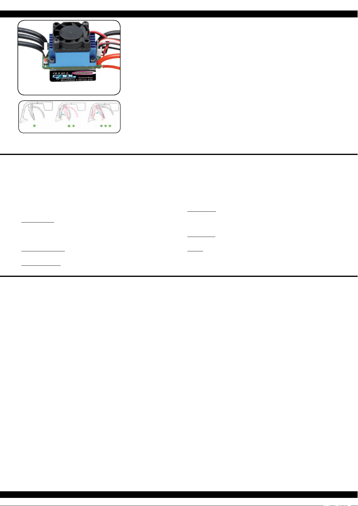
apagar el regulador. La siguiente ilustración enseña como entrar en el
modo calibración.
3. Se pueden con gurar tres parámetros :
• Posición neutral
• Recorrido máximo hacia delante
• Recorrido máximo hacia atrás
En las siguientes ilustraciones puede ver estos procesos de forma
gráca.
4. Mueva el mando del acelerador a posición neutral y presione la tecla
’SET’, el LED verde parpadea una vez y el motor emite una señal
acústica. Mueva el mando del acelerador a la posición  nal para ir hacia
delante y presione la tecla ’SET’, el LED verde parpadea dos veces y el
motor emite dos señales acústicas. Mueva el mando del acelerador a
la posición  nal para ir hacia atrás y presione la tecla ’SET’, el LED
verde parpadea tres veces y el motor emite tres señales acústicas.
Tres segundos después de acabar la calibración ya puede arrancar el
motor.
Calibrating the Throttle/Brake
To ensure that your ESC operates correctly it has to be calibrated. During
this process the full throttle, stop and brake positions will be set. There are 3
occasions when the unit must be calibrated.
• Before using the ESC for the rst time
• If you change to a new transmitter
• If the neutral point or servo throw is changed within your transmitter
To calibrate the system, please proceed as follows:
1. Ensure that the receiver is switched OFF and switch ON the transmitter. If
you are using a Futaba transmitter, please ensure that you have reversed
the throttle function. The throw should be set to neutral. If the transmitter
is tted with an ABS function this must be de-activated.
2. Press and hold down the ‘SET‘ button on the ESC and switch the receiver
switch ON. This will switch the ESC into Calibration’ mode and the LED
will begin to blink. If you fail to release the ‘SET’ button as soon as the
LED blinks, the ESC will enter ‘Programming’ mode. If this happens, you
will have to switch the ESC off and start again to enter ‘Calibration’ mode.
3. 3 Parameters can be set here:
• Neutral point
• Full throttle forwards
• Full throttle reverse
The procedure for setting these 3 points is outlined below:
4. Ensure that the throttle control is in the neutral position and press the
‘Set‘ button. The green LED will ash once and the motor will omit a
beep. Move the throttle control to the full throttle (forwards) position and
press the green ‘Set‘ button. The green LED will ash twice and the motor
will omit 2 bleeps. Move the throttle control to the full reverse position and
press the ‘Set‘ button. The green LED will ash 3 times and the motor will
omit 3 bleeps. 3 Seconds after this procedure has been followed, the
motor is ready for use.
Señales y dispositivos de seguridad
Durante el modo de funcionamiento normal, las señales de los LEDs signi can lo siguiente :
a. Mientras que el mando del acelerador se encuentra en posición neutral, no se enciende ni el LED verde, ni el LED
rojo.
b. Se enciende el LED rojo, cuando el vehículo se mueve hacia delante o hacia atrás. Cuando frena, el LED rojo
parpadea de forma acelerada.
c. Se enciende el LED verde, cuando el mando del acelerador se encuentra en la posición máxima hacia delante o
hacia atrás
A través de señales de advertencia, el regulador informa de ciertos estados:
1. Al encender, el procesador comprueba el voltaje que entra, y si éste estuviera fuera de los límites aceptables, suena
una señal acústica doble con una pausa de un segundo, entre las señales individuales “beep-beep-, beep-beep-,
beep-beep-”
2. Si la señal de entrada no es correcta, suena una señal acústica con una pausa de dos segundos, entre las señales
individuales “beep-, beep-, beep-”. Este regulador está equipado con una serie de sistemas de protección para
asegurar su uso de forma segura:
1. Corte por baja tensión:
En el momento que el voltaje de la batería Lipo baje durante 2 segundos por debajo del límite programado, se
apagará el motor. Tenga en cuenta, que no se puede volver a arrancar el motor, mientras que el voltaje siga por
debajo de 3,5 V por célula.
Baterías NiCd y NiMH con un voltaje de entre 9,0 V y 12,0 V serán tratadas como baterías Lipo de tres células,
baterías con menos de 9,0 V serán tratadas como baterías Lipo de dos células. P.ej. Si una batería NiMH tiene un
voltaje de 8,0 V y el límite esta jado en 2,6 V por célula Lipo, el apagado sucederá con 5,2 V (2 x 2,6 V). De este
modo también se protegen las baterías NiCd y NiMH de forma efectiva de daños por baja tensión.
2. Corte por sobre calentamiento
En el momento que la temperatura del regulador sube por encima de 95°C durante 5 segundos, se apagará el motor.
Después del apagado es imprescindible dejar enfriar el regulador, ya que en caso contrario sufre daños. ¡No se
puede desactivar esta función bajo ningún concepto!
3. Señal de entrada incorrecta
Si la señal de entrada es considerada incorrecta durante 0,2 segundos, se apagará el motor.
LED’s, errors and protection
In normal use the LED will illuminate as follows:
a. If the throttle control is in the neutral position, neither the red or green LED will illuminate.
b. The red LED will illuminate if the vehicle is driving forwards or in reverse. If the vehicle is braking, the red LED will
ash rapidly.
c. The green LED will illuminate when the vehicle is at full throttle either forwards or in reverse.
In certain circumstances the ESC will omit an acoustic tone to warn you of a problem:
1. On switching on, the ESC will check the battery pack voltage and if it falls outside the correct values it will omit
double signals followed by a 1 second pause: “beep-beep-, beep-beep-, beep-beep-”
2. If the ESC does not receive a signal from the transmitter it will omit single signal followed by a 2 second pause:
“beep-, beep-, beep-”
The ESC has ben equipped with a series of protective circuits to ensure safe operation:
1. Low voltage cut-off:
If the voltage drops below the set value for more than 2 seconds the ESC will switch the motor off. Please note that
the motor cannot be started again if the voltage is below the choosen value per cell.
If a NiCd or NiMH pack with a voltage of between 9 and 12 Volts is connected, the ESC will treat is as if it was a 3 cell
LiPo pack. If the pack voltage is below 9.0 Volts, the ESC will react as if it was a 2 cell LiPo pack. For example, if a
NiMH pack is connected with a nominal voltage of 8 Volts and the cut-off value is set to 2.6 Volts per cell, the ESC
will switch the motor off at 5.2 Volts (2 X 2.6 V). This will protect the NiMH packs from ‘deep discharge’.
2. Temperature cut-off
If the internal temperature of the ESC rises above 95°C for more than 5 seconds the motor will switch off. After the
ESC switches off it has to cool down before operating again. Otherwise the ESC will be damaged. This function
should not be disabled!
3. Signal loss
If the signal is lost for more than 0.2 seconds the ESC will switch the motor off.
Botón SET cuando se cambia
Press SET button while switching on
ES - Problemas y sus posibles soluciones
Aunque este regulador para modelos de coche y camión
RC está sometido a exhaustivos controles de calidad,
puede ocurrir algún problema alguna vez. En la sigui-
ente tabla puede ver posibles problemas, sus razones
y la posible solución.
Después de encender, el motor no arranca y no se
oye ninguna señal acústica.
1. La batería o la conexión de batería es incorrecta.
- Compruebe los cables, conectores y la batería en
si.
Después de encender, el motor no arranca y se oye
una señal acústica doble cada segundo.
1. El voltaje que le entra al regulador es incorrecto, o
demasiado alto o demasiado bajo.
- Compruebe el voltaje de la batería.
Después de encender, el motor no arranca y se oye
una señal acústica cada 2 segundos.
1. La señal de entrada es considerada incorrecta.
- Compruebe la emisora y el receptor y también el
cable de conexión entre receptor y regulador.
El motor gira en dirección contraria.
1. Las conexiónes del motor han sido cambiadas.
- Cambie dos cables de conexión entre motor y
regulador.
El motor se para de forma repentina.
1. La señal de entrada no es correcta.
- Compruebe emisora, receptor y cables de servo.
2. El voltaje de la batería es demasiado bajo.
- Cargue su batería.
El motor funciona de forma irregular, va a tirones.
1. Existe alguna conexión suelta.
- Compruebe todas las conexiones con mucho
detalle.
2. La transmisión de radio sufre graves interferencias
intermitentes.
- Apague el regulador y vuelva a encenderlo. Si
todavía no consigue un funcionamiento correcto,
use su vehículo en otro sitio
GB - Troubleshooting
Although this ESC has been subjected to the most strin-
gent quality control it is possible that you may experience
a problem during operation. In this case please use the
table below to assist in fault nding.
The motor will not rotate after switching on.
No signal is present.
1. The battery pack or battery pack connectors are
faulty.
- Check all of the connectors and the battery pack.
The motor will not turn after switching on. The ESC
omits double signals with a 1 second interval.
1. The input voltage is too high or too low.
- Check the battery pack voltage.
The motor will not turn after switching on. The ESC
omits single signals with a 2 second interval.
1. No or a poor receiver signal.
- Check both the transmitter and receiver as well as
the ESC connecting cable.
The motor turns in the wrong direction.
1. The motor connecting cables are swapped
- Swap 2 of the ESC/motor connecting cables
The motor suddenly stops turning.
1. The battery voltage is too low.
- Charge the battery pack.
2. No signal.
- Check the transmitter, receiver and all of the cables
Only steering response
The motor stutters or runs irregularly.
1. One of the connectors is loose.
- Carefully check all of the connectors.
2. The receiver has intermediate interference.
- Switch the system off and then on. If the interfe-
rence persists, operate the model in another
location.
5
Nota Importante:
Además de las señales visuales del LED rojo, el motor genera las señales acústicas correspondientes. Después de
cada programación es necesario apagar el regulador, ya que se activa la nueva conguración al volver a encender-
lo. Tenga en cuenta, que a partir de la quinta fase de programación, las señales cambian ligeramente. Aqui un un
destello largo simboliza el paso 5, seguido por otras señales cortas para los próximos pasos.
Adjunto un ejemplo :
Destello largo + señal corta = Fase de programación 6
Destello largo + dos señales cortas = Fase de programación 7
Destello largo + tres señales cortas = Fase de programación 8, y así sucesivamente.
Important note:
In addition to the red LED blinking, the motor will omit an acoustic signal. After every change to the values the ESC
must be switched off to store the values. The new settings will not be effective until the ESC is re-started. Please
note that program option 5 and above (Professional settings) are slightly different in that they will be indicated by a
long blink rst followed by short blinks.
For example:
Long blink + one short = Program option 6
Long blink + two short = Program option 7
Long blink + three short = Program option 8, etc.
ES - Estructura del menú del regulador GB - Menu structure
Encender emisora
Switch transmitter ON
Todos los demás pasos de programación funcionan de la misma manera.
All of the other menu options are accessed in the same manner.
rojo | red LED parpadea | blinks 1 x ► 0 %
rojo | red LED parpadea | blinks 2 x ► 5 %
rojo | red LED parpadea | blinks 3 x ► 10 %
rojo | red LED parpadea | blinks 4 x ► 15 %
rojo | red LED parpadea | blinks 5 x ► 20 %
rojo | red LED parpadea | blinks 6 x ► 25 %
rojo | red LED parpadea | blinks 7 x ► 30 %
rojo | red LED parpadea | blinks 8 x ► 40 %
El LED rojo parpadea una vez, signica ir hacia delante con freno.
Red LED blinks once indicating forwards and brake.
El LED rojo parpadea dos veces, signica ir hacia delante y hacia atrás con freno.
The red LED blinks twice indicating forwards, reverse and brake.
rojo | red LED parpadea | blinks 1 x ► OFF
rojo | red LED parpadea | blinks 2 x ► 2,6 V
rojo | red LED parpadea | blinks 3 x ► 2,8 V
rojo | red LED parpadea | blinks 4 x ► 3 V
rojo | red LED parpadea | blinks 5 x ► 3,2 V
rojo | red LED parpadea | blinks 6 x ► 3,4 V
Por favor, presione cada vez la tecla ’SET’ para cambiar el valor ac-
tual, el LED rojo indica el valor actual, parpadear una vez signica 1,
parpadear dos veces signica 2 y así sucesivamente.
Press the ‘SET‘ button to select the desired value. The red LED will
indicate which value is selected. 1 X blink indicates value 1, 2 x blinks
indicate value 2 etc.
Encender regulador presionando
al tiempo la tecla ’SET’
Press and hold the ‘SET‘ button
down and switch the receiver on
El LED rojo parpadea
The red LED blinks
El LED verde parpadea una vez
The green LED blinks once
El LED verde parpadea dos veces
The green LED blinks twice
El LED verde parpadea tres veces
The green LED blinks 3 times
El LED verde parpadea X veces
The green LED blinks X times
Presionar tecla
durante 3 segundos
Press the button
for 3 seconds
Presionar tecla
durante 3 segundos
Press the button
for 3 seconds
Presionar tecla
durante 3 segundos
Press the button
for 3 seconds
Soltar tecla
Release button
Soltar tecla
Release button
Soltar tecla
Release button
Soltar tecla
Release button
Presionar tecla
Press button
Presionar tecla
Press button
Presionar tecla
Press button
Presionar tecla
Press button
Fase de programación 1,
Modo de conducción
Program option 1, Drive mode
Fase de programación 2, Modo de freno
Program option 2, Brake mode
Fase de programación 3, Baja tensión
Program option 3, Low voltage cut-off
Fase de programación X
Program Option
Las celdas grises muestran la conguración predeterminada.
* Usted nunca debe elegir un momento demasiado alto. El motor y El regulador puede ser dañado. A temperaturas por
encima 80 ° C en el motor, el momento debe ser reducida o la Traducción ajustado (abreviado)
The elds which are shaded in grey indicate the factory settings.
* You should never choose a too high timing. The engine and the controller can be damaged. For temperatures above
80 ° C on the engine, the timing must be reduced or the transmission adjusted (shortened).
ES - Programación del regulador GB - Programming the ESC
Fase de programación
Program Mode
Valores de programación
Program Value
1 2 3 4 5 6 7 8
Conguración básica
Default Setting
1. Modo de conducción
Drive Mode
Hacia delante, con freno
Forwards, brake on
Hacia delante/marcha atrás,
con freno
forwards / reverse, brake on
2. Freno
Drag Brake Force
0 % 5 % 10 % 15 % 20 % 25 % 30 % 40 %
3. Baja Tensión
Low Voltage OFF 2,6 V/célula
2,6 V/cell
2,8 V/célula
2,8 V/cell
3,0 V/célula
3,0 V/cell
3,2 V/célula
3,2 V/cell
3,4 V/célula
3,4 V/cell
4. Modo Arranque
Start Mode
suave
soft
normal
normal
agresivo
aggressive
muy agresivo
very aggressive
Conguración profesional
Professional Settings
5. Fuerza de frenado maximo
Brake Max.
25% 50% 75% 100%
6. Máximo marcha atrás
Max. Reverse
25% 50% 75% 100%
7. Fuerza de frenado mínima.
Brake Force Min.
= freno fuerza
= As Brake max.
0 % 20% 40%
8. Zona punto muerto
Neutral Zone
6% estrecho
6% Narrow
9% normal
9% normal
12% ancho
12% Wide
9. *Timing
*Timing
0,00° 3,75° 7,50° 11,25° 15,00° 18,75° 22,50° 26,25°
10.Tipo de motor
Motor Type
BL-Motor
Brushless
11. Sobrecalentamiento
Temp. Cut-Off
95°C sin protección
Off
6
ES
Este regulador está equipado con amplias opciones de conguración. Para alcanzar su meta de una programación
óptima de forma rápida y segura, siga la estructura de menú ilustrada y la tabla de arriba sobre las diferentes posibili-
dades de programación. Los diferentes pasos de programación de la tabla signican lo siguiente:
1. Modo de conducción:
En el modo “carrera“ – valor 1 – el vehículo solamente conduce hacia delante, el freno se encuentra activado,
conducir marcha atrás no es posible. Este modo es especialmente adecuado para el uso del vehículo en
competición. En el modo de conducción – valor 2 – (hacia delante/marcha atrás con freno) el vehículo también
puede ir marcha atrás, con el freno activado. Este modo es adecuado para usos normales y para
entrenamientos.
Nota Importante:
En el modo de conducción 2, se inicia la marcha atrás con un movimiento doble. Cuando saca el mando del
acelerador de la zona “hacia delante“ a la zona “marcha atrás“, el motor se frena. Durante este proceso, el
vehículo no llega a pararse del todo. Si ahora vuelve a llevar el mando del acelerador a la zona “marcha atrás“,
el vehículo irá marcha atrás, parando primero por muy poco tiempo. Si después vuelve a empujar el mando del
acelerador hacia delante, da igual si el motor está en modo frenar o modo marcha atrás, el vehículo avanzará
hacia delante.
2. Freno:
Este menú indica el efecto del freno en porcentajes. El rango de ajuste se encuentra desde 0 hasta un 40%..
3. Baja Tensión:
En este paso se congura el límite de corte. El rango de ajuste se encuentra entre 3,4 V y 2,6 V por célula. Si se
pasa por debajo de este límite, el regulador corta el motor.
4. Modo Arranque:
Esta opción le permite congurar el arranque de su vehículo. Puede elegir entre cuatro posibilidades, desde un
comienzo suave a uno muy agresivo. Tenga en cuenta que para los modos mas rápidos, es decir, agresivo o
muy agresivo, se precisan baterías muy potentes con poca resistencia interna, ya que en caso contrario se
pueden sufrir caídas de voltaje y el motor vacilará al arrancar. Además es muy importante ajustar el motor y la
transmisión acorde con el modo de arranque elegido
5. Fuerza de frenado máxima.:
El regulador está equipado con un freno proporcional a la posición del mando del acelerador. El efecto máximo
del freno se consigue al empujar el mando del acelerador hacia delante al máximo. Un efecto de freno fuerte,
consigue parar el vehículo en muy poco tiempo, pero por otra parte también implica un alto grado de desgaste
en componentes mecánicos como p.ej. la transmisión.
6. Máximo marcha atrás:
En este paso de programación puede congurar la velocidad máxima en
marcha atrás.
7. Fuerza de frenado mínima:
En este paso de programación se puede congurar la fuerza del freno en
la fase inicial de la frenada. En la conguración predeterminada, el valor
es igual al valor del freno en general (ver punto 2).
8. Punto muerto:
En este paso de programación puede con gurar la zona del punto
muerto. Existen tres posibilidades, estrecho, normal y ancho. Las dos
siguientes ilustraciones explican el proceso y muestran las diferentes
zonas para emisoras de palancas y emisoras de volante.
9. Timing:
Para motores sin escobillas (“brushless“) es importante congurar el
Timing correctamente. Este regulador se puede ajustar de forma óptima.
Rogamos tenga en cuenta las indicaciones del fabricante del motor.
Como norma general consta que cuanto mayor sea el Timing
seleccionado, mayor es la potencia de salida del motor, con un consumo
de corriente aumentado de forma signi cativa.
10. Tipo de motor:
El regulador está diseñado exclusivamente para el uso con motores sin
escobillas (“brushless“). No existen otras opciones de programación en
este paso.
11. Sobrecalentamiento:
El regulador está equipado con una protección muy efectiva contra el
sobrecalentamiento. El motor se apaga si se pasa el límite de 95°C
durante un tiempo de 5 segundos.Esta condición se indica con un LED
verde que parpadea. No se debe desactivar esta función bajo ningún
concepto.
Para evitar la programación con la tecla “Setup“, también existe la posibilidad de
programar el regulador de forma muy cómoda con una tarjeta de programación
(Ref. 08 1453) que se vende por separado.
GB
This ESC is tted with many useful functions and to help you to be able to make the most of the various options they
are explained below. Please use the programming table shown on page 6 together with these explanations to program
your ESC quickly and effectively:
1. Drive mode:
If option 1 is selected in Drive mode, the vehicle will only drive forwards and the brake is active which make this
mode the best choice for racing. In mode 2 the vehicle can be driven forwards or in reverse and the brake is also
active. This mode is useful for general use and training.
Note:
When option 2 is selected, moving the throttle control back past the neutral point will initially activate the brake. If
the throttle control is then moved back to the neutral position briey the ESC will switch over to reverse. Moving
the ESC forwards will make the vehicle drive forwards regardless of whether it was braking or moving in reverse.
2. Drag Brake force:
In this option the drag braking force can be set. The value is set as a percentage and the values are from 0 to
40%
3. Low voltage:
In this option you can set the low voltage cut-off value. The cut-off voltage can be set between 3.4 and 2.6 Volts
per cell. Once the cut-off voltage has been reached the motor will stop.
4. Start Mode:
With this option you can choose how the vehicle will accelerate when full throttle is applied and you can set the
value between ‘Soft‘ and ‘Very Aggressive‘. Please note that if you select one of the 2 ‘Aggressive’ modes that
you will need to have batteries with a very low internal resistance otherwise the voltage will drop due to the high
current draw and the motor may stutter. Also ensure that your motor and gearing are capable of carrying the high
loads.
5. Brake Max.:
The ESC is equipped with a braking system which works proportionally to the throttle control. This means that
the further the throttle control is moved rearwards the more braking force will be applied. A higher value here will
mean that the vehicle will brake harder but more strain will be placed on the components, for example, the
gearing.
6. Max. Reverse:
This option is used to adjust the top speed when driving in reverse
7. Brake Force Min.:
The effect that the brake has when rst applied can be set here. The default
setting will be whatever
8. Neutral Zone:
The ‘neutral Zone’, which is the area between forwards and reverse or braking
can be set to ‘Narrow’, ‘Normal’ or ‘Wide’ as shown in the illustration below.
This Zone can be set for both ‘stick’ or ‘pistol-grip’ type transmitters as shown.
9. Timing:
It is important that the correct timing is selected for a Brushless motor and you
can set the timing here. Please refer to you motor’s instructions for the correct
setting. As a rule of thumb, raising the timing will increase the output of your
motor but at the cost of a higher current draw end heat developing
10. Motor Type:
This ESC has been exclusively designed for use with Brushless motors and
so you cannot make any changes here.
11. Temp. Cut-Off:
The ESC is equipped with an accurate temperature sensor which will switch
the unit off if a temperature of 95°C is exceeded for 5 seconds or more. This
situation will be indicated by a ashing green LED. This function should not
be
disabled.
To avoid the programming procedere with the set up botton, you can all so use the
seperatly available Programmcard (Ord.No. 08 1453).
El modelo no responde
1. La batería o las baterías están vacías o defectuosas
- Cargue la bateria o sustituyala
2. Motor defectuosas
- Sustituya el motor
3. Cable Flojo o dañado
- Reconecte el cable o sustituya
4. El transmisor esta apagado o la conexion esta dañada
- Sustituya el transmisor o enciendalo
5. Receptor defectuoso
- Sustituya el receptor
6. El regulador de velocidad esta defectuoso
- Conecte apropiadamente o sustituya
El modelo reacciona sin ser controlado
1. El transmisor esta apagado o la conexion esta dañada
- Sustituya el transmisor o enciendalo
2. El control no esta calibrado o programado
correctamente
- Recalibrar o reprogramar.
3. Receptor defectuoso
- Sustituya el receptor.
El motor comienza a correr al momento de encender,
sin movimiento alguno.
1. Se instaló el Mecanismo de Seguridad de forma incor-
recta
- Programar el Mecanismo de Seguridad en neutral
2. El acelerador ajustado al transmisor no está en neutral
- Poner el acelerador ajustado en neutral
El modelo solo se mueve hacia adelante.
1. El control no esta calibrado o programado
correctamente
- Recalibrar o reprogramar.
Solamente Responde el volante
1. El control o regulador no esta calibrado o esta
defectuoso
- Calibrar el reguladror o sustituirlo
El volante no responde.
1. El sistema de la dirección está defectuoso
- Sustituya el servo
2. El doble-tipo en el transmisor está instalado muy abajo
- Incrementar el doble tipo del transmisor.
3. La palanca del volante esta muy sucia
- Limpiar y lubricar bien
Fuerte ruido de la traccion.
1. Engranaje principal, daños en el piñón o en el
diferencial
- Partes dañadas deben de ser sustituidas
2. La red de engranaje no está correcta
- Re-ensamble red de engranaje
El regulador de velocidad se apaga al manejar.
1. Bajo voltaje de la bateria.
- Cargar la bateria.
2. Sobrecalentamiento
- Dejar que el regulador se enfrie.
Los ejes de transmision se caen
1. Ancho de la pista demasiado grande
- Reducción del ancho de la pista.
Model does not respond
1. Battery or batteries empty or defective
- Charge battery or replace
2. Motor broken
- Replace motor
3. Loose or damaged cable
- Reconnect cable or replace
4. Transmitter turned off, lost or damaged binding
- Transmitter back on, bind or replace
5. Defective receiver
- Replace receiver
6. Speed controller is defective or connection issue
- Connect properly or replace
Model react uncontrolled
1. Transmitter turned off, lost or damaged binding
- Transmitter back on, bind or replace
2. Controller not calibrated or programmed incorrectly
- Recalibrate or reprogram
3. Defective receiver
- Replace receiver
Engine is running when you turn on inadvertently
1. Incorrectly set Failsafe
- Failsafe program to neutral
2. Throttle trim on the transmitter is not in neutral
- Throttle trim set to neutral
Model moves forward only
1. Controller not calibrated or programmed incorrectly
- Recalibrate or reprogram
Only steering response
1. Regulator or Motor is defective or not Calibrated
- Calibrate speed controller or replace motor
Steering does not respond
1. Power steering defect
- Replace servo
2. Dual Rate on the transmitter set too low or to 0
- Dual rate increase
3. Very dirty steering lever or steering knuckle
- Clean and lubricate well
Loud noise from the drive
1. Main gear, pinion or differential damage
- Do not continue! affected part needs to be replaced
2. Incorrect gear mesh
- Reset gear mesh
Speed controller shuts off while driving
1. Low voltage cut-off, battery voltage too low
- Charging the battery
2. Overtemperature
- Let speed controller cool
Front drive shafts fall out
1. Too large track width
- Track width reduction
ES - Solución de Problemas | GB - Troubleshooting
max. adelante
Max. forwards
Zona para
seguir adelante
Forwards zone
zona neutral
Neutral zone
zona neutral| Neutral zone
punto neutro
Neutral point
punto neutro | Neutral point
Zona para los frenos y marcha atrás
Brake and reverse zone
Zona para los frenos y marcha atrás
Brake and reverse zone
max. la fuerza de frenado
Max. Braking effect
max. la fuerza de frenado
Max. Braking effect
max.
adelante
Max.
forwards
Zona para seguir adelante
Forwards zone
7
LED
Normas de seguridad
• Asegúrese de que el contacto de carga con la humedad y la exposición a la luz solar directa.
• Cuando deje de utilizar, desenchufe la fuente de alimentación y las baterías.
• No coloque el cargador o las pilas en las zonas in amables y los procedimientos de
seguimiento, no deje desatendida.
• Evite cualquier corto circuito y comprobe la polaridad de las dos potencias, la de entrada y la
batería conectada.
• No cargar el cargador defectuosas o dañadas.
• No cargar las baterías defectuosas o dañadas.
• Respetar a la indicación del fabricante de la batería.
Safety Information
• Never expose the charger to moisture or direct sun light.
• Never leave the charger unattended when in use, and always operate it on a re proof surface.
• Avoid short circuits at all costs. Always observe the correct polarity.
• Batteries should always be allowed to cool down before you charge or discharge them.
• Never try to charge/discharge damaged charger.
• Never try to charge/discharge damaged packs or cells.
• Follow the directions given by the battery manufacturer.
Manual de instrucciones del cargador
1. Conecte el cable (de salida) de la fuente de alimentación de a la toma de entrade del bloque de
carga (portapilas). Los LEDs rojo y verde se encenderán, indicando que está listo para cargar.
El LED rojo indica que la alimentación funciona, el LED verde muestra que hay voltaje de
salida.
2. Conecte la batería LiPo con su cable de equilibrado (3 hilos) a salida del bloque de charga. El
brillo del LED verde cambriará dependiendo del nivel de carga actual. Cuando brille al máximo
(muy claro) la batería estará cargada. Una carga completa tarda unos 2 a 3 horas dependiendo
de la capacidad de la batería. Si al conectar la batería el LED no se oscurece, la batería estará
totalmente cargade.
Tiempo de carga
El tiempo de carga depende la la capacidad de la batería.
Ejemplo:
Corriente de carga = 0,8A/h
Capacidad de la batería = 800 mAh
Tiempo de carga = 1 hora (h)
Operating Instructions Carger
1. Connect the charger to the AC Network and plug it into a grounding receptacle. The LED on the
charger will indicate it is ready for charging.
2. Connect the charger (B) to the battery pack (A). The LED will change the color to show it is
charging. If the battery pack is completely empty, a full charge process will take approx.
2 ~ 7 hours, depending on the batteries capacity. Once the LED changin the color again, charge
has been completed.
Charging Time
The charging time varies depending on the capacity of the battery.
Example:
Charge current = 0.8 A/h
Battery Capacity = 800 mAh
Charging time = 1 hour (h)
Atención:
Cargar sólo baterías adecuadas con este cargador. Baterías adecuadas son de litio polímero con
máx. 2 células, máx. 7,4 V de tensión y máx. 5000mAh. La batería debe tener un conector de ba-
lanceador tipo JST-XH. La carga de las baterías no adecuadas pueden causar daños en el cargador
y en la batería. Riesgo de incendio! El conector del balanceador de cargador no se puede soldar
o cambiar algo.
Caution:
Only charge suitable battery‘s with this charger. Suitable battery‘s are lithium polymer battery‘s with
max. 2 cells, max. 7.4 V nominal voltage and max. 5000mAh. The battery must have a balancer
plug type JST-XH. The charging of unsuitable battery‘s can cause damage to the charger and the
battery‘s. Fire Hazard! The balancer plug of the charger is not allowed to get altered or soldered to
a different balancer plug type!
Montaje del diferencial delantero
Front gear assembly diagram
50 5078
50 5075
50 5073
50 5071
50 5074
50 5072
50
5085
50 5076
07 9989
No. 50 5155
Dif. delante+atras comp.
Differencial complete
No. 50 5155
Dif. delante+atras comp.
Differencial complete
Montaje del diferencial trasero
Rear gear assembly diagram
50 5078
50 5075
50 5074
50 5073
50 5024
50 5145
50 5023
50 5024
50 5076
50 5071
50 5085
07 9989
07 9996
07 0806
8
Montaje del suspensión del delantera
Steering assembly diagram
50 5080
50 5081
50 5079
50 5100
07 9989
50 5099
07 9996
50 5028
Antes de cada uso, asegúrese de revisar todas las cone-
xiones de tornillos y cable. Su vehículo cuenta con un
pivote frontal de suspensión esto tiene muchas ventajas.
Es muy resistente y de fácil mantenimiento. El sistema del
carro ha sido fabricado para que el eje del manejo no se
salga. Como en cualquier otro modelo, tuercas y tornillos
pueden extraviarse al rodar el carro. Lo anterior puede re-
sultar con cierta tolerancia en el eje de manejo. El eje de
manejo puede salirse si se aplica demasiada presión. La
tuerca interior de bola (artículo núm. 505081) le permite
ajustar la tolerancia roduciendo nos ajustes en el ancho
de la pista. Para mejores resultados al instalar el pivote
de bola por primera vez, siempre ajuste el pivote superior
e inferior de la misma manera. Atornillado. Tanto como se
pueda el pivote todavía puede moverse fácilmente hacia
arriba y abajo pero no tanto como para salirse si es que
desea virar al máximo en ángulo. La tuerca plástica de
enchufe exterior (artículo núm. 505080) se usa sólo para
asegurar el nudillo de la dirección. Este no debe estar muy
apretado, de lo contrario el volante no estará suave y el
manejo puede afectarse de forma adversa.
Before each use make sure to check all bolt connections
and cable connections. Your vehicle has a pivot front sus-
pension. This has a number of advantages. It is very ro-
bust and easy to maintain. The set-up of the car has been
done so the drive shaft will not pop out. As with any model,
screws and bolts can losen during break-in of the car. This
can result in tolerance of the drive shaft. The drive shaft
can then pop out if high pressure is applied. The inner ball
screw (item No.: 505081) will enable you to adjust the to-
lerance resulting in ne adjustments of the track width. For
best results when setting up the pivot ball for the rst time,
please always adjust the upper and lower pivot in the same
way. Fasten as far as the pivot can still be pulled up and
down easyly but not as far that it will pop out if you give full
steering angle. The outer plastic socket screw (item No.:
505080) is only used for securing of the steering knuckle.
This should not be too tight, otherwise the steering is not
smooth and the handling can be adversely affected.
50 5054
50 5097
50 5087
50 5054
07 9989 50 5082
07 9996
50 5028
Montaje del suspensión trasera
Rear shaft assembly
9
Montaje del amortiguadores
Shock assembly
50 5064
Montaje del servo set
Buffer assembly
50 5029
10
Montaje de radio placa
Buffer assembly
03 3215
07 9841
50 5093
50 5027
Montaje del soporte del motor
Motor assembly
50 5126 (22 Z./T.)
50 5026
08 1460
11
ES - Inclinación - Positivo/Negativo
delante y atras
A Negativo:
En el terreno es mejor, porque los
bordes de las ruedas se levantan
en la curva. Esto permite una mayor
velocidad en la curva.
Se recomienda aprox. 1,5 grados
negativo delante y 0 grados atras
como un valor medio. Un alto
ángulo de inclinación negativo,
puede peorar la propiedades de
marcha.
B Positivo:
Con una inclinación positiva se
deberia evitar, porque el vehículo
tiene una peor porpiedades de
marcha.
GB - Negative camber / positive camber
front and rear
A Negative camber:
Better grip on terrain, as the edge of
the wheels stem into the ground
allowing higher cornering speed.
We recommend approx. imately 1.5
degrees negative front and an ave
rage of 0 degree to the rear. An
excessive negative camber angle
can deteriorate the ride quality.
B Positive camber:
A Positive camber should be
avoided in your vehicle due to
poorer ride quality.
ES - El ajuste del tren de aterrizaje
Los consiguientes ajustes son posible:
Convergencia negativa / positiva
AConvergencia negativa: La dirección es menos directa y
el vehículo tiende a sobrevirar.
BConvergencia positiva: La dirección es directa y el
vehículo tiende a subviraje.
Dirección directa no está precisa.
GB - Suspension Settings
The following settings are possible:
toe-in / toe-out
AToe-in: The responsiveness of the steering is less direct
and the vehicle tends to oversteer, but
it has better directional stability.
BToe-out: More direct steering response and understeer,
but has a worse directional stability.
A
A
BB
mejor
rm mejor
rm
menos
soft
Camino muelle
Shock angle
Suspensión muelle
Spring tension
menos
soft
Tornillo
Tornillo primavera = menos viajes
Desenrosque = más viajes
Viajar
Spring travel
Turnbuckle
turn shorter = Toe-out
turn more = Toe-in Rear camber
Inclinación atras
B
A
ES - Suspensión muelle duro/mórbido delante y atras
Duro: Un comportamiento más directo de la suspensión.
Mórbido: Un comportamiento menos directo de la
suspensión.
GB - Front caster high / low
Less caster: Less caster has a worse directional stability, but
provides a better steering on corner entries.
High caster: A higher caster has a better directional stability,
but can result in worse corner turn-in.
ES - Suspensión muelle duro/mórbido
delante y atras
Duro:
Un comportamiento más directo de la
suspensión.
Mórbido:
Un comportamiento menos directo de la
suspensión.
Ángulo de amortiguador
mórbido/tenso
delante y atras
Mórbido:
Dirección directa
Tenso:
Menos dirección directa
Camino muelle - mejor/menos
delante y atras
Menos:
Menos altura sobre el suelo y una bajo
centro de gravedad del vehículo.
Mejor:
Major altura sobre el suelo y major
centro de gravedad del vehículo.
GB - Spring tension hard / soft front
and rear
Harder:
More direct response of the suspension
but reduced grip.
Softer:
Less direct response of the chassis but
more grip.
Damper angle soft / rm
front and rear
Soft:
More direct steering
Firming:
Less direct steering
Spring defelxion more / less front
and rear
Less:
Less ground clearance and lower center
of gravity
More:
More ground clearance and higher
center of gravity
Ángelo de inclinación
Caster angle Clip
montado delante =
inclinación mayor
montado atras =
inclinación bajo
Clip
front mounted =
higher caster
rear mounted =
lower caster
mejor
rm
menos
soft
A
A
BB
B
A
Camino muelle
Shock angle
Suspensión muelle
Spring tension
12
ES - Puntos de ajustes | GB - Setting points
Suspensión muelle
(pinza menos o más)
Suspensión muelle
(pinza menos o más) Spring tension
(less or more clip)
Camino muelle
atrás / arriba
Camino muelle Shock angle
Inclinación atras
Inclinación delante
Track front
Inclinación Caster
Spring tension
(less or more clip)
Shock angle
rear / top
Rear camber
Suspensión muelle
Spring tension
Camino muelle
Shock angle
Camino muelle
Shock angle
Camino muelle
Shock angle
Inclinación
(sólo tornillo interior)
Camber
(only inner screw)
13
ES - Lista de repuestos | GB - Spare parts
No. 50 5088
Parachoques A
Damper plate A
No. 05 2860
Neumatico + Llante
Wheels
No. 50 5191
Soporte carroceria
Shock tower
No. 50 5064
Amortiguador
Shock set
No. 50 5089
Parachoques B
Damper plate B
No. 50 5145 65 Z./T.
Engrenage principal
Middifferential gear set
No. 08 1460
CR B3650 3450KV 3S4P
Motor eléctrico 3,17 mm eje
E-Motor w. 3,17mm shaft
No. 50 5099
Brazo superior/delantero
Front upper suspension set
No. 50 5040
Suporte brazo
Suspension xed mount set
No. 50 5090
Eje delantero / trasero
Wheel axle
No. 50 5027
Bandeja radio
Radio tray set
No. 50 5096
Barra de acoplamiento
Steering rod connecting set
No. 50 5100
Brazo inferior/delantero
Front lower suspension set
No. 50 5085
Rueda dendada A
Diff. bevel gear set A
No. 50 5091
Àrboles de transmisión
Drive shaft
No. 50 5093
Splasher rueda dentada
principal
Connect mount set
No. 50 5097
Direccional
Rear upper pulling rod set
No. 50 5087
Brazo inferior/trasero
Rear lower suspension set
No. 50 5071
Rueda dendada B
Diff. bevel gear set B
No. 50 5155
Dif. delante+atras comp.
Differencial complete
No. 50 5072
Arbol de pinoneria
Main gear
No. 50 5073
Steel bevel gear
Bever gear
No. 50 5074
Caja diferencial
Differential case set
No. 50 5075
Caja pinoneria
Gear box
Suspensión muelle
Spring tension
Camino muelle
Shock angle
Camino muelle
Shock angle
Camino muelle
Shock angle
Camino muelle
Shock angle
14
ES - Lista de repuestos | GB - Spare parts
No. 50 5076
Rotula
Connecting cup
No. 50 5084
Medir rueda
Hex joint set
No. 50 5081
Tornillo cabeza rotonda
Ball head screw
No. 50 5026
Soporte del motor
Motor mount set
No. 50 5077
Servo de ahorro clip
Buffer steel colum
No. 50 5078
Portada de transmisión
delantera / trase
Shock mount
No.50 5082
Mangueta de zitel trasero
Rear shaft hub
No. 50 5029
Servo Set
Steering saver
No. 50 5028
Manguito de la dirección
Suspension arm shaft
No. 50 5079
Muñón del eje
Steering hub set
No. 50 5023
Pinion unidad central
Gear mount set
No. 50 5030
Cardano
Central shaft
No. 50 5054
Manguito de la dirección
Suspension arm shaft
No. 50 5080
Engranaje
Ball head nut
No. 50 5024
Arbol de pinoneria
Rear main gear
No. 50 5101
Chasis
Chassis
No. 50 5032
Soporte de la batería
Battery case
No. 07 9996 Ø5*Ø11*4
Cojinetes
Ball bearing
No. 50 5052 M3*15
Tornillo
Round head selftapping
cross screw
No. 50 5056 M2*8
Tornillo
Flat head selftapping cross
screw
No. 50 5060 M3*3
Esparrago roscado alle
Set screw
No. 50 5126 3,17mm
Piñón 22Z. 48DP
Motor gear 22T. 48DP
No. 07 0806 Ø5*Ø10*4
Cojinetes
Ball bearing
No. 26 6400 M3*8
Tornillo
Flat head machine cross
screw
No. 50 5057 M3*12
Tornillo
Umbrella head machine
cross screw
No. 50 5061 M2*11
Pin
Pin
No. 08 1458 60A
CR B60S
Regulador Speed Brushless
Speedcontroller Brushless
No. 50 5048 M3*10
Tornillo
Round head selftapping
cross screw
No. 50 5053 M3*6
Tornillo
Flat head machine cross
screw
No. 50 5058 M3*8
Tornillo
Umbrella head machine
cross screw
No. 50 5062 M2*10
Pin
Pin
No. 50 5021
Servo conducíon
Servo pulling rod set
No. 50 5049 M3*12
Tornillo
Round head selftapping
cross screw
No. 50 5055 M3*10
Tornillo
Flat head selftapping cross
screw
No. 50 5059 M3*10
Esparrago roscado allen
Set screw
No. 14 1390
7,4V 5000mAh 2N 30C
Batería LiPo-Racing
Battery LiPo-Racing
No. 50 5045 Ø 7 mm
E-clip
No. 50 5046 Ø 4 mm
E-clip
No. 17 7444 M4
Tuerca autoblocante
Nylon Nut
No. 50 5045 Ø 2,5 mm
E-clip
No. 07 9989 Ø 10*Ø15*4
Cojinetes
Ball bearing
No. 50 5063 Ø 4*Ø8*0.5
Guarnicíon
Shim
No. 05 9274
Clip de carroceria
Body clip
No. 50 5188
Carroceria
Body
No. 50 5189
Adhesivi
Decals
No. 03 7194
Cargador 230 V
Charger 230 V
No. 50 5190
Soporte Spoiler
Wing stay
No. 50 5195
Spoiler
Wing
15
ES - Accessorios Tuning | GB - tuning parts
ES - Lista de repuestos | GB - Spare parts
No. 50 5182
Wheelybar
Wheelybar
No. 50 5285
Receptor Box
Receiver Box
No. 50 3581 M4
Tuerca con borde #
autoblocantes
Wheel nuts, self-locking
No. 50 5094 1:10
Ruedas + llantas
Wheels+Rims
No. 50 5116 1:10
Ruedas + llantas, camino
Wheels+Rims, Street
No. 50 5148
Tapa p. engranaje Lexan
Gear covering, Lexan
No. 13 0155
Aletas para motor
Cooling ns
No. 07 9880 Futaba
Palanca de control Alu.corto
Control arm Alu short
Futaba
No. 50 5163
Cardan, delante / detrás
Joint front / rear
No. 07 4416
High End 9712 MG
Servo
Servo
No. 06 1200
CCX 2,4 Pro
Emisora
Transmitter
No. 13 0156
Radiador d motor alu. aktiv
c. ltro
Cooling ns active with fan
No. 13 0157
Radiador mot. alu.aktiv
vario ltro
Cooling ns alu active
variable with fan
No. 06 1220
Compa 2,4 GHz
Emisora
Transmitter
No. 50 5287
Proteccion golpes LED
Bumper LED
No. 50 3690 1:10
Spoiler Alu Vario Twin
Rear Spoiler Alu Vario Twin
No. 50 5546
Amortiguador
Shocks front/rear
No. 07 4430 AQUA7 MG
Servo
Servo
No. 50 5548
Engrenage principal
Main gear
Información del product | Product information
1/2” OFFSET 4WD anterior &posterior
1/2” OFFSET 4WD rear & front
assemble para | assemble for:
● Jamara Tiger, Lipon, Akron, Cocoon, Toxic,
Splinter anterior & posterior | rear & front
● Nitro JATO 2WD posterior | rear
● Nitro STAMPEDE 2WD posterior | rear
● Nitro RUSTLER 2WD posterior | rear
● Electric STAMPEDE 2WD anterior | front
● Electric RUSTLER 2WD anterior | front
● Electric STAMPEDE 4WD
anterior & posterior | rear & front
● Electric MONSTER JAM 2WD posterior | rear
En las ruedas MT se tiene que observar el diámetro. Según el
coche pueden ser necesarios cambiosen la carrocería o en la
dirección o bien la ampliación del ancho de vía.
Regarding the MT wheels please pay attention to the wheel
diameter. Depending on your car, modifications to the body
and the steering or rather a wheel spacer can be necessary.
1/10 Truck (Monstertruck/Stadiontruck)
65 mm 50 mm 50 mm65 mm
Neumáticos pegados a la
llanta
Tyres glued on rims
„MT Pioneer“ Ø 120 mm
No. 05 2854 12 mm 1/2OS
Neumáticos pegados a la
llanta
Tyres glued on rims
„MT Uphill“ Ø 120 mm
No. 05 2860 12 mm 1/2OS
Reifen verklebt auf Felge
Tyres glued on rims
„ST Uphill“ Ø 100 mm
No. 05 2872 12 mm 1/2OS
Neumáticos pegados a la
llantae
Tyres glued on rims
„MT Rocket“ Ø 115 mm
No. 05 2851 12 mm 1/2OS
Neumáticos pegados a la
llantae
Tyres glued on rims
„ST Rocket“ Ø 100 mm
No. 05 2863 12 mm 1/2OS
Neumáticos pegados a la
llanta
Tyres glued on rims
„ST Hummer“ Ø 100 mm
No. 05 2866 12 mm 1/2OS
Neumáticos pegados a la
llanta
Tyres glued on rims
„MT Spider“ Ø 115 mm
No. 05 2857 12 mm 1/2OS
Neumáticos pegados a la
llanta
Tyres glued on rims
„ST Jumbo“ Ø 100 mm
No. 05 2869 12 mm 1/2OS
65 mm (MT)
50 mm (ST)
65 mm (MT)
50 mm (ST)
Salvo error o modicación técnica. Copyright JAMARA e. K. 2015
Prohibida su reproducción o distribución, por cualquier medio, salvo consentimiento expreso de JAMARA e. K.
All rights reserved. Copyright JAMARA e.K. 2015
Copying or reproduction in whole or part, only with the expressed permission of JAMARA e.K.
JAMARA e.K.
Inh. Manuel Natterer
Am Lauerbühl 5 - DE-88317 Aichstetten
Tel. +49 (0) 75 65/94 12-0 - Fax +49 (0) 75 65/94 12-23
[email protected] ●www.jamara.com
Service - Tel. +49 (0) 75 65/94 12-66
kundenservice@ jamara.com
ES - Luces de señalización LED Car para la conexión con el receptor | GB - Car LED signal lights for connection to the receiver
14
7 8
25
36
9 1410
22 mm
22 mm
105 x 26 x 21 mm 105 x 26 x 21 mm
108 x 18 x 24 mm
105 x 26 x 21 mm
96 mm
108 x 18 x 24 mm
108 x 18 x 24 mm
11 12
96 mm 96 mm 13 92 mm
*
1 No. 50 5500 azul | blue , Ø 16 mm
Función | Function: intermit | ashing 4 SMD LED‘s
2 No. 50 5501 amarillo | yellow, Ø 16 mm
Función | Function: intermit | ashing 4 SMD LED‘s
3 No. 50 5502 rojo/azul | red/blue
Función | Function: intermit | ashing 16 SMD LED‘s
4 No. 50 5503 azul/azul | blue/blue
Función | Function: intermit | ashing 16 SMD LED‘s
5 No. 50 5504 amarillo/amarillo | yellow/yellow
Función | Function: intermit | ashing 16 SMD LED‘s
6 No. 50 5505 azul/azul | blue/blue
Función | Function: intermit | ashing 16 SMD LED‘s
7 No. 50 5506 amarillo/amarillo | yellow/yellow
Función | Function: intermit | ashing 16 SMD LED‘s
8 No. 50 5507 rojo/azul | red/blue
Función | Function: intermit | ashing 16 SMD LED‘s
* De señaldirigible a través de 3 Canal de la emisora.
Signal adjustable by 3rd channel on your transmitter.
9 LED Proyector | Spotlight
No. 50 5284 Ø 19 mm
Montaje Izquierdo & Derecho. Por ejemplo para parachoque y bastidor
de tubo. Función: Luz permanente 4 LEDs
Finalizar con cable de conexión
Left & Right pin-through mounting e.g. for impact protection & tube frame.
Function: Continuous light 4 LEDs
Done with connection cable.
Car LED Signallicht 4-fach Alu | Car LED Signal Light (4) Alu
• para la conexión con el receptor • 4 SMD LED‘s
• Diverso efectos de iluminacíon/Luz permanente ajustable mediante botón
• for connection to the receiver • 4 SMD LED‘s
• Various lighting effects/continuous light adjus table by button
10 No. 50 5510 Ø 21 mm, blanco | white
11 No. 50 5511 Ø 21 mm, amarillo | yellow
12 No. 50 5512 Ø 21 mm, rojo/azul | red/blue
13 No. 50 5513 17 mm, blanco | white
14 LED Badge
No. 70 2500
Highlights:
• Extra brillante 576 direccionable individual, controlado por
microprocesador, LED‘S
• Esta inclusa una software, con esto se pueden programar liberamente
varios textos y efectos
• 576 Extra bright single micro processor controlled LEDs.
• Different text and effects programmable by included Software.
Funciones | Functions:
• Hasta 8 textos y efectos diferentes opcional sucesivamente o por
separado jugable
• 3 diferentes niveles de luminosidad
• Efectos: Escritura ( todas las direcciones), parpadeo, animación
• 8 different text, respectively effects, playable after another or single.
• Brightness adjustable in 3 steps
• Effects: Ticker (all directions), blinker, animation
Ejemplo de uso | Box Contents:
• Placa con el nombre • Placa de puerta • Regalo publicitario • Instrucciones
• Badge • Data/charging cable • Software • Instructions
Ejemplo de uso | Example of use:
• Placa con el nombre • Placa de puerta • Regalo publicitario • Partygag
• Name badge • Door sign • Advertising • Party joke
Medidas | Dimensions: 94 x 30 mm
94 mm
30 mm
ES - Seguridad
• Lea atentamente las instrucciones y la seguridad antes de poner el modelo en funcionamiento!
• Este dispositivo no debe ser utilizado por personas (incluidos niños) con discapacidad física,habilidades sensoriales
o mentales o la falta de experiencia y / o conocimientos, porque son responsables de su propia seguridad persona de
supervisión o instrucción sobre cómo se utiliza el dispositivo. O la persona que son supervisados o instruidos en
cómo usar.
• El usuario es responsable en su totalidad para el correcto uso del modelo.
• Se prohíbe cualquier modicación de la estructura del modelo ya que anulará la garantía inmediatamente.
• No deje nunca el modelo, el motor o las baterías expuestos a los rayos solares de manera directa, colóquelos a la
sombra.
• Prestar atención de que algunas partes del modelo pueden calentarse.
• Si el modelo, el motor o la batería se mojan, es necesario limpiar todo acuradamente en el seco y limpio.
Betrieb
• Mantenga el modelo lejos de los niños, por lo que el modelo no es adecuado (ver nota en edad).
• No haga funcionar su modelo en las proximidades de las es taciones de radio,líneas eléctricas, cajas de
transformadores, o como! Esto signi ca que puede la interferencia de radio principal causa la pérda de control sobre
el modelo!
• Evitar de conducir el modelo en sitios lleno de gente. Nunca conducir en la vìa pública.
• Mantenga las manos, cabello, la ropa lejos de los artículos de la rotación. Mantenga las piezas desmontadas.
• Utilice el modelo solo cuando las condiciones atmosféricas sean Buenas. No debería utilizar el modelo si llueve, hay
tormentas o se prevén malas condiciones atmosféricas.
• Antes, y después de cada marcha , inspeccione su modelo en busca de desperfectos. Recuerde que solo debe usar
modelos en perfectas condiciones.
• Tenga en cuenta: El modelo está fabricado con plásticos y goma, siendo por lo tanto altamente inamable.
Manténgalo lejos de cualquier llama o altas temperaturas.
• Mueva la palanca de gas siempre en la posición neutral.
Medidas de seguridad de las baterías
¡Debido a su densidad energética (hasta 150Kw/Kg.), los elementos no son inofensivos y necesitan de unos cuidados
mínimos! La empresa Jamara e. K., de manera explicita, declina cualquier responsabilidad sobre los daños causado o
derivados, por un manejo erróneo de las baterías Litio.
• Una utilización inapropiada conlleva riesgo de lesiones y/o incendios.
• Los elementos se dañarán por sobrecargas, corrientes muy altas, o descargas profundas.
• Proteja las baterías de golpes, dobleces, perforaciones, tensiones, etc.
• Bajo ningún concepto las abra o corte, no las arroje al fuego, manténgalas lejos del alcance de los niños.
• Si están oxidadas o pierden electrolitos, manéjelas con mucho cuidado. Pueden estropear el dispositivo o causarle
lesiones.
• Nunca las cortocircuite, respetando en todo momento la polaridad.
• No permita que se calienten a más de 65ºC, aléjelas de partes calientes (P. Ej., la salida del escape).
• Cárguelas antes de guardarlas (p.ej., en invierno= - ¡No las guarde descargada ni tampoco a plena carga!
• Controle regularmente el nivel de carga durante los periodos de almacenamiento prolongados.
• El contenido de los elementos es dañino para la piel y los ojos.
• Si entra en contacto con la piel, lávese con agua y quítese la ropa usada.
• En contacto con los ojos, enjuáguese con abundante agua y visite al médico.
En caso de sobrecalentamiento de la batería, o cuando se ina, humea o empieza a quemarse, ya no debe
tocarse de ningún modo. Por favor manténga una distancia de seguridad y ponga a disposición agentes para
extinción adecuados (No hay peligro de explosión en el agua, arena seca, extintores, mantas, agua salada).
GB - Security instructions
•Read the instructions and security instructions carefully before using the model.
• This product is not intended for use by individuals (including children) with reduced physical, sensory or mental
capabilities or lack of experience and / or knowledge, unless they are supervised by a person responsible for their
safety and is able to give instructions about how the product should be used. Children should be supervised to ensure
that they do not play with the product.
• The User is fully responsible for the correct use of the model.
• The model should not be changed in any way, doing so will invalidate the guarantee.
• Protect the model from strong sunlight, moisture and dust.
• Be aware that some parts of the model may get hot.
• If R/C unit, motor, or battery get wet, clean and dry thoroughly in a dry shaded area.
Operating
• Keep the model away from Children in case it is not appropriate to be used by a Child (see note of age).
• Do not operate your model near radio stations, power lines, transformer boxes or similar facilities! This can result in
radio interference, causing loss of control over the model.
• Avoid driving the model to busy places. Never drive on public roads.
• Keep hands, hair and loose clothing away from rotating and heated parts.
• Drive the models only in good weather. Do not drive this models in wind, rain or thunder storms.
• Inspect the model before and after every drive for damage and loosing screws and plug connections.
Please ensure that only an intact model is used.
• Your model is made from such materials as plastic and rubber and as such is inammable. Keep it away
from any open ame, or high temperatures.
• Always ensure that the throttle stick is in the low position before you switch on.
Safety precausions for battery
Because of the high power compactivity (up to 150 Wh/kg) the cells are quite dangerous and need special care! The
company Jamara excludes explicitly, all types of liability for damages, that can occure when using the Lithium-Polymer-
Cells indequate.
• When using the battery incorrect there is a risk of getting re or acid-injuries.
• Overcharging, too high power, or discharging at low level destroys the cell.
• Protect from mechanical stress (squeezing, pushing, bending, drilling).
• Never open or cut batteries, do not throw into re, keep away from children.
• Handle damaged or leaking battery with care. Injuries or damages to the product can occure.
• Under no circumstance short-circuit the device and always watch out for correct polarity.
• Protect batteries from heat above 65 °C , mount away from hot objects (for example exhaust pipe).
• Before storing batteries (for example in the winter) charge the battery. Do not store in fully charged or in non charged
state!
• The contents of the cell is harmfull for skin and eye.
• If the content comes into contact with skin, clean with plenty of water and take off moisted clothes.
• If the content comes into contact with the eyes, clean with plenty of water and consult a doctor.
If the cell overheats, swells, burns or smoke is coming from it, do not touch it under any circumstances. Keep
away in a safe distance and prepare adequate extinguishing agents such (No water explosion, well dry sand,
re extinguishers, re blanket, salt water).

Other manuals for Akron BL RTR 2,4 GHz

8

This manual suits for next models

1

Other Jamara Motorized Toy Car manuals

Jamara LAMBORGHINI Huracan 40 4592 User manual

Jamara

Jamara LAMBORGHINI Huracan 40 4592 User manual

Jamara 053355 User manual

Jamara

Jamara 053355 User manual

Jamara Flint User manual

Jamara

Jamara Flint User manual

Jamara J-ROCK User manual

Jamara

Jamara J-ROCK User manual

Jamara 460325 User manual

Jamara

Jamara 460325 User manual

Jamara Protector User manual

Jamara

Jamara Protector User manual

Jamara 404515 User manual

Jamara

Jamara 404515 User manual

Jamara MB Arocs 2,4 GHz User manual

Jamara

Jamara MB Arocs 2,4 GHz User manual

Jamara Mercedes-AMG G63 User manual

Jamara

Jamara Mercedes-AMG G63 User manual

Jamara 404490 User manual

Jamara

Jamara 404490 User manual

Jamara 460565 User manual

Jamara

Jamara 460565 User manual

Jamara Mercedes-Benz G 350 d User manual

Jamara

Jamara Mercedes-Benz G 350 d User manual

Jamara 405087 User manual

Jamara

Jamara 405087 User manual

Jamara 404950 User manual

Jamara

Jamara 404950 User manual

Jamara Akron BL RTR 2,4 GHz User manual

Jamara

Jamara Akron BL RTR 2,4 GHz User manual

Jamara MB Arocs 2,4 GHz User manual

Jamara

Jamara MB Arocs 2,4 GHz User manual

Jamara Mercedes-AMG G63 User manual

Jamara

Jamara Mercedes-AMG G63 User manual

Jamara Ferrari 458 Speciale User manual

Jamara

Jamara Ferrari 458 Speciale User manual

Jamara Ford GT User manual

Jamara

Jamara Ford GT User manual

Jamara Jeep Willys MB Army User manual

Jamara

Jamara Jeep Willys MB Army User manual

Jamara Lamborghini Aventador SVJ User manual

Jamara

Jamara Lamborghini Aventador SVJ User manual

Jamara Akron BL RTR 2,4 GHz User manual

Jamara

Jamara Akron BL RTR 2,4 GHz User manual

Jamara 461835 User manual

Jamara

Jamara 461835 User manual

Jamara Lamborghini Aventador LP700 2,4GHz User manual

Jamara

Jamara Lamborghini Aventador LP700 2,4GHz User manual

Popular Motorized Toy Car manuals by other brands

Decobus Handel LAMBORGHINI VENENO owner's manual

Decobus Handel

Decobus Handel LAMBORGHINI VENENO owner's manual

NORDIC PLAY 805-794 manual

NORDIC PLAY

NORDIC PLAY 805-794 manual

Amewi EVO 4T instruction manual

Amewi

Amewi EVO 4T instruction manual

Model Space PORCHE 911 Carrera RS 2.7 quick start guide

Model Space

Model Space PORCHE 911 Carrera RS 2.7 quick start guide

CRC STS PRO 10 instruction manual

CRC

CRC STS PRO 10 instruction manual

Soomo KAOS KRUISER quick start guide

Soomo

Soomo KAOS KRUISER quick start guide

Kyosho MZW442 instruction sheet

Kyosho

Kyosho MZW442 instruction sheet

Hunter Products Rollplay Aria Child W487 Customer service guide

Hunter Products

Hunter Products Rollplay Aria Child W487 Customer service guide

Traxxas TRX4 K5 BLAZER owner's manual

Traxxas

Traxxas TRX4 K5 BLAZER owner's manual

Power Wheels GTR89 owner's manual

Power Wheels

Power Wheels GTR89 owner's manual

Rollplay 6V BMW X5 Customer service guide

Rollplay

Rollplay 6V BMW X5 Customer service guide

Smartech 051210 instruction manual

Smartech

Smartech 051210 instruction manual

Tamiya Super Fighter G manual

Tamiya

Tamiya Super Fighter G manual

Agora Models JAGUAR E-TYPE Build instructions

Agora Models

Agora Models JAGUAR E-TYPE Build instructions

Agora Models LAMBORGHINI MIURA Pack 12 Build instructions

Agora Models

Agora Models LAMBORGHINI MIURA Pack 12 Build instructions

MINDS-I Marz Rover instruction manual

MINDS-I

MINDS-I Marz Rover instruction manual

FMS FMM054P instruction manual

FMS

FMS FMM054P instruction manual

Hornby Hobbies Scalextric S22 instructions

Hornby Hobbies

Hornby Hobbies Scalextric S22 instructions

manuals.online logo
manuals.online logoBrands
  • About & Mission
  • Contact us
  • Privacy Policy
  • Terms and Conditions

Copyright 2025 Manuals.Online. All Rights Reserved.