manuals.online logo
Brands
  1. Home
  2. •
  3. Brands
  4. •
  5. Jamara
  6. •
  7. Motorized Toy Car
  8. •
  9. Jamara Akron BL RTR 2,4 GHz User manual

Jamara Akron BL RTR 2,4 GHz User manual

Other manuals for Akron BL RTR 2,4 GHz

8

This manual suits for next models

1

Other Jamara Motorized Toy Car manuals

Jamara 404980 User manual

Jamara

Jamara 404980 User manual

Jamara 405007 User manual

Jamara

Jamara 405007 User manual

Jamara Super Load 460895 User manual

Jamara

Jamara Super Load 460895 User manual

Jamara Myron Monstertruck BL User manual

Jamara

Jamara Myron Monstertruck BL User manual

Jamara Mercedes-Benz Arocs Metal Meiller User manual

Jamara

Jamara Mercedes-Benz Arocs Metal Meiller User manual

Jamara Ferrari 599 GTO User manual

Jamara

Jamara Ferrari 599 GTO User manual

Jamara Quad 12 V User manual

Jamara

Jamara Quad 12 V User manual

Jamara VW T1 Bus User manual

Jamara

Jamara VW T1 Bus User manual

Jamara Aprilia Dorsoduro 900 User manual

Jamara

Jamara Aprilia Dorsoduro 900 User manual

Jamara 405107 User manual

Jamara

Jamara 405107 User manual

Jamara Lamborghini Murcielago LP 640-4 Roadster User manual

Jamara

Jamara Lamborghini Murcielago LP 640-4 Roadster User manual

Jamara Mercedes-Benz Arocs User manual

Jamara

Jamara Mercedes-Benz Arocs User manual

Jamara Ride on BMW M6 GT3 User manual

Jamara

Jamara Ride on BMW M6 GT3 User manual

Jamara BMW i8 2,4GHz User manual

Jamara

Jamara BMW i8 2,4GHz User manual

Jamara Power Drag 460276 01 User manual

Jamara

Jamara Power Drag 460276 01 User manual

Jamara MAN User manual

Jamara

Jamara MAN User manual

Jamara Big Wheel User manual

Jamara

Jamara Big Wheel User manual

Jamara Jaguar F-Type SVR User manual

Jamara

Jamara Jaguar F-Type SVR User manual

Jamara Audi RS 6 User manual

Jamara

Jamara Audi RS 6 User manual

Jamara VW Beetle User manual

Jamara

Jamara VW Beetle User manual

Jamara 410005 User manual

Jamara

Jamara 410005 User manual

Jamara Lextron EP User manual

Jamara

Jamara Lextron EP User manual

Jamara Ford Shelby User manual

Jamara

Jamara Ford Shelby User manual

Jamara Mercedes-AMG G63 User manual

Jamara

Jamara Mercedes-AMG G63 User manual

Popular Motorized Toy Car manuals by other brands

Reely Dune Fighter 3S operating instructions

Reely

Reely Dune Fighter 3S operating instructions

REVELL 1970 Chevelle SS 454 manual

REVELL

REVELL 1970 Chevelle SS 454 manual

Team Losi Micro Rally Car Operation guide

Team Losi

Team Losi Micro Rally Car Operation guide

Eduard Humber Scout Car Mk.I exterior quick start guide

Eduard

Eduard Humber Scout Car Mk.I exterior quick start guide

REVELL 68 CHEVY CHEVELLE SS 396 manual

REVELL

REVELL 68 CHEVY CHEVELLE SS 396 manual

Schumacher Pro Cat instruction manual

Schumacher

Schumacher Pro Cat instruction manual

Tamiya TT-01 TYPE E instruction manual

Tamiya

Tamiya TT-01 TYPE E instruction manual

Eduard Krupp Protze 6x4 1/48 quick start guide

Eduard

Eduard Krupp Protze 6x4 1/48 quick start guide

New Bright 61072UEP quick start guide

New Bright

New Bright 61072UEP quick start guide

Team Durango DEX410v5 manual

Team Durango

Team Durango DEX410v5 manual

PLAYMOBIL 9536 manual

PLAYMOBIL

PLAYMOBIL 9536 manual

Atomic BZ3 instruction manual

Atomic

Atomic BZ3 instruction manual

Aiyaplay 370-290V00 user manual

Aiyaplay

Aiyaplay 370-290V00 user manual

ZEROTRIBE Zetricks ZT1144 instruction manual

ZEROTRIBE

ZEROTRIBE Zetricks ZT1144 instruction manual

INJUSA 412 Assembly instructions

INJUSA

INJUSA 412 Assembly instructions

Maverick MSC-30BR-WP instruction manual

Maverick

Maverick MSC-30BR-WP instruction manual

Land of B. Rollin' Riders quick start guide

Land of B.

Land of B. Rollin' Riders quick start guide

TLR 22SCT 2.0 user manual

TLR

TLR 22SCT 2.0 user manual

manuals.online logo
manuals.online logoBrands
  • About & Mission
  • Contact us
  • Privacy Policy
  • Terms and Conditions

Copyright 2025 Manuals.Online. All Rights Reserved.

Akron BL RTR 2,4 GHzNo. 05 3265 BL LiPo
20/15
IT - Istruzione
GB - Instruction
IT - Informazioni generali
Jamara e. K. non si assume alcuna responsabilità per danni, al prodotto stesso o da esso causati, che siano riconducibili
a un utilizzo non corretto o a manovre errate.Il corretto uso e azionamento del prodotto è interamente ed esclusivamente
a carico del Cliente; ciò include in particolare il montaggio, il caricamento, l‘utilizzo, e  nanche la scelta del campo di
impiego. Si prega di osservare a tal  ne le istruzioni d‘uso, contenenti informazioni e avvertimenti molto importanti.
GB - General information
Jamara e.K. is not liable for any damage caused to the product itself or through this, provided this is due to improper
operation or handling errors. The Customer alone bears the full responsibility for the proper use and handling, including
without limitation, the assembly, the charging process, the use and choice of the operation area. Please refer to the
operating and user instructions, it contains important information and warnings.
IT - Dichiarazione di conformita’
Jamara e. K. dichiara qui di seguito che il modello „Akron BL RTR 2,4 GHz, No. 053265“ è in linea con le norme ed altre
rilevanti disposizioni comunitarie 1999/5/CE, 2011/65/EU.
Piu informazioni: www.jamara-shop.com/Conformity
GB - Certicate of Conformity
JAMARA e.K. hereby declares that „Akron BL RTR 2,4 GHz, No. 053265“ follow the regulations and requirements as
well as any ther relivant directives of the EEC directive 1999/5/EC and 2011/65/EU.
Further information can also be found at: www.jamara-shop.com/Conformity
IT - Istruzioni per lo smaltimento
Si prega di assicurarsi che le batterie (ricaricabili e non) siano smaltite a regola d‘arte, conformemente
alla normativa vigente. Gettare soltanto batterie scariche negli appositi contenitori presso i rivenditori o
gli enti comunali (in genere le batterie sono scariche quando il modello non funziona più).
GB - Disposal restrictions
Please care for a environmental correct and legal way of disposing the batteries and/or accus. Please, only throw away
empty battery packs into the collect-boxes in your local shops or commune.
Sconsiliato per persone inferiori di 14 anni.
Attenzione: Tenere lontano assolutamente i bambini inferiori ai 36 mesi. PERICOLO DI SOFFOCAMENTO!
Contiene pezzi piccoli che possono essere ingeriti.
GB - This model is not a toy!
Not suitable for people under 14 year.
Warning: Keep away necessarily children under 36 months. RISK OF SUFFOCATION!
Contains small parts which can be swallowed.
IT
Attenzione!
Prima dell‘uso:
Accendete prima il modello e poi la trasmittente.
Dopo l‘uso:
Spegnere prima il modello e poi la trasmittente.
GB
Attention!
Before operating:
Switch the transmitter on rst then the model.
When nished:
First switch off the model then the transmitter.
IT - Attrezzi consigliati | GB - Recommended Tool
No. 28 1785
Alesatore conico p. carrozzerie
Hub drill for bodywork
No. 19 0065
Misuratore convergenza
Camber adjusting Tool
No. 19 0060
Mesura distanziatore altezza
Height lange
No. 23 2060
Lacca protezione medium
Doublesided power tape
No. 23 2423
Lacca protezione media
Nut lock medium strength
No. 23 0409 20 g „Wheel blood“
Colla per gomme
Rim Glue
No. 28 1904 Louise
Olio ammortizzatore silicone
Shock-Oil
No. 23 0461 400 ml
Schiuma speciale Spray
Special cleaning foam
No. 50 5401 piccolo/small
Graffette per carrozzeria
Body clips
No. 15 3055
X-Peak 80 BAL
Caricatore
Charger
No. 19 3130
Banco montaggio Car Stand Deluxe
Car Stand rotatable
No. 19 7595
Attrezzi 12in1
Tool 12in1
No. 15 3058
X-Peak 80 BAL Pult
Caricatore
Charger
No. 19 7598
Chiavi a cricchetto 24 in1
Ratchet screwdriver 24in1
No. 15 3060
X-Peak 50 BAL
Caricatore
Charger
No. 05 9273 1:10
Graffette per carrozzeria
Body clips
No. 28 17817 Louise
Alesatore conico p. carrozzerie
Body reamer with cap and sizes
No. 15 3070
X-Peak BAL Touch USB
Caricatore
Charger
2
IT - Primi passi
Assicurarsi che tutte le parti indicati sono incluse nella confezione di scatola.
Trasmittente, modello, caricabatterie e batterie.
Per primo bisogna caricare la batteria. Collegare il caricabatterie ad una presa
230V. Collegare il caricabatterie alla batteria del veicolo. In certi casi utilizzare
il cavo adattatore fornito per collegare la batteria con il caricatore. Il tempo
medio di carica della batteria è di circa 6 - 8 ore (LiPo 5 - 7 ore).
Inserire 8 batterie AA oppure 8 batterie ricaricabili AA nella trasmittente. In
caso del utilizzo di batterie ricaricabile, è necessario caricare questi con un
caricatore separato.
Leggere il capitolo sulla trasmittente.
Accendere la trasmittente e assicurarsi che i trim siano in posizione neutrale.
Avete acquistato un modello RTR. Vale a dire, che il modello è preimpostato
per la maggior parte per l‘uso immediato. Tuttavia, è essenziale prima e dopo
ogni utilizzo, di controllare il funzionamento della parte meccanica ed elettro-
nica. Si consiglia di controllare anche tutte le parti in movimento del modello.
Mettete la batteria nel vano della batteria, a bordo del veicolo. Fare attenzione
che la batteria sia correttamente ssata con i 2 clip in dotazione e che la
batteria non abbia un gioco eccessivo nel vano appropriato. Ora collegare la
batteria con il regolatore di velocità. Tenere il modello in aria per il caso che il
motore si metta a girare a tutto gas. Ora accendere il regolatore di velocità tra-
mite l`interruttore ON / OFF. Posizionare il modello sul pavimento e vericarne
il corretto funzionamento testando lo sterzo (sinistra/destra) ed il gas (avanti/
indietro) Se le ruote non puntano dritti in avanti, anche se il volante della
trasmettente è in posizione neutrale, è possibile ottenere aiuto con il trim della
trasmittente nella posizione corretta.
Trim L/R = Sterzo
Trim V/R = Avanti / Indietro
Se le ruote girano in avanti o indietro, anche se nessun comando è stato dato
attraverso il trasmettitore, poi anche l‘acceleratore deve essere tagliato sul
trasmettitore. Vi incoraggio ad attivare il ricevitore integrato in unità fail-safe.
Al momento della consegna è spento.
Se le ruote girano in avanti o indietro, senza toccare lo stick del gas, è neces-
sario impostare il trim del gas nella giusta posizione. Consigliamo di attivare
il Fail Safe, integrato nel regolatore di velocità. Il Fail Safe è disattivato in
stato di consegna del prodotto. Per attivare il Fail Safe, leggere attentamente
il capitolo Fail Safe. Attivazione Fail Safe: Accertarsi che lo stick del gas
sia in posizione neutrale. Premere il tasto Fail Safe sulla ricevente nche
lampeggia il LED. Dopo il lampeggiamento del LED, lasciare il pulsante.
Ora si può fare la prima unità di prova. Se questa è la tua prima auto rc, si
consiglia di guidare su una pista piccola per familiarizzare con il controllo del
veicolo e i comandi del trasmettitore.
Attenzione!
Il veicolo è dotato di una Pivot sospensione anteriore. Questa ha una serie
di vantaggi. E ‚molto robusta e la manutenzione e´molto facile. Questo è im-
postato in fabbrica in modo che la carreggiata non permette agli cardani di
saltare fuori. Come con qualsiasi modello, dopo l´inizio dell’uso si rallentano
di qualche millimetro sia la sospensione sia i bulloni. Questo gioco minimo,
po’ abbastare sotto massimo sforzo per fare saltare fuori i cardani. Pertanto è
necessario per assicurarsi prima di ogni uso che tutte le viti, dadi, giochi ecc.,
sono ssate correttamente. La vita esterna in plastica 505080 serva per s-
sare il fuso a snodo sulla vite a sfera. Questo non deve essere serrata troppo
forte. In caso contrario, lo sterzo non si muove liberamente e la guida può
essere inuenzata negativamente.
GB - Getting Started
Make sure that all parts from the box content are included. Transmitter, Car,
Charger, battery pack.
The battery pack has to be charged before use. Plug the charger into a 230V
outlet. Connect the charger to the battery. If the plug of the charger and battery
do not match, then you will nd a connection lead in your box. The average
charging time of the empty battery is about 6-8 hours (NiMh), 5 - 7 hours
(LiPo).
Place 8 pieces of AA batteries into the transmitter. If rechargebale, please also
make sure these are fully charged.
Read the chapter for usage of the transmitter and its controls carefully.
Turn the radio off and make sure all the trim buttons on the transmitter are in
neutral position. You have purchased a RTR model, which means it should
be ready for immediate use after charging all batteries. You need to check
the car, electronics and all plastic parts after each use to make sure no parts
are damaged. Also all the moving parts must be checked for their clearance,
bolts and screws that they are tight. Now put the battery into the battery holder
in the vehicle. Make sure that the battery holder is secured properly with the
2 included clips for the battery holder. Now connect the battery to the speed
control in the model. Keep the car in the air in case that the motor turns at full
power. Switch the speed control on the On / Off switch. Set the model on the
ground and test it for proper functioning. Steering right/ left, throttle/ brake,
forward and backward. If the wheels do not point straight forward even though
the steering wheel on the transmitter is in neutral, you can adjust it with the
trim button on the transmitter.
Trim L/R = steering
Trim V/R = forward/backward
Should the wheels rotate forward or backward, even though no command
was given through the transmitter, then also the throttle needs to be trimmed
on the transmitter.
We encourage you now to activate your receiver‘s built-in Failsafe unit. On
delivery it is turned off. Leave the throttle lever in neutral position (see
chapter Fail Safe). Press the fail-safe button on the receiver until it ashes
and let go to activate.
Check this principle in an electric vehicle only in the neutral position
of the throttle, because otherwise the model goes into the previously
programmed throttle position in a loss of the transmitter signal.
Now you can make the rst test drive. If this is your rst rc car, we recommend
to drive it on a small test track to familiarise yourself with the control of the
vehicle and the controls of the transmitter.
Attention!
Your vehicle has a pivot front suspension. This has a number of advantages.
It is very robust and easy to maintain. The set-up of the car has been done so
the drive shaft will not pop out. As with any model, screws and bolts can losen
during break-in of the car. This can result in tolerance of the drive shaft. The
drive shaft can then pop out if high pressure is applied. The inner ball screw
(item No.: 505081) will enable you to adjust the tolerance resulting in ne
adjustments of the track width. For best results when setting up the pivot ball
for the rst time, please always adjust the upper and lower pivot in the same
way. Fasten as far as the pivot can still be pulled up and down easyly but not
as far that it will pop out if you give full steering angle. The outer plastic socket
screw (item No.: 505080) is only used for securing of the steering knuckle.
This should not be too tight, otherwise the steering is not smooth and the
handling can be adversely affected.
ON/OFF
L/R V/R
Trim
50 5080
50 5081
07 9996
50 5079
Caricatore/Charger
Batteria/Battery
RegolatoreESC
ON/OFF
Batteria/Battery
Regolatore/batteria collegamento
ESC/Battery connector
Importante!
Utilizzando batterie LiPo fare in modo che l‘arresto sottotensione è atti-
vato.In caso contrario, la batteria LiPo possono essere danneggiati da
scariche profonde.
Important!
By using LiPo batteries take care that the undervoltage shutdown is acti-
vated. Otherwise, your LiPo battery can be damaged by deep discharge.
IT - Trasmittente CCX Car 2,4 GHz | GB - Transmitter CCX Car 2,4 GHz
IT - Controlli
Vista laterale destra
1. Scatola di programmazione
2. Antenna 2.4 GHz
3. Volante
4. Leva del gas
5. Vano Batterie
GB - Controls
Side View
1. Programming Box
2. 2,4 GHz Antenna
3. Steering Wheel
4. Throttle Lever
5. Battery Hatch
Settore di programmazione
6. Direzione Reverse
7. Power LED
8. Direzione -Trim
9. Interruttore on /off
A. Gas Reverse
B. Power Check
C. Pulsante collegamento
Binde
D. Dual-Rate
E. Gas Trim
Programming Panel
6. Steering Reverse
7. Power LED
8. Steering Trim
9. ON/OFF Switch
A. Throttle Reverse
B. Power Check
C. Binding Button
D. Dual-Rate
E. Throttle Trim
Con una sincronia di pulsanti, interruttori e display LCD, la trasmettente CCX 2.4 GHz Car, può essere programmata
rapidamente e con facilità. Tutti i canali possono essere trimmati, inoltre è possibile invertire la direzione. In più, vi
sono a disposizione le funzioni, Dual-Rate, EXPO e ABS. Una LED indica lo stato di carica della alimentazione del
trasmittente.
Thanks to the logical and well thought out lay-out of the Programming Panel and the positioning of the switches and
LEDs the CCX 2.4 Car transmitter can be quickly and simply programmed. Both channels can be trimmed and the
direction changed. Furthermore the transmitter is equipped with a Dual Rate system and a red LED indicates the
state of the battery charge.
1
2
3
4
5
6
7
8
9
A
B
C
D
E
Vista laterale sinistra
F. Presa di carica
G. Collegamento per cavo
Simulatore
Se si carica attraverso una pre-
sa, si prega di aprire il coperchio
della batteria. Viene usato per il
raffreddamento.
Rear Side
F. Charge Socket
G. Simulator Cable Socket
If charging the batteries via the
charging socket, the battery
hatch cover should be removed
to ensure sufcient cooling. G F
2,4 GHz
Antenna
Antenna
Ricevente/Receiver
061171
Collegare l‘antenna verticale 2,4 GHz, come illustrato nella
gura adiacente. Non si può, tuttavia, montare l‘antenna su
oggetti metallici, il raggio d’azione si ridurrebbe notevol-
mente.
Mount the 2.4 GHz antenna vertically as shown in the dia-
gram. Do not allow any metal object to come into contact
with the antenna or to shield it as this will reduce the range.
3
Dati tecnici:
Amperaggio max. 60 A
Mass. prestazione 380 A
Resistenza 0,0007 Ohm
Uso RC-Cars 1:10
Pacco batterie 4 - 9 NiCd- / NiMH Celle
2 - 3 LiPo Celle
Tensione BEC 6,0 V
Carico BEC 1,5 A
Tipo motori Brushless senza sensori
Sicurezza Surriscaldamento temperatura,
Spegnimento sottotensione batteria,
controllo impulso entrata
Misure ~ 31,5 x 27,5 x 24 mm (mit Lüfter)
Peso ~ 32 g (ohne Anschlusskabel)
Programmabile 11 passi (Freno, Sottocarica, Start,
ecc.)
Technical data:
Max. Current 60 A
Burst Current 380 A
Internal Resistance 0,0007 Ohm
For Use With Cars or Trucks scale 1:10
Battery packs 4 - 9 NiCd- / NiMH cells
2 - 3 LiPo cells
BEC Voltage 6,0 V
BEC Current 1,5 A
Motor Types Sensorless Brushless motors
Protective Circuits Temperature cut-off/Low voltage
cut-off/input signal
Size 31,5 x 27,5 x 24 mm (with fan)
Weight 32 g (without cable)
Programmable 11 Programming steps (Break,
Low Voltage, Start Mode etc.)
L‘uso del regolatore
Collegamento della ricevente, la batteria e il motore
Collegare il regolatore, la ricevente, la batteria, il servo e il motore in base alla
seguente tabella. Prestare attenzione alla polarità della batteria di alimenta-
zione. Collegare il lo rosso al terminale ‚+‘ e il nero con il „-“ della batteria. I
terminali # ‚A‘ # # B e C‘ devono essere collegati ai morsetti del motore. Il tasto
‚SET‘ viene usato per la programmazione. Collegare l‘uscita del „canale 2“
della ricevente con il regolatore. Osservate l‘assegnazione dei canali sul tele-
comando. Collegare le uscite del regolatore ai morsetti del motore. Non esiste
un´assegnazione consigliata. Dopo che tutto è collegato, è necessario di
eseguire un test. Se il motore gira nella direzione sbagliata e consigliato di
invertire i cavi oppure vericare il tasto reverse sul radiocomando.
Nota:
È possibile utilizzare la funzione inversa del radiocomando per cambiare la
direzione di rotazione del motore. È necessario di riprogrammare il regolatore.
Using Your ESC
Connecting the Receiver, Battery Pack and Motor
Connect the ESC, the receiver, the battery pack, the steering servo and the
motor together following the diagram below.
Ensure that you observe the correct polarity of the battery pack. The red cable
should be connected to the ‘+‘ Plus Pole and the black cable to the ‘-‘ Minus
Pole. The ’#A’, ’#B’ and ’#C’ plugs are connected to the motor. The ‘SET‘
button initiate the programming mode.
The ESC should be plugged into the throttle channel of your receiver which
is normally channel 2. If in doubt, check your Radio- Control System’s inst-
ructions. The 3 Motor wires can now be connected, these connectors can be
plugged in any order, and if the motor rotates in the wrong direction any 2 of
the wires should be swapped.
Note:
You can use the servo reverse function of your transmitter to reverse the mo-
tor direction but the ESC will have to be re-calibrated afterwards.
IT - Regolatore (installato) | GB - Controller (installed)
Motor
#A, #B, #C
ESC
channel 2
Switch
Receiver
Steering servo
Plus pole
red cable
Minus pole
black cable
IT - Allacciare la trasmittente alla ricevente
In un moderno sistema di 2,4 GHz, è indispensabile che la trasmittente e la
ricevente vengano connesse insieme a bordo del modello. La ricevente accetta
quindi solo i segnali della trasmittente. Se per qualsiasi motivo si dovesse ef-
fettuare un nuovo allacciamento“connessione”, eseguire le seguenti operazioni:
A. Sostituire nella trasmettente le batterie scariche con altre cariche o nuove.
Lasciare spenta la trasmettente.
B. Inserire la spina di accoppiamento in dotazione nell’uscita del canale 3.
C. Collegando la batteria con la ricevente, si accende il sistema ricevente.
Secondo la versione di software usata, la ricevente segnala in modo
differente la modalità di binding. (esempio: il Led può lampeggiare,
restare accesa o completamente spenta). Il processo di binding in se è
uguale per tutte le versioni. Il Led sulla ricevente inizia lampeggiare e
cosisegnala che la ricevente si trova in modalità di binding.
D. Tenere premuto il pulsante di connessione sulla trasmittente, mentre si
accende la stessa.
E. Il trasmittente inizia a lampeggiare e cosi segnala che si trova in modalità di
binding.
F. Rilasciare il pulsante di connessione della trasmettente e rimuovere la
spina di connessione nella ricevente. Spegnere laricevente e la
trasmittente.
G. Adesso spegnete la trasmittente. Il sistema memorizza il collegamento.
H. Installare correttamente tutti gli accessori e controllare con molta
attenzione.
I. Se la funzione non avesse successo, ripetere la procedura di connessione.
L’illustrazione seguente mostra gra camente il processo di connessione
e speci ca gli elementi da utilizzare.
GB - Binding the receiber to the transmitter
As with all modern 2.4GHz R/C systems the receiver must be bound to the trans-
mitter to ensure that the receiver will only react to signals from that transmitter.
If you wish to re-bind the receiver with the transmitter please proceed as follows:
A. Ensure that the transmitter is tted with fresh or fully charged batteries and
leave the transmitter off.
B. Plug the binding plug (included) into the channel 3 socket on the receiver.
C. Switch the receiver system on by connecting the battery or turn in a BEC
operating on a controller to control. Depending on your software version
of your receiver indicates the different binding mode (instead of as-
hing lights for example LED or remains out completely). The binding
process as such is in all versions. The receiver LED will begin to ash
indicating that the receiver is in bonding mode.
D. Press and hold down the binding button on the transmitter whilst switching
it on.
E. The transmitter will begin to ash indicating that the receiver is in bonding
mode.
F. Release the binding button on the transmitter and disconnect the receiver
from the battery or turn off the controller. Release the binding plug from the
receiver.
G. Switch of the transmitter. And remove the binding wire. The system be
bound at the next start .
H. Install all properly and check anything very precisely.
I. If the receiver fails to bond or does not function after bonding repeat the
above procedure until a successful bonding is achieved.
The diagram illustrate the bonding process and show the locations of the relevant
components.
Spina allacciare
Binding Plug
Fail Safe
Setup LED
Programmazione del gruppo integrato di FailSafe
1. Descrizione della Funzione
L’unità FailSafe è concepita principalmente per l‘utilizzo sulle imbarcazioni e sui veicoli. Serve per evitare la
perdita del modello, determinando la chiusura del gas, nell’eventuale assenza di segnale. Se la ricevente
perde il segnale della trasmittente, il servo del gas o regolatore di velocità ritorna automaticamente sulla
posizione programmata inizialmente.
2. Impostazione
a. Accendere la trasmittente
b. Accendere la ricevente. Il segnale LED lampeggia continuamente e indica che la ricevente è pronta.
c. Spostare sul trasmettitore la leva dell‘acceleratore nella posizione di freno, o zona spento nel regolatore di
velocità. Tenere la leva del gas su questa zona.
d. Premere il pulsante Imposta sul ricevitore. Il segnale LED lampeggia per 3 secondi (vedi illustrazione a
sinistra).
e. L‘impostazione è salvata e si può portare la leva dell’acceleratore in posizione neutra.
3. Prova delle impostazioni
a. Accendere la trasmittente.
b. Accendere la ricevente.
c. Spegnere la trasmittente.
d. Ora la ricevente perde il segnale e conduce il servo del canale gas o il regolatore di velocità sulla posizione in
precedenza programmata.
e. Seguire la procedura descritta sopra, il processo FailSafe funziona correttamente.
How to setup the fail safe function
1. The instruction of function
The function of protection of losing control is mainly for r/c boats and cars and keeps them away from damage
through throttle channel. When the receiver is out of control signal, the receiver of throttle will automatically
return to the initial position which set up before starting to avoid the error action :
2. How to set the function
a. Switch on the transmitter power and enter into the working condition
b. Connect the receiver with power and enter into the working condition, the signal light on receiver will blink
all the time.
c. Control the throttle of transmitter and keeps the servo or ESC in the neutral position.
d. Press the setting button, the LED will be ash for 3 seconds (see on pict. left).
e. Release the setting button. The setting is nished.
3. Testing
a. Switch on the transmitter and enter the working condition.
b. Contact the receiver with power and enter the working condition.
c. Turn off the power of transmitter.
d. The throttle of servo will be set automatically.
e. Finish these steps above means the setting is ok.
4
Apprendimento della corsa gas / freno
Per prestazioni ottimali, il regolatore deve essere calibrato. In tal modo, le tre
posizioni avanti, indietro e la posizione di folle devono essere specicata. Ci
sono tre ragioni per la necessità di calibrazione:
• Durante il primo avvio
• Effettuando un cambio della trasmittente
• Dopo una riprogrammazione del punto neutro e / o la corsa del servo del
trasmettitore
Durante la regolazione procedere come segue:
1. Accendete il radiocomando, durante che la ricevente è spento.
(Attenzione con sistema di Futaba: In certi casi la funzione del gas è
invertita). La corsa servo deve essere in posizione neutrale. Fare
attenzione che la funziona ABS sia spenta.
2. Poi accendere la ricevente tramite l‘interruttore sul regolatore. Tenendo
premuto il tasto ‚SET‘. Questo vi porterà alla modalità di calibrazione, il
LED inizia a lampeggiare. Appena il LED lampeggia, rilasciare il pulsante.
Se non si rilascia il tasto ‚SET‘ subito dopo il led inizia a lampeggiare e si
entra nella modalità di programmazione. Se non si desidera questo, è
necessario a spegnere nuovamente il regolatore.
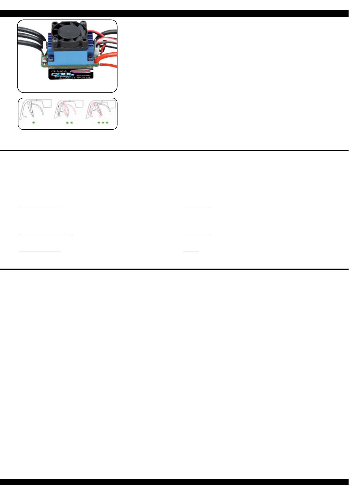
3. E´possibile congurare tre parametri:
• Posizione neutra
• Fine corsa marcia avanti
• Fine corsa marcia indietro
In seguito trovate le immagini,dove sono presentati i processi e le
procedure gracamente.
4. Portare la leva del gas in posizione neutrale e premere il tasto ‚SET‘, il
LED verde lampeggia una volta e il motore emette un suono. Portare la
leva del gas in posizione nale per il movimento in avanti e premere il
tasto `SET il LED verde lampeggia due volte e il motore emette due
suoni. Portare la leva del gas in posizione nale per il movimento indietro
e premere il tasto `SET`, il LED verde lampeggia tre volte e il motore
emette tre suoni. Attendere tre secondi, dopodiché è terminato il
processo di calibrazione.
Calibrating the Throttle/Brake
To ensure that your ESC operates correctly it has to be calibrated. During
this process the full throttle, stop and brake positions will be set. There are 3
occasions when the unit must be calibrated.
• Before using the ESC for the rst time
• If you change to a new transmitter
• If the neutral point or servo throw is changed within your transmitter
To calibrate the system, please proceed as follows:
1. Ensure that the receiver is switched OFF and switch ON the transmitter. If
you are using a Futaba transmitter, please ensure that you have reversed
the throttle function. The throw should be set to neutral. If the transmitter
is tted with an ABS function this must be de-activated.
2. Press and hold down the ‘SET‘ button on the ESC and switch the receiver
switch ON. This will switch the ESC into Calibration’ mode and the LED
will begin to blink. If you fail to release the ‘SET’ button as soon as the
LED blinks, the ESC will enter ‘Programming’ mode. If this happens, you
will have to switch the ESC off and start again to enter ‘Calibration’ mode.
3. 3 Parameters can be set here:
• Neutral point
• Full throttle forwards
• Full throttle reverse
The procedure for setting these 3 points is outlined below:
4. Ensure that the throttle control is in the neutral position and press the
‘Set‘ button. The green LED will ash once and the motor will omit a
beep. Move the throttle control to the full throttle (forwards) position and
press the green ‘Set‘ button. The green LED will ash twice and the motor
will omit 2 bleeps. Move the throttle control to the full reverse position and
press the ‘Set‘ button. The green LED will ash 3 times and the motor will
omit 3 bleeps. 3 Seconds after this procedure has been followed, the
motor is ready for use.
Segnali e dispositivi di sicurezza
Durante il normale funzionamento, i segnali LED hanno i seguenti signicati:
a. Quando l‘acceleratore è in posizione neutra, non è accesa né la LED rossa né la LED verde.
b. Il LED rosso si accende quando il veicolo è in movimento in avanti o indietro. Durante la frenata, il LED rosso
lampeggia velocemente.
c. I LED verde si accende quando il generatore di gas e in max. posizione avanti o indietro.
Tramite segnali d’avviso, il regolatore richiama l‘attenzione su determinate condizioni:
1. Durante l´avvio, il processore controlla la tensione d’ingresso, quando è al di fuori dei limiti consentiti, un tono duale
con una pausa di un secondo tra i singoli segnali „bipbip, bip-bip, bip-bip-“ lo segnala.
2. Quando il segnale d’ingresso non è corretto, sarà generato un suono con una pausa di due secondi tra i singoli
segnali „bip-,-bip, bip-“
Questo regolatore è dotato di una serie di dispositivi di sicurezza per un funzionamento sicuro:
1. Spegnimento sottotensione:
Non appena la tensione di una batteria LiPo, per un periodo di 2 secondi, va sotto la soglia impostata, il motore si
spegne. Notate che il motore non può essere riavviato, se la tensione di una cella è inferiore a 3,5 V.
Batterie NiCd o NiMH con una tensione compresa tra 9,0 V e 12,0 V, sono trattate come una batteria LiPo a tre
celle. Le batterie con meno di 9.0 V come un due-celle LiPo-Pack. Se per esempio, una batteria NiMH ha una
tensione di 8,0 V, e la soglia è impostata a 2,6 V per cella LiPo, l‘arresto avviene a 5,2 V (2 x 2,6 V). Cosi anche le
celle di NiCd, sono efcacemente protetti contro una scarica profonda.
2. Spegnimento per sovratemperatura:
Appena la temperatura del regolatore, per una durata di 5 secondi, supera il valore di 95 ° C, il motore si spegne.
Dopo lo spegnimento, è necessario lasciare raffreddare il regolatore, altrimenti il regolatore sarà danneggiato.
Questa funzione non può essere disabilitata!
3. Segnale d´ingresso difettoso
Se il segnale d’ingresso per un periodo di 0,2 sec è rilevato come errato e motore si spegne.
LED’s, errors and protection
In normal use the LED will illuminate as follows:
a. If the throttle control is in the neutral position, neither the red or green LED will illuminate.
b. The red LED will illuminate if the vehicle is driving forwards or in reverse. If the vehicle is braking, the red LED will
ash rapidly.
c. The green LED will illuminate when the vehicle is at full throttle either forwards or in reverse.
In certain circumstances the ESC will omit an acoustic tone to warn you of a problem:
1. On switching on, the ESC will check the battery pack voltage and if it falls outside the correct values it will omit
double signals followed by a 1 second pause: “beep-beep-, beep-beep-, beep-beep-”
2. If the ESC does not receive a signal from the transmitter it will omit single signal followed by a 2 second pause:
“beep-, beep-, beep-”
The ESC has ben equipped with a series of protective circuits to ensure safe operation:
1. Low voltage cut-off:
If the voltage drops below the set value for more than 2 seconds the ESC will switch the motor off. Please note that
the motor cannot be started again if the voltage is below the choosen value per cell.
If a NiCd or NiMH pack with a voltage of between 9 and 12 Volts is connected, the ESC will treat is as if it was a 3 cell
LiPo pack. If the pack voltage is below 9.0 Volts, the ESC will react as if it was a 2 cell LiPo pack. For example, if a
NiMH pack is connected with a nominal voltage of 8 Volts and the cut-off value is set to 2.6 Volts per cell, the ESC
will switch the motor off at 5.2 Volts (2 X 2.6 V). This will protect the NiMH packs from ‘deep discharge’.
2. Temperature cut-off
If the internal temperature of the ESC rises above 95°C for more than 5 seconds the motor will switch off. After the
ESC switches off it has to cool down before operating again. Otherwise the ESC will be damaged. This function
should not be disabled!
3. Signal loss
If the signal is lost for more than 0.2 seconds the ESC will switch the motor off.
SET-Taste beim Einschalten drücken
Press SET button while switching on
IT - Soluzione dei problemi
Anche se questo controller per modelli d´auto e camion è
sottoposto a un controllo di qualità continuo, possano
manifestarsi dei problemi. Nella tabella seguente sono
elencati i possibili problemi e le relative soluzioni.
Dopo l‘accensione il motore non parte e non rilascia
alcun segnale acustico.
1. La batteria o il collegamento alla batteria non sono in
ordine.
- Controllare i cavi, connettori e batteria.
Dopo l‘accensione, il motore non parte ed emette
un segnale di allarme, un doppio segnale acustico
ogni secondo.
1. La tensione d’ingresso non è corretta, è troppo alta o
troppo bassa.
- Controllare la tensione della batteria.
Dopo l‘accensione, il motore non parte ed emette un
segnale di allarme continuo ogni 2 secondi.
1. Il segnale d’ingresso è identicato come errata.
- Controllare il trasmettitore e il ricevitore, e il lo di
collegamento ricevitore del regolatore.
Il motore gira in una direzione errata.
1. I collegamenti del motore in senso inverso.
- Sostituire due cavi di collegamento tra il motore e il
regolatore.
DImprovvisamente il motore non gira più
1. Il segnale d´ingresso non è corretto.
- Controllare trasmettitore, ricevitore e il cavo servo.
2. La batteria ha una tensione troppo bassa.
- Caricare la batteria.
Funzionamento irregolare del motore, balbetta.
1. Vi è una connessione allentata.
- Controllare tutti i collegamenti in grande dettaglio.
2. La trasmissione radio subisce forti interferenze
intermittenti.
- Ruotare il controllo spento e riacceso. Se ancora
non si ottiene un corretto funzionamento, utilizzare
il vostro veicolo in qualsiasi altro luogo.
GB - Troubleshooting
Although this ESC has been subjected to the most strin-
gent quality control it is possible that you may experience
a problem during operation. In this case please use the
table below to assist in fault nding.
The motor will not rotate after switching on.
No signal is present.
1. The battery pack or battery pack connectors are
faulty.
- Check all of the connectors and the battery pack.
The motor will not turn after switching on. The ESC
omits double signals with a 1 second interval.
1. The input voltage is too high or too low.
- Check the battery pack voltage.
The motor will not turn after switching on. The ESC
omits single signals with a 2 second interval.
1. No or a poor receiver signal.
- Check both the transmitter and receiver as well as
the ESC connecting cable.
The motor turns in the wrong direction.
1. The motor connecting cables are swapped
- Swap 2 of the ESC/motor connecting cables
The motor suddenly stops turning.
1. The battery voltage is too low.
- Charge the battery pack.
2. No signal.
- Check the transmitter, receiver and all of the cables
Only steering response
The motor stutters or runs irregularly.
1. One of the connectors is loose.
- Carefully check all of the connectors.
2. The receiver has intermediate interference.
- Switch the system off and then on. If the interfe-
rence persists, operate the model in another
location.
5
Nota importante:
Oltre ai segnali lampeggianti del LED rosso, sono generati anche segnali acustici dal motore. Al termine di ogni
programmazione, il regolatore deve essere prima spento. Dopo il riavvio, la nuova congurazione avrà effetto. Notate
che dal quinto passo di programmazione, la presentazione è un po’ diversa. Un lampeggio lungo segnala il passo 5,
seguito da altri segnali di breve durata per i passi successivi..
Per esempio, come segue:
Segnale lampeggiante lungo + una volta corto = Programmazione Passo 6
Segnale lampeggiante lungo + due volte corto = Programmazione Passo 7
Segnale lampeggiante lungo + tre volte corto = Programmazione Passo 8, ect.
Important note:
In addition to the red LED blinking, the motor will omit an acoustic signal. After every change to the values the ESC
must be switched off to store the values. The new settings will not be effective until the ESC is re-started. Please
note that program option 5 and above (Professional settings) are slightly different in that they will be indicated by a
long blink rst followed by short blinks.
For example:
Long blink + one short = Program option 6
Long blink + two short = Program option 7
Long blink + three short = Program option 8, etc.
IT - Struttura del menu del regolatore GB - Menu structure
Accendere il trasmettitore
Switch transmitter ON
Tutte le fasi seguenti di programmazione si svolgano nella stessa maniera.
All of the other menu options are accessed in the same manner.
rosso|red LED lampeggia|blinks 1x, ►0 %
rosso|red LED lampeggia|blinks 2x, ►5 %
rosso|red LED lampeggia|blinks 3x, ►10 %
rosso|red LED lampeggia|blinks 4x, ►15 %
rosso|red LED lampeggia|blinks 5x, ►20 %
rosso|red LED lampeggia|blinks 6x, ►25 %
rosso|red LED lampeggia|blinks 7x, ►30 %
rosso|red LED lampeggia|blinks 8x, ►40 %
Il LED rosso lampeggia una volta, cioè, signica andare avanti con freno.
Red LED blinks once indicating forwards and brake.
LED rosso lampeggia due volte, vale a dire, avanti e indietro con freno.
The red LED blinks twice indicating forwards, reverse and brake.
rosso|red LED lampeggia|blinks 1x, ►aus
rosso|red LED lampeggia|blinks 2x, ►2,6 V
rosso|red LED lampeggia|blinks 3x, ►2,8 V
rosso|red LED lampeggia|blinks 4x, ►3 V
rosso|red LED lampeggia|blinks 5x, ►3,2 V
rosso|red LED lampeggia|blinks 6x, ►3,4 V
Si prega di premere il tasto ‚SET‘ per ogni modica del valore corrente,
il LED rosso indica ciascuno dei valori, lampeggiare una volta signica
che è impostato su valore 1, due volte sul valore 2 ecc.
Press the ‘SET‘ button to select the desired value. The red LED will
indicate which value is selected. 1 X blink indicates value 1, 2 x blinks
indicate value 2 etc.
Accendere il regolatore, mentre si
preme il tasto ‚SET‘.
Press and hold the ‘SET‘ button
down and switch the receiver on
Il LED rosso lampeggia
The red LED blinks
Il LED verde lampeggia una volta
The green LED blinks once
Il LED verde lampeggia 2 x
The green LED blinks twice
Il LED verde lampeggia 3 x
The green LED blinks 3 times
Il LED verde lampeggia X x
The green LED blinks X times
Premere il pulsante
per 3 secondi
Press the button
for 3 seconds
Premere il pulsante
per 3 secondi
Press the button
for 3 seconds
Premere il pulsante
per 3 secondi
Press the button
for 3 seconds
Lasciare il
tasto
Release button
Lasciare il
tasto
Release button
Lasciare il
tasto
Release button
Lasciare il
tasto
Release button
Premere
il tasto
Press button
Premere
il tasto
Press button
Premere
il tasto
Press button
Premere
il tasto
Press button
Programmazione Fase 1,
modalità di guida
Program option 1, Drive mode
Fase di programmazione 2,
modalità di frenata
Program option 2, Brake mode
Fase di programmazione 3,
sottotensione
Program option 3, Low voltage cut-off
Phase de programmation X
Program Option
Le caselle grigie mostrano l‘impostazione predenite.
* Non si dovrebbe mai scegliere un tempo troppo alto. il motore e controllori possono essere danneggiati.
A temperature superiori a 80 ° C al motore, la temporizzazione deve essere ridotta o la traduzione regolato
(abbreviato) essere.
The elds which are shaded in grey indicate the factory settings.
* You should never choose a too high timing. The engine and the controller can be damaged. For temperatures above
80 ° C on the engine, the timing must be reduced or the transmission adjusted (shortened).
IT - Programmazione del regolatore GB - Programming the ESC
Fase di programmazione
Program Mode
Valori del programma
Program Value
1 2 3 4 5 6 7 8
Impostazioni di base
Default Setting
1. Modalità di guida
Drive Mode
In avanti freno on
Forwards, brake on
avanti / indietro, freno on
forwards / reverse, brake on
2. Freno
Drag Brake Force
0 % 5 % 10 % 15 % 20 % 25 % 30 % 40 %
3. Sottotensione
Low Voltage OFF 2,6 V/celle
2,6 V/cell
2,8 V/celle
2,8 V/cell
3,0 V/celle
3,0 V/cell
3,2 V/celle
3,2 V/cell
3,4 V/celle
3,4 V/cell
4. Start modo
Start Mode
delicato
soft
normal
normal
aggressivo
aggressive
molto aggressivo
very aggressive
Impostazioni professionali
Professional Settings
5. Forza frenante massima
Brake Max.
25% 50% 75% 100%
6. Velocità massima retromarcia
Max. Reverse
25% 50% 75% 100%
7. Forza frenante min
Brake Force Min.
= Forza freno
= As Brake max.
0 % 20% 40%
8. Zona neutra
Neutral Zone
6% stretto
6% Narrow
9% normal
9% normal
12% largho
12% Wide
9. *Timing
*Timing
0,00° 3,75° 7,50° 11,25° 15,00° 18,75° 22,50° 26,25°
10. Tipo di motore
Motor Type
BL-Motore senza spazzole
Brushless
11. Sovratemperatura
Temp. Cut-Off
95°C No protezione
Off
6
DE
Questo regolatore è dotato di numerose opzioni di congurazione. Per raggiungere il Suo obiettivo di programmazione
ottimale in modo rapido e sicuro, si tiene fede al menu mostrato nella struttura della tabella sopra e le opzioni di
programmazione. Le singole fasi di programmazione della tabella hanno i seguenti signicati:
1. Modalita´di guida
Nel modo gara punto 1, il veicolo sta viaggiando solo in avanti, il freno e´attivato, la marcia inversa e´escluso.
Questa modalità è adatta per le competizioni. In modalità di guida, punto 2 (avanti / indietro con freno), il veicolo
può anche invertire con funzione freno attivato. Questa modalità è adatta per le operazioni normali e per
principianti..
Nota:
Nella 2.modalità di guida, è necessario confermare l´operazione due volte per avere l´effetto d’inversione. Se si
passa la leva in avanti, per la prima volta nella zona inversa, il motore frena. Il veicolo si ferma, ma non
totalmente. Ora, se la leva viene premuto nuovamente nella zona inversa, inverte il veicolo, pero prima si ferma
brevemente. Quando la leva viene nuovamente spostato in avanti, indipendente se il motore è in frenata o in
modalità inversa, la macchina poi viaggia nuovamente in avanti.
2. Freno:
In questo menu, l‘azione minimo di frenatura del freno, viene impostato come valore. Il campo di regolazione è
compreso tra 0 e 40%.
3. Sottotensione
In questo punto po’ essere impostato il valore di spegnimento. L‘intervallo d’impostazione è tra 3,4 - 2,6 V per
cella. Appena è superata la soglia, il regolatore spegne il motore.
4. Start-Modus:
Con questa opzione è possibile impostare come deve essere eseguito la partenza. C’è la possibilità di scegliere
tra 4 modi, diversi, da delicato a molto aggressivo. Si noti che per le modalità „aggressivo e molto aggressivo“ si
deve usare batterie particolarmente potenti con bassa resistenza interna. In caso contrario, avvengono
sottotensione e il motore gira su solo con ritardo. Inoltre, il motore e la trasmissione sono da regolare, secondo
la modalità di avviamento desiderata.
5. Forza frenante massima:
Il regolatore è dotato di un freno che agisce proporzionale alla posizione della datrice. Il più forte effetto si ottiene
quando la leva viene spinto completamente in avanti. Un forte effetto frenante porta il veicolo a un arresto
rapido, che d‘altra parte, è collegato a un elevato grado di usura dei parti meccanici come per esempio
l´ingranaggio.
6. Velocità massima retromarcia:
In questo menu può essere impostata la velocità massima per retromarcia.
7. Forza frenante minima:
In questa fase del programma può essere impostato il grado d’azione del
freno, all‘inizio della fase di frenatura. Nella impostazione predenita è
presente lo stesso valore della forza frenante. (punto 2)
8. Zona neutra:
In questo menu, la gamma della zona neutra può essere specicato. Ci
sono tre possibilità: stretto, normale ed estesa. Le due gure seguenti
illustrano il processo e mostrano le singole aree, sia per Stick, e
attrezzature impugnatura a pistola.
9. Timing:
Per un motore brushless, è importante congurare il timing corretto.
Questo regolatore può essere abbinato in modo optimale. Si prega di
notare i consigli del costruttore. Fondamentalmente, maggiore è la
scelta del timing, maggiore è la potenza del motore, aumentando
notevolmente il consumo di energia.
10. Tipo di motore:
Il regolatore è progettato esclusivamente per l‘utilizzo di motori brushless
(BL),non ci sono altre opzioni in questa zona.
11. Surriscaldamento:
Il regolatore è dotato di un’efcace protezione di temperatura eccessiva. Il
motore viene spento, se la soglia di 95 ° C viene superata per un periodo
di 5 secondi. Questa condizione è indicata dal LED verde lampeggiante.
La funzione non deve essere disattivata.
Per aggirare la programmazione tramite il pulsante Setup, il regolatore può
anche essere programmato facilmente tramite la scheda di programmazione
venduto separatamente (Art.Nr. 08 1453).
GB
This ESC is tted with many useful functions and to help you to be able to make the most of the various options they
are explained below. Please use the programming table shown on page 6 together with these explanations to program
your ESC quickly and effectively:
1. Drive mode:
If option 1 is selected in Drive mode, the vehicle will only drive forwards and the brake is active which make this
mode the best choice for racing. In mode 2 the vehicle can be driven forwards or in reverse and the brake is also
active. This mode is useful for general use and training.
Note:
When option 2 is selected, moving the throttle control back past the neutral point will initially activate the brake. If
the throttle control is then moved back to the neutral position briey the ESC will switch over to reverse. Moving
the ESC forwards will make the vehicle drive forwards regardless of whether it was braking or moving in reverse.
2. Drag Brake force:
In this option the drag braking force can be set. The value is set as a percentage and the values are from 0 to
40%
3. Low voltage:
In this option you can set the low voltage cut-off value. The cut-off voltage can be set between 3.4 and 2.6 Volts
per cell. Once the cut-off voltage has been reached the motor will stop.
4. Start Mode:
With this option you can choose how the vehicle will accelerate when full throttle is applied and you can set the
value between ‘Soft‘ and ‘Very Aggressive‘. Please note that if you select one of the 2 ‘Aggressive’ modes that
you will need to have batteries with a very low internal resistance otherwise the voltage will drop due to the high
current draw and the motor may stutter. Also ensure that your motor and gearing are capable of carrying the high
loads.
5. Brake Max.:
The ESC is equipped with a braking system which works proportionally to the throttle control. This means that
the further the throttle control is moved rearwards the more braking force will be applied. A higher value here will
mean that the vehicle will brake harder but more strain will be placed on the components, for example, the
gearing.
6. Max. Reverse:
This option is used to adjust the top speed when driving in reverse
7. Brake Force Min.:
The effect that the brake has when rst applied can be set here. The default
setting will be whatever
8. Neutral Zone:
The ‘neutral Zone’, which is the area between forwards and reverse or braking
can be set to ‘Narrow’, ‘Normal’ or ‘Wide’ as shown in the illustration below.
This Zone can be set for both ‘stick’ or ‘pistol-grip’ type transmitters as shown.
9. Timing:
It is important that the correct timing is selected for a Brushless motor and you
can set the timing here. Please refer to you motor’s instructions for the correct
setting. As a rule of thumb, raising the timing will increase the output of your
motor but at the cost of a higher current draw end heat developing
10. Motor Type:
This ESC has been exclusively designed for use with Brushless motors and
so you cannot make any changes here.
11. Temp. Cut-Off:
The ESC is equipped with an accurate temperature sensor which will switch
the unit off if a temperature of 95°C is exceeded for 5 seconds or more. This
situation will be indicated by a ashing green LED. This function should not be
disabled.
To avoid the programming procedere with the set up botton, you can all so use the
seperatly available Programmcard (Ord.No. 08 1453).
max. avanti
Max. forwards
Zone per
andare avanti
Forwards zone
Zone per andare avanti
Neutral zone
Zone per andare avanti | Neutral zone
Punto neutro
Neutral point
Punto neutro | Neutral point
Zona per freni e invertire
Brake and reverse zone
Zona per freni e invertire
Brake and reverse zone
Forza frenante massima
Max. Braking effect
Forza frenante massima
Max. Braking effect
max.
avanti
Max.
forwards
Modello non risponde
1. Batterie scariche o difettose
- Caricare, sostituire le batterie
2. Motore difettoso
- Sostituire il motore
3. Cavi allentato o danneggiato
- Ricollegare o sostituire i cavi
4. Trasmettente spenta, danneggiato o perso il binding
- Accendere la trasmittente o rieffettuare il binding
5. Ricevente diffettoso
- Sostituire la ricevente
6. Regolatore di velocità difettoso oppure non correttamente collegato
- Sostituire oppure ricollegare il regolatore
Modello reagisce in maniera incontrollata
1. Trasmettente spenta, danneggiato o perso il binding
- Accendere la trasmittente o rieffettuare il binding
2. Regolatore programmato non correttamente
- Riprogrammare il regolatore
3. Ricevente diffettosa
- Sostituire la ricevente
Motore reagisce in modo strano appena acceso la trasmittente
1. Fail Safe male impostato
- Riprogrammare il Fail Safe
2. Trim del Gas non in posizione neutrale
- Trimmare il Gas
Modello va solo in avanti
1. Regolatore programmato non correttamente
- Riprogrammare il regolatore
Reagisce solo il sterzo ai comandi
1. Regolatore oppure motore diffettoso
- Sostituire il regolatore oppure motore
Sterzo non risponde
1. Servo sterzo diffettoso
- Sostituire il servo sterzo
2. Dualrate non impostato correttamente
- Impostare Dualrate
3. Leva del sterzo sporco
- Pulire la leva del sterzo
Forte rumore dalla trasmissione
1. Ingranaggio principale, pignone o differenziale danneggiati
- Non continuare la guida! Sostituire la parte difettosa
2. Distanza pignone corona non impostata bene
- Controllare il giocho tra pignone - corona
Regolatore di velocità si spegne durante la guida
1. Blocco della sottotensione, tensione batteria bassa
- Caricare la batteria
2. Spegnimento per temperatura eccessiva
- Fare raffreddare il regolatore di velocità
Perdita dei cardani anteriore
1. Larghezza carreggiata elevata
- Riduree la distanza
Model does not respond
1. Battery or batteries empty or defective
- Charge battery or replace
2. Motor broken
- Replace motor
3. Loose or damaged cable
- Reconnect cable or replace
4. Transmitter turned off, lost or damaged binding
- Transmitter back on, bind or replace
5. Defective receiver
- Replace receiver
6. Speed controller is defective or connection issue
- Connect properly or replace
Model react uncontrolled
1. Transmitter turned off, lost or damaged binding
- Transmitter back on, bind or replace
2. Controller not calibrated or programmed incorrectly
- Recalibrate or reprogram
3. Defective receiver
- Replace receiver
Engine is running when you turn on inadvertently
1. Incorrectly set Failsafe
- Failsafe program to neutral
2. Throttle trim on the transmitter is not in neutral
- Throttle trim set to neutral
Model moves forward only
1. Controller not calibrated or programmed incorrectly
- Recalibrate or reprogram
Only steering response
1. Regulator or Motor is defective or not Calibrated
- Calibrate speed controller or replace motor
Steering does not respond
1. Power steering defect
- Replace servo
2. Dual Rate on the transmitter set too low or to 0
- Dual rate increase
3. Very dirty steering lever or steering knuckle -
Clean and lubricate well
Loud noise from the drive
1. Main gear, pinion or differential damage
- Do not continue! affected part needs to be replaced
2. Incorrect gear mesh
- Reset gear mesh
Speed controller shuts off while driving
1. Low voltage cut-off, battery voltage too low
- Charging the battery
2. Overtemperature
- Let speed controller cool
Front drive shafts fall out
1. Too large track width
- Track width reduction
IT - Risoluzione dei problemi | GB - Troubleshooting
7
LED
Informazione di sicurezza
• Proteggere il caricatore da polvere, sporcizia, umidità e raggi solari.
• Non disporre il caricatore e il pacco batteria su sottofondo inammabile
• Evitare il corto circuito e fare attenzione alla polarità
• Non caricare e/o scaricare pacchi batteria con una temperatura elevate. Prima di caricare/
scaricare il pacco batteria, farlo raffreddare
• Non usare caricatori difettosi
• Non caricare pacchi batterie difettosi
• Rispettare le norme del fornitore delle batterie
Safety Information
• Never expose the charger to moisture or direct sun light.
• Never leave the charger unattended when in use, and always operate it on a re proof surface.
• Avoid short circuits at all costs. Always observe the correct polarity.
• Batteries should always be allowed to cool down before you charge or discharge them.
• Never try to charge/discharge damaged charger.
• Never try to charge/discharge damaged packs or cells.
• Follow the directions given by the battery manufacturer.
Manuale Caricatore
1. Collegare il caricabatterie alla presa di corrente. Il LED sul carica batteria indica la disposizione
per il caricamento.
2. Collegare il caricabatterie (B) alla batteria (A). Il LED si spegne e viene visualizzata la ricarica.
La ricarica completa di una batteria scarica è di circa 2 ~ 3 ore a seconda della capacità della
batteria.
Tempo di carica
Questo dipende della capacità dell pacco batterie
Esempio:
Corrente di carica = 0,8A/h (800mAh)
Capacità batteria = 800 mAh
Tempo di carica = 1 Stunde (h)
Operating Instructions Carger
1. Connect the charger to the AC Network and plug it into a grounding receptacle. The LED on the
charger will indicate it is ready for charging.
2. Connect the charger (B) to the battery pack (A). The LED will change the color to show it is
charging. If the battery pack is completely empty, a full charge process will take approx.
2 ~ 7 hours, depending on the batteries capacity. Once the LED changin the color again, charge
has been completed.
Charging Time
The charging time varies depending on the capacity of the battery.
Example:
Charge current = 0.8 A/h
Battery Capacity = 800 mAh
Charging time = 1 hour (h)
Attenzione:
Usare il caricatore solo con pacchi batterie adatte. Pacchi batterie adatto sono batterie al Lithio
Polymero con max. 2 Celle, max. 7,4V tensione e max. 5000mAh. Il pacco batteria deve avere
un cavo bilanciatore del tipo JST-XH. Il caricamento di batterie non adatte rischia di danneggiare
il caricatore e c’è rischio di bruciare il pacco batteria. Attenzione, rischio d’incendio! È proibito di
modicare il cavo bilanciatore.
Caution:
Only charge suitable battery‘s with this charger. Suitable battery‘s are lithium polymer battery‘s with
max. 2 cells, max. 7.4 V nominal voltage and max. 5000mAh. The battery must have a balancer
plug type JST-XH. The charging of unsuitable battery‘s can cause damage to the charger and the
battery‘s. Fire Hazard! The balancer plug of the charger is not allowed to get altered or soldered to
a different balancer plug type!
Montaggio differenziale anteriore
Front gear assembly diagram
50 5078
50 5075
50 5073
50 5071
50 5074
50 5072
50
5085
50 5076
07 9989
No. 50 5155
Diff. ant./post. completo
Differencial complete
No. 50 5155
Diff. ant./post. completo
Differencial complete
Montaggio differenziale posteriore
Rear gear assembly diagram
50 5078
50 5075
50 5074
50 5073
50 5024
50 5145
50 5023
50 5024
50 5076
50 5071
50 5085
07 9989
07 9996
07 0806
8
Montaggio sterzo e braccetti inferiori
Steering assembly diagram
50 5080
50 5081
50 5079
50 5100
07 9989
50 5099
07 9996
50 5028
Prima dell’uso del prodotto si prega di vericare tutti i bullo-
ni di collegamenti della parte elettronica.
Il veicolo dispone di una sospensione anteriore Pivot Ball.
Questo ha numerosi vantaggi. E ‚molto robusto e di facile
manutenzione. L’impostazione di fabbrica non permette
che gli alberi di trasmissione saltano fuori durante la guida.
Per qualsiasi modello in azione, delle parti meccanica si
possono allentare tramite i vibrazioni. Un minimo gioco può
essere sufciente che durante la guida si perdono gli al-
berini. Pertanto, è anche necessario assicurarsi che tutti
i bulloni, dadi e vite siano controllati prima di ogni utilizzo.
Con la vita a sfera (cod. 505081 vedi lista di ricambio) si
regola il giusto ssaggio di questa parte meccanica. Con-
sigliamo di avvitare la vita superiore e inferiore nel stesso
modo, in modo di non causare un bloccasterzo (tramite gli
alberi di trasmissioni) durante la manovra di sterzo. Ma di
fare anche bene attenzione di non lasciare un gioco troppo
grande, altrimenti si rischia di perdere gli alberi di trasmis-
sione. La calotta esterna in plastica a (505080) serve solo
per ssare il fuso a snodo sulla vite a sfera.
Consigliamo di non avvitare questo coperchio in modo trop-
po serrato.
Before each use make sure to check all bolt connections
and cable connections. Your vehicle has a pivot front sus-
pension. This has a number of advantages. It is very ro-
bust and easy to maintain. The set-up of the car has been
done so the drive shaft will not pop out. As with any model,
screws and bolts can losen during break-in of the car. This
can result in tolerance of the drive shaft. The drive shaft
can then pop out if high pressure is applied. The inner ball
screw (item No.: 505081) will enable you to adjust the to-
lerance resulting in ne adjustments of the track width. For
best results when setting up the pivot ball for the rst time,
please always adjust the upper and lower pivot in the same
way. Fasten as far as the pivot can still be pulled up and
down easyly but not as far that it will pop out if you give full
steering angle. The outer plastic socket screw (item No.:
505080) is only used for securing of the steering knuckle.
This should not be too tight, otherwise the steering is not
smooth and the handling can be adversely affected.
50 5054
50 5097
50 5087
50 5054
07 9989 50 5082
07 9996
50 5028
Montaggio assetto posteriore
Rear shaft assembly
9
Montaggio ammortizzatori
Shock assembly
50 5064
Montaggio Servo Saver
Buffer assembly
50 5029
10
Montaggio piastra radio
Buffer assembly
03 3215
07 9841
50 5093
50 5027
Montaggio Motore
Motor assembly
50 5126 (22 Z./T.)
50 5026
08 1460