manuals.online logo
Brands
  1. Home
  2. •
  3. Brands
  4. •
  5. Jamara
  6. •
  7. Toy
  8. •
  9. Jamara Air Trainer 46 User manual

Jamara Air Trainer 46 User manual

20/16
IT - Informazioni generali
Jamara e. K. non e´responsabile per danni, sostenute al prodotto stesso o attraverso questo, dovuti
ad una gestione non corretta del articolo. Solo il cliente si assume la piena responsabilità per la
manutenzione e l´utilizzo corretto dello stesso; questo include il montaggio, la ricarica, l´utilizzo,
no alla scelta della aerea di applicazione. Si prega di notare e rispettare le istruzioni d´uso, questi
contengono informazioni e avvertimenti molto importanti
ATTENZIONE!
In molti paesi l‘ impiego di modelli radiocomandati richiede una assicurazione obbligatoria. Infoirma-
tevi perciò presso il vostro assicuratore o poresso il vostro negoziante di ducia.
GB - General Information
Jamara e.K. is not liable for any damage caused to the product itself or through this, provided this
is due to improper operation or handling errors. The Customer alone bears the full responsibility for
the proper use and handling, including without limitation, the assembly, the charging process, the
use and choice of the operation area. Please refer to the operating and user instructions, it contains
important information and warnings.
Attention!
In some countries it is a legal requirement to carry third party indemnity insurance when operating
a radio controlled model. Please ask your local dealer, governing body or your insurance company
for details.
Articolo di modellismo – Non è un giocattolo
Adatto a persone dai 14 anni in su.
Attenzione: Non adatto a bambini sotto i 36 mesi. PERICOLO DI SOFFOCAMENTO.
Contiene piccole parti che possono essere inghiottite.
Tenere lontano da bambini piccoli.
GB - This model is not a toy!
Not suitable for people under 14 year.
Warning: Not suitable for children under 36 months. RISK OF SUFFOCATION!
Contains small parts which can be swallowed.
Keep away necessarily from children.
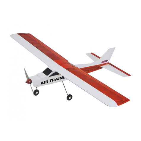
No. 006144 Air Trainer 46
DE - Istruzioni di montaggio
GB - Instruction
Highlights:
• Fusoliera in balsa e compensato • Ala centinata in costruzione tradizionale
• Kit in legno • Ideale per principianti • Taglio a Laser
Funzioni: • Alettone • Profondità • Direzionale • Motore
Contenuto del kit: • Modello • Ruote • Filo metallico per carrello • Scatola ricca di accessori
• Istruzioni/Piani di costruzione
Accessori consigliati:
Motore elettrico A2820/6 13 2820
Elica APC 10 x 7 34 0061
4 x Servi Nitro Q7 JR 03 3215
3 x Servi elettrico Q7 JR 03 3215
Batteria 14,8 V 3700 mAh 14 1380
Trasmittente FCX 6 Pro Tel 2,4 GHz 06 1260
Dati tecnici:
• Apartura alare: ~ 1600 mm • Lunghezza ~ 1240 mm • Peso: ~ 1900 g
S.E. & O.
Highlights:
• Fuselage made of balsa and plywood • Wings made of wood in rib construction
• Wooden construction kit • Ideal to have with you at all times • Laser cut kit
Functions: • Aileron • Elevator • Vertical n • Throttle
Box contents: • Modell • Wheels • Undercarriage • Accessories • Instructions/Planes
Recommended accessories
Electric motor A2820/6 13 2820
Propeller APC 10 x 7 34 0061
4 x Servos Nitro Q7 JR 03 3215
3 x Servos Electric Q7 JR 03 3215
Battery 14,8 V 3700 mAh 14 1380
Transmitter FCX 6 Pro Tel 2,4 GHz 06 1260
Technical data:
• Wing span: ~ 1600 mm • Length: ~ 990 mm • Weight: ~ 1240 g
No responsibility is taken for the correctness of this information. Subject to change without prior
notice. Errors and omissions excepted
Montaggio dell‘ala destra
Attenzione!!
L‘ala è la parte più importante del tuo aereo, lavora molto attentamente con l‘incollaggio,
prenditi il tuo tempo per fare tutto correttamente!
The following steps are showing right wing.
Caution!!
Main wing is one of the most important parts of air plane. Adhering slip-o󰀨 between the right
and the left wings may give a great inuence upon the ying performance and your airplane
may come apart while ying due to incomplete adhering. Accurately build the wings and
completely adhere them.
Montaggio dell‘ala destra
Posizionare le parti W3 e W2 sul piano di lavoro. Posizionare
il listello W3 sul fondo di W2. Utilizzare un angolo per incollare
saldamente il listello.
Nota: Assicurarsi che le due parti (W2 e W3) siano ad un angolo
di 90° l‘una dall‘altra.
The following steps are showing right wing.
Place the W3 hard wood strip and W2 on the working table. Use
instant glue to secure the W3 on the bottom of W2; make sure
the alignment of both bottom lines.
Hint: you can use triangle ruler when secure W3 on W2.
Fissare le centine delle ali W8 - W9 (vedi piano di sequenza) al
longherone (longherone principale W2/W3). Dopo aver ssato le
centine ai longheroni, allinearle con un angolo di 90° rispetto al
longherone principale e incollarle.
Refer to the assemble drawing inside the box and t ribs W8
– W9 onto the W2 combination. Use triangle ruler between the
ribs and W3; make sure the angle is 90 degree and drop some
instant glue to secure ribs in place.
Incollare il listello W2 alla parte superiore del listello principale.
Try to t W2 on the top of the middle beam and use instant glue
to secure it in place.
2
Incollare il componente W5 all‘estremità sinistra del longherone
principale come mostrato in gura.
Try to t W5 on the indicated locations as the pictures show.
Ora incollare il listello nasale W1 sulle centine alari anteriori. As-
sicurarsi che il listello nasale a sinistra e a destra sia rivolta dritto
verso longherone principale.
Try to t W1 onto the ribs combination. Place 1 meter long
straight rule in front of the leading edge. Drop some instant glue
to secure W1 in place.
Allineare le centine delle ali alla W4R e premere nei incavi pre-
viste. Ora incollare le centine delle ali con un po‘ di colla. (W4L è
necessario per l‘ala sinistra).
Try to t the rear edge of the ribs into the slots on W4R and make
sure the W11 is aligning to the side edge of W4R; drop some
instant glue to secure W4R in place. (W4L is the rear edge for
the left wing.)
Girare l‘ala in modo che la parte inferiore dell‘ala sia rivolta verso
l‘alto. Posizionare W11 (albero servo) sull‘ala e incollarlo in po-
sizione con la colla.
Turn the main wing up-side down. Try to t W11 onto the main
wing and secure it in place with some instant glue.
Incollare W12 con precisione sulla supercie di W11.
Try to t W12 on the top of W11 and drop some instant glue to
secure it in place.
Tavolato di supercie:
Posizionare le parti W13, W14 e W15 come mostrato sopra
sul piano di lavoro. Allineare a lo e ssare con un po‘ di colla.
Carteggiare accuratamente con carta vetrata i residui di colla e
le irregolarità.
Top planking:
Try to t W13, W14 and W16 in order. Make sure they are align-
ment and drop some instant glue to secure them in place. Use
sanding paper to trim the surface.
Inserire W7-1 e W7 nel longherone principale W2 e incollarli in
posizione.
Fit W7-1 and W7 into W2 and drop some instant glue to secure
it in place.
Inserire W6-1 e W6 a sinistra nel longherone principale W2. Per
posizionare correttamente i due componenti, prendere come mi-
sura W6-2. Ora incollare le parti con la colla.
Fit W6-1 and W6 into W2. Use W6-2 as a gauge and secure
them in place with glue.
Fissare ora il W10 all‘esterno dell‘ala con una quantità su󰀩ciente
di colla.
Try to t W10 onto the main wing and secure it in place with
some instant glue.
Tavolato inferiore:
Posizionare le parti W13, W15 e W16 come mostrato sopra
sul piano di lavoro. Allineare a lo e ssare con un po‘ di colla.
Carteggiare accuratamente con carta vetrata i residui di colla e
le irregolarità.
Bottom planking:
Try to t W13, W15 and W16 in order. Make sure they are align-
ment and drop some instant glue to secure them in place. Use
sanding paper to trim the surface.
Posizionare l‘ala con il lato superiore verso il basso sul posto di
lavoro. Applicare la colla su tutte le centine, listelli d´aiuto, long-
herone principale e longherone posteriore.
Place the main wing up-side down and spread the white glue
on all ribs.
Posizionare il tavolato inferiore sull‘ala e assicurarsi che il tavola-
to sia correttamente allineato.
Place the bottom planking on the main wing and make sure the
edges are alignment.
3
Girare l‘ala in modo che il tavolato si trovi sul piano di lavoro.
Appesantire l‘ala mentre la colla si asciuga, con dei pesi.
Turn the main wing bottom-side down. Place some heavy objects
on the main wing and wait for the glue to dry enough.
Rimuovere con cautela il fasciame sporgente con un coltello.
Use hobby knife to trim the extra planking.
Applicare la colla sull’ala della parte superiore tutte le centine
anteriore, il listello di supporto, il longherone principale e il long-
herone posteriore.
Spread the white glue on all ribs.
Durante il processo di essiccazione, ssare il pezzo da lavorare
con i morsetti.
Use clips to hold the joiners in place for temporary.
Quando il tavolato si è asciugato, rimuovere il tavolato sporgente
con un coltello.
When the glue on the top planking is dried enough; use hobby
knife to trim the extra planking.
Carteggiare accuratamente con carta vetrata i residui di colla e
le irregolarità.
Use planer and sanding paper to trim the leading edge.
Posizionare il tavolato sulla parte superiore dell‘ala e assicurarsi
che il tavolato sia correttamente allineato.
Place the top planking on the main wing and make sure the
edges are alignme
Appesantire l‘ala mentre la colla si asciuga, con dei pesi. Fissare
l‘ala al piano di lavoro in modo che non scivoli.
Place some heavy objects on the top planking and wait for the
glue to dry enough. If some parts are curved, use pins to hold
them in place for temporary.
Rimuovere 3 x W29 (connettori dell’ala) dall‘imballaggio. Appli-
care un po‘ di colla come mostrato nella gura sopra e incollare
insieme.
Place 3 pieces of wing joiners on the working table. Use white
glue to secure them into one combination.
La centinatura della radice deve essere a lo con il tavolato del
pezzo W19.
The shape of the leading edge must be the same as W19.
Carteggiare accuratamente con carta vetrata le irregolarità della
centina interna della radice.
Use sanding paper to trim the wing root.
Controllare l‘angolo di W6 con il componente W6-2.
Use W6-2 to check the angle of W6.
4
Carteggiare accuratamente con carta vetrata le irregolarità della
centina esterno della radice.
Use sanding paper to trim the wing root at and even.
Rimuovere le parti W17 e W18. Applicare la colla sulla supercie
smussata del W17 e in collare con W18 come mostrato sopra.
Place W17 and W18 on the working table. Use instand glue to
secure the W17 onto W18 as the picture shown.
Posizionare le piastre di rinforzo (W18/17) e il rinforzo delle cen-
tinei (W19) sull‘ala e incollarle.
Try to t the W19 and W18 onto the main wing. Use instant glue
to secure them in place.
E󰀨ettuare un foro attraverso l‘ala. Prendere un trapano da 4,2
mm e praticare il foro preforato in W18 attraverso l‘ala.
According to the hole on the W18, use 4.2mm driller to open a
vertical hole on W18 through the whole main wing.
E󰀨ettuare un foro attraverso l‘ala. Prendere un trapano da 4,2
mm e praticare il foro preforato in W18 attraverso l‘ala.
When complete the assembly of the left and right main wing, iron
the covering your preferred.
Montaggio della fusoliera
Prendere F3 e F4 dalla confezione. Incollare F3 e F4 insieme.
Assicurarsi che l‘incavo (in alto a sinistra) sia perfettamente alli-
neato tra loro. Rimuovere l‘adesivo in eccesso.
Fuselage assembly
Place F3 and F4 on the working table. Please note there is con-
cave mark on their top left side. Place F3 on the top of the F4
with concave mark on the same location applies white glue to
secure them together.
Inserire ora il connettore del ala (W29) nell‘incavo della centina
della radice. Se questo non si adatta perfettamente, carteggiare
con carta vetrata.
Try to t the wing joiner into the main wing. If they cannot t per-
fect, use sanding paper to trim the contacting area.
Per la punta dell‘ala, prendere W21, W22, W23, W24, W25 e
W25-1 e posizionare sul piano di lavoro. Incollare le parti insieme
e incollarle alla centina della radice esterna dell‘ala.
Place W21, W22, W23, W24, W25, W25-1 on the working table
for assembling the wing tip. Use instant glue to secure these
parts in place.
Per completare la punta dell‘ala (W25-1) sono necessari un col-
tello e una carta vetrata.
Use sanding paper and hobby knife the trim the edges of W25-1.
Dopo che l‘adesivo si è asciugato, posizionare il supporto del
carrello di atterraggio per l‘unità di coda su F3. Assicurarsi che
la parte sporgente della sta󰀨a sporga oltre il bordo (vedi foto).
Fissare il carrello del naso con viti M3 x 15 mm e ssare con
rondelle da 3 mm e dadi M3.
When the glue is dried enough, place nose gear mount on
F3 with the longer side face outside. Insert M3x15mm screws
through the nose gear mount, F3 and F4, secure with 3mm
washers and M3 nuts.
Applicare la colla su F5 sulla parte superiore di F6. Accertarsi
che le parti si adattino perfettamente l‘una all‘altra
Place F5 on the top of F6, pay attend to the concave marks must
match each other; apply white glue to secure them together.
Per il ssaggio dell‘ala, posizionare 2 x F18 sul piano di lavoro,
ricoprirne uno con colla e incollarlo insieme.
Apply white glue to secure 2 pieces of F18 together.
5
Applicare della colla attorno ai fori di F8. Inserire con cautela i
dadi M3 nei fori con un martello. Applicare della colla attorno ai
bordi dei dadi.
When the glue on F8 is dried enough, nail the clutch nail. It is
better to drop some instant glue around the clutch nail for re-
inforcement.
Applicare della colla attorno ai fori di F8. Inserire con cautela i
dadi M3 nei fori con un martello. Applicare della colla attorno ai
bordi dei dadi.
Place F2R, F1, F1 and F2L in order as displaying on the picture.
Use white glue to secure F2R to F1 and F2L to the second F1.
Please note the edges must be alignment.
Notare i ssaggi.
Please refer to the attachment #A.
Posizionare i telai (F9/F10 e F11) nella fusoliera come mostrato
in gura e stabilizzare il tutto tra le singole pareti con elastici.
Attenzione! Non incollare ancora! Assicurarsi che i telai siano
allineati correttamente.
Try to t F9 – F11 into the fuselage. Please don‘t apply any
glue.
Collegare le due parti laterali all‘estremità della fusoliera con un
morsetto. Si noti che l‘allineamento delle due parti laterali è lo
stesso alla ne siano uguali e incollarle insieme con la colla..
Please pay attention to the tail on the fuselage. The ends must
be alignment. Drop some instant glue to secure the ends the
fuselage together.
Se tutto è perfettamente allineato, i telai (F3/4, F6 e F8) possono
essere incollati nei punti di contatto.
Use instant glue to secure F3/4, F6 and F8 on side planking.
Inserire F3/4, F6 e F8 nei rispettivi incavi della F2R. Il marchio di
F3 deve puntare verso l‘esterno. Non incollare! Posizionare la
tavola della batteria F13 su F3/4 e F6.
Try to t F3/4, F6 and F8 onto the F2R. Please don‘t use glue
to secure them right now. Fit battery planking F13 onto the
F3/4 und F6.
Assicuratevi che le piccole rientranze su F13 e F3/4 siano sullo
stesso lato e puntate su F2R. Se F13 è posizionato correttamen-
te, può essere incollato con F3/4
Please note the concave mark on F13 will near to the rewall
and face the right side of the fuselage. Make sure the direction
is correct and apply glue on the contacting area of the rewall.
Assicuratevi che le piccole rientranze su F13 e F3/4 siano sullo
stesso lato e puntate su F2R. Se F13 è posizionato correttamen-
te, può essere incollato con F3/4.
Try to t the F1 and F2L onto the fuselage. Use rubber band to
hold them in place for temporary.
Se i telai F9, F10 e F11 sono perfettamente allineati, possono
essere incollati anche nei punti di contatto.
Try to t , F9, F10 and F11 into the fuselage. Please
don‘t apply any glue.
Girare la fusoliera in modo che la parte inferiore della fusoliera
sia in alto. Applicare l‘adesivo nel punto di contatto di F6 e F13.
Place the fuselage up-side down. Drop some instant glue on the
contacting area of F6 and F13.
Inserire la tavola servo (F14) nella fusoliera dall‘alto e incollarla
davanti al telaio F8.
Fit the F14 into the fuselage and drop some instant glue on every
parts which will contact F14 for securing it in place.
ab
6
Posizionare ora l‘attacco dell‘ala F18 all‘interno della fusoliera e
incollarlo con la colla.
Fit the F18 into the fuselage and drop some instant glue on every
parts which will contact F18 for securing it in place.
Posizionare ora l‘attacco dell‘ala F18 all‘interno della fusoliera e
incollarlo con la colla.
Fit the F19 into the fuselage and drop some instant glue on every
parts which will contact F19 for securing it in place.
Incollare 1 x F12 a F3/4 e i lati della fusoliera dall‘interno per il
rinforzo.
Fit F12 (reinforcing strip) on the contacting area of backside of
rewall and side planking. Apply epoxy to secure it in place.
Collocare F15 sopra la fusoliera e incollarla con la colla.
Use instant glue to secure the F15 on the fuselage.
Utilizzare la colla per incollare i pannelli sul fondo della fusoliera.
Fit the bottom planking F20 on the fuselage and use instant glue
to secure it in place.
Posizionare il nestrino posteriore della cabina F21 sulla fusolie-
ra e ssarlo con la colla.
Place the rear window F21 on the fuselage and sue instant glue
to secure it in place.
Inserire il supporto del carrello nella parte inferiore della fusoliera
nell‘apposito incavo. Se il supporto è posizionato correttamente,
è possibile incollarlo in posizione con la colla.
Please t the main gear mount F16 into the preserved location
on the bottom of the fuselage. When satisfy the location use ins-
tant glue to secure it in place.
Collocare dal basso un rinforzo (F17) sul supporto del carrello
(F16) e incollarlo insieme con la colla.
Place the fuselage top-side up. Fit the F17 on the contacting area
of F16 and side planking. Use instant glue to secure in place.
Collocare dal basso un rinforzo (F17) sul supporto del carrello
(F16) e incollarlo insieme con la colla.
Please take the 1:1 drawing as a reference and drill 4.2mm hole
in F16.
Come mostrato sopra, il fasciame superiore F22 viene incollato
sul lato superiore della fusoliera.
Place the top planking F22 on the tail of fuselage and use instant
glue to secure it in place.
Come mostrato sopra, il fasciame superiore F22 viene incollato
sul lato superiore della fusoliera.
Place the bottom planking F23 on the tail of fuselage and use
instant glue to secure it in place.
Prendere le due parti di F28 e incollarle insieme a lo.
Use instant glue to secure two pieces of F28 together.
7
Piegare con cura le parti F24 e F25 lungo la linea segnata. Evita-
re di rompere le due parti. Inserire F26 a sinistra e a destra negli
incavi di F24/F25 e ssarli con la colla.
Bend the F24 and F25 according to the marked line. Try to t F26
onto the F24/F25. Please note the direction. Use instant glue to
secure them in place.
Installare F28 a F27 come mostrato sopra. Tra la F28 e la F27 si
deve mettere una piccola molla sul perno di bloccaggio.
Please take the picture as a reference when assemble F28 onto
F27, place a small spring between F27 and F28, insert the pop
rivet. Please note the direction of F27.
Far passare la leva corta del perno di bloccaggio attraverso
l‘incavo di F24 e inserire le estremità di F27 nella posizione pre-
vista per F26. Incollare le parti in legno con la colla.
Try to t the combinations of previous two steps together. Please
pay attention to concave mark. Use instant glue to secure them.
Montaggio del piano di coda laterale
Posizionare il V1, V2 e V3 sul piano di lavoro. Carteggiare even-
tuali irregolarità con carta vetrata, ma fare attenzione a non
carteggiare troppo. A󰀩lare i bordi esterni arrotondati.
Assembly Rudder
Use planer and sanding paper to trim the edges of V1, V2, V3
and makes the angle of chamfer around R6 mm.
A󰀩lare i bordi di V1 e V2 in modo che le due parti si incastrino
a lo.
Use sanding paper to trim the surface where V1 meets V2.
Incollare V1 e V2 insieme.
Use instant glue to secure V1 on V2.
Posizionare ora il coperchio della cabina nella parte ante-
riore della fusoliera e segnare l‘estremità come mostrato
nell‘immagine sopra.
Place the front window on the fuselage. Please pay attention to
marked line.
A󰀩lare i bordi della fusoliera a forma rotonda (3 mm) e anche
la supercie a lo.
Use sanding paper to trim the side planking and makes the angle
of chamfer around R3 mm.
Piano di coda
A󰀩lare le superci del piano di coda in modo che sia liscio e
uniforme. I bordi sono arrotondati (6 mm).
Tailplane
Use planer and sanding paper to trim the edges of horizontal and
makes the angle of chamfer around R6 mm.
Posizionare la fusoliera nita sul piano di lavoro e controllare
che tutte le parti siano incollate tra loro e che nulla sia scivolato.
Place the whole fuselage on the working table for checking if
there‘s any bending or un-smooth place. If yes, please check the
whole assembly steps.
Se si desidera far funzionare il modello con un motore a com-
bustione, si raccomanda di sigillare il telaio anteriore (F3/4) con
resina epossidica.
If this plan is intended for engine or Gas engine; please apply
epoxy on planking inside the head and rewall for preventing
the oil.
Ora è possibile coprire la fusoliera, i piani di coda e la copertura
della fusoliera con una pellicola.
Iron on covering on the fuselage, horizontal, vertical and front
window.
8
Una volta che avete coperto la fusoliera, i piani di coda, iniziate
a montare il modello.
After you have covered the fuselage, the wings and tail, you start
with the assembly of the model.
Piegare le cerniere del timone in modo che si muovano liber-
amente.
Bend the plastic hinge so it can move freely.
Applicare la colla sulle cerniere del timone. Assicurarsi di appli-
care la colla su entrambi i lati delle cerniere del timone. Inserire
le cerniere del timone nell‘alettone.
Use epoxy to secure the hinges into the aileron and main wing.
Copertura e completamento del modello Covering and complete the model
Utilizzare un coltello per rimuovere la pellicola nella zona dei
passacavi.
Use hobby knife to remove the covering over the hole for servo
tray and plug exit on the main wing.
Rimuovere la pellicola nell‘area degli alberi servo e stirare i bordi
con un ferro da stiro.
Use iron to trim the edges of the servo tray and plug exit.
Tagliare la pellicola sopra l‘incavo del braccio del servo sul
coperchio dell‘albero del servo. Osservare la posizione in cui si
installa il servo.
Remove the covering over the slot on the servo planking.
Incollare le cerniere del timone nel piano di coda.
Use epoxy to secure the hinges into the elevator and horizontal.
Incollare le cerniere del timone nel piano di coda laterale.
Use epoxy to secure the hinges into the rudder and vertical.
Posizionare le seguenti parti sul piano di lavoro.
• Braccio servo • Tiranteria di collegamento • M3 x 4 mm Vite
senza testa • Dado in plastica • 2 mm Asta lettata • Tubo es-
sibile in silicone • Testa forcella • Timone • Viti M2 x 15 mm • 2
mm Dado.
Praticare un foro di 2 mm nel braccio del servo. Inserire la tiran-
teria di collegamento del braccio servo e ssarlo con una vite di
serraggio M3 x 4 mm e il dado in plastica.
La tiranteria di collegamento non avvitare troppo stretto, deve
muoversi liberamente. Avvitare la testa della forcella sull‘asta
lettata da 2 mm e far scorrere un pezzo di tubo in silicone
sull‘asta. Allineare le squadrette del servo spingendo le viti M2 x
15 mm attraverso i fori e tenendo pronti i dadi da 2 mm.
Place the following accessories on the working table:
• Servo arm • adjustable rod stand • M3 x 4 mm hex screw
• plastic nut • clip • 2 mm threaded rod • silicone tube
• M2 x 15 mm screws • 2 mm nut • Plastic plates
Drill 2 mm hole on the servo arm. Install the adjustable rod stand
on the servo arm and secure with M3 x 4 mm hex screw and
plastic nut. Don‘t screw too tight, it has to move freely. Thread
clip onto the 2.0 mm rod. Insert one piece of silicone tube to the
rod. Assemble M2 x 15 mm screw, 2 mm nut and two pieces of
plastic plates for completing control horn set.
9
Posizionare il servo dell‘alettone nella posizione designata
e posizionare due blocchi di legno duro per ssare il servo al
coperchio. Se si desidera installare anche gli aps di atterraggio,
posizionare un secondo servo.
Try to t the servos on the servo tray with two blocks to hole in
place. If use ap, please equip 2 servos.
Incollare i due blocchi di legno duro sul coperchio del servo (si
può vedere questo passo sulla pianta allegata).
Use instant glue the blocks in place. (if use ap, please refer to
the bottom page of the manual).
Quando l‘adesivo è indurito, montare il servo sul coperchio
dell‘albero del servo.
When the glue is dried enough, use the screws come with the
servo to secure the servo in place.
Posizionare il timone sull‘alettone dell‘ala. Fissare la testa del-
la forcella al braccio del servo e contrassegnare la lunghezza
richiesta della tiranteria. Se è necessario un servo per il ap di
atterraggio, ripetere questo passaggio.
Try to t the rod, nd the location for control horn on the aileron
and mark the location for Z-bend. (If use ap, please repeat the
same steps for the second servo.)
Con una pina-Z, piegare la tiranteria. Accorciare la tiranteria
dopo la piegatura Z.
Use Z-bender to make a Z on the marked location.
Agganciare il collegamento nel foro del timone. Girare la testa
della forcella per portare l‘alettone in posizione neutrale. Fissare
la testa della forcella con un pezzo di tubo termoretraibile.
Drill 2 mm hole on the control horn. Thread in M2x15mm screw to
x the plate. Connect the rod onto the control horn.
Quando l‘adesivo è indurito, montare il servo sul coperchio
dell‘albero del servo.
Drop some instant glue into the screw holes for the servo tray
for reinforcement.
Inserire il cavo di collegamento del servo dal passacavo attraver-
so l‘ala no all‘albero del servo. Installare il coperchio del servo
nell‘ala.
Connect the extension with servo plug. Secure the servo tray
on the main wing. Use sharp-nose plier to pull the cable out of
the plug hole.
Se si desidera dei aps di atterraggio sul vostro modello, tagliare
attentamente attraverso l‘alettone. Si prega di notare che deve
esserci un spazio di 1 mm tra l‘alettone e il ap in modo che
possano muoversi liberamente.
If want to use y; please refer to the attachment #A and saw
the ap o󰀨. Keep the space around 1 mm between the ap and
aileron. According to the marking on the attachment A, use hob-
by knife to open the hinge holes on the rear edge of main wing
and aileron.
Avvitare una vite M3 x 10 mm con rondella 3 x 10 mm nel foro
della piastra di rinforzo. Fissare un pezzo da 5 mm di tubo in
silicone.
Insert the washers to the wing blots M 4 x 35 mm and insert the
bolt to its hole on the main wing. Slide a piece of 5 mm silicone
tube for preventing missing.
Prendere i collegamenti dell’ala (W29) e rivestire entrambi i
lati con adesivo epossidico. Rivestire la tasca per il connettore
dell‘ala e unire le parti insieme (si possono anche rivestire i bordi
delle ali con colla epossidica, ma poi non è più possibile separa-
re l‘ala, ad esempio per il trasporto).
Use epoxy to secure one side of wing joiner one main wing.
When assemble the main wing to the fuselage; slide another end
of wing joiner to main wing and secure the main wing. (If want
to reinforce the strength of the main wing; you can use epoxy to
secure the two wing halves together, but in this way, the two wing
halves cannot be separated.)
Fissare l‘ala con nastro adesivo durante il processo di asciuga-
tura.
Apply transparent tape to hold the main wing until the glue is
dried enough. Iron on covering on the fuselage, horizontal, ver-
tical and front window.
10
Tagliare la pellicola sul retro della fusoliera sopra le fessure per il
piano di coda d´altezza e laterale.
Use hobby knife to remove the covering over the slots for the
vertical ad horizontal
Tagliare le fessure per le tiranterie d´altezza e laterale.
Remove the covering over the exits for rods on the tail.
Tagliare la pellicola sulla scanalatura del carrello di atterraggio e
le fessure di ra󰀨reddamento nella parte inferiore della fusoliera.
Remove the covering over the main gear slot and cooling holes.
Allineare il piano di coda d´altezza esattamente a 90° al piano di
coda laterale e segnare la pellicola a sinistra e a destra.
Use marker to mark the line on vertical, horizontal and fuselage
for where they contact with each other for two sides.
Rimuovere il piano di coda e il timone dalla fusoliera e scalre
con cura la pellicola lungo il segno con un righello. Attenzione!
Non tagliare nel legno! Ora rimuovete la pellicola. Al posto di un
coltello è possibile utilizzare anche un saldatore.
Remove the horizontal and vertical out of the fuselage. Use
hobby knife to remove the covering inside the marking area. Be
careful not to cut into the wood, as doing so will weaken the
construction.
Rimuovere anche la pellicola per il piano di coda laterale sulla
fusoliera. Attenzione! Non tagliare nel legno! Ora rimuovete
la pellicola.
Remove the covering inside the marking on the fuselage. Be
careful not to cut into the wood, as doing so will weaken the
construction.
Segnare le due aperture per il piano di coda laterale sulla super-
cie del timone di quota. Tagliare con un coltello la pellicola sugli
incavi con un coltello.
Remover the covering over the pre-served holes on the
horizontal.
Inserire il piano di coda d´altezza e laterale nella fusoliera, alline-
arli esattamente a un angolo di 90° e segnare sul lato sinistro e
destro del piano di coda laterale.
Try to t the vertical and horizontal onto the fuselage. Don‘t
spread any glue right now.
Allineare il piano di coda d´altezza esattamente a 90° al piano di
coda laterale e segnare la pellicola a sinistra e a destra.
Make sure the length of A must be equal to B and the angle
between horizontal and vertical must be 90 degree.
Applicare colla epossidica sulle superci adesive (le superci
senza pellicole) e rimettere i piani di coda nella fusoliera. Alli-
neare i piani di coda esattamente come mostrato nello schema
a pagina 13.
Use epoxy to secure the vertical and horizontal to the fuselage.
Per la versione elettrica:
Per il montaggio del supporto motore, si prega di prendere le
parti F29 - F35 dal kit.
For electric version:
If intended to use electric; please take F29 – F35 out of the hard-
ware bag for assembling the motor mount.
Applicare la colla su F33 per incollarlo insieme a F32.
Use glue to secure the F32 on the top of F33.
11
Incollare le parti F29 - F33 come mostrato sopra.
Use instant glue to secure F29-F33 in place with SF logo facing
top.
Quando la colla si è asciugata, ricoprire le parti F34 con la colla
e incollarle nel supporto motore per il rinforzo (vedi illustrazione).
When the glue is dried enough; spread some epoxy on F34 and
secure F34 inside the motor mount; spread some epoxy on the
corners of F34 for reinforcement.
Dopo che la colla si è asciugata, incollare il supporto motore nel-
la parte anteriore della fusoliera. Per il ssaggio, incollare una
F35 cada a destra e a sinistra del supporto motore.
When the glue is dried enough; install the motor mount inside the
head of fuselage, use instant glue to secure the motor mount in
place. Place F35 inside the motor mount and use epoxy to secu-
re it in place. Spread some epoxy on two sides of motor mount.
Avvitare il carrello di atterraggio del muso nel supporto del carrel-
lo di atterraggio nella parte anteriore della paratia, assicurandosi
che la capacità di sterzata non sia compromessa.
Install nose gear assembly into the nose gear mount, place a
collar on top of it and secure with M3x4mm hex screw. Install
nose gear assembly into the nose gear mount, place a collar on
top of it and secure with M3x4mm hex screw.
Rimuovere un‘asta lettata M2 x 450 mm, avvitare una testa
di forcella e far scorrere un piccolo pezzo di tubo in silicone
sull‘asta lettata. Agganciare la forcella nella parte anteriore del
timone del carrello.
Take on piece of M2 x 450mm rod out of the hardware bag;
screw in clevis on one end; slide in a small piece of silicon tube,
pull the rod through the fuselage, and screw in clevis on another
end for connecting with nose gear control horn.
Esempio di installazione quando si utilizza un motore a
combustione
A Rimuovere un‘asta lettata M2 x 450 mm dal kit e inserirla
attraverso l‘incavo nella parte anteriore della fusoliera.
Collegare un tubo essibile in silicone nella parte anteriore
e avvitare la testa della forcella all‘asta lettata.
Installation example when using a combustion motor:
A Take one piece of M2 x 450mm rod out of the hardware bag
and insert through the pre-served holes inside the fuselage.
Thread the clevis on the end of rod and slide in one piece of
silicone tube.
Il carrello di atterraggio principale viene premuto nella scanala-
tura sul fondo della fusoliera e avvitato saldamente con le sta󰀨e
in dotazione.
Use 2.6 x 8 mm tapping screws and gear plates to secure the
main gear in main gear slot.
Fissare le ruote al rispettivo carrello di atterraggio utilizzando
due anelli di regolazione ciascuno. Prestare attenzione al buon
funzionamento delle ruote.
Assemble wheel with collars on the main gear and secure with
M3 x 4 mm hex screw. Make sure the wheels can turn easily.
Montare il carrello anteriore.
Install nose gear control horn on the top of nose gear; secure
with M3x4mm hex screw.
B Installare la batteria del ricevitore e il cavo
dell‘interruttore.
B Install the receiver battery and switch.
Osservare la gura qui sopra e montare le aste del timone di
quota e direzione in base ad essa. Utilizzare un adesivo per s-
sare la costruzione.
Please refer to the drawing and assemble the rods for the eleva-
tor and rudder. Use UHU glue to secure the conjunctions.
Far scorrere il tubo termoretraibile sui collegamenti e ritirarsi con
un essiccatore ad aria calda.
Slide in shrinking tube on the conjunction. Use heat gun to make
the tube shrinking for reinforcement.
12
Per evitare che le viti si strappino, si raccomanda di inserire della
colla nei fori per i servi.
Drop some instant glue around the screws for servo mount.
Esempio di installazione quando si utilizza un motore
elettrico
A Posizionare il supporto motore sulla supercie di lavoro con
il lato F32 rivolto verso l‘alto. Posizionare la piastra del
motore sul supporto motore e contrassegnare i fori per le
viti con un perno.
Installation example with the use of an electric motor
A Place the motor mount on the working table with the F32
facing top. Place the motor plate on the top of the motor
mount, use marker to mark the position for the screws.
B Tagliare l‘area contrassegnata nella parte anteriore del
supporto motore e praticare fori di 3 mm attraverso le aree
contrassegnate. Per evitare che le viti si strappino, si
consiglia di aggiungere della colla ai fori..
B) Remove the motor plane. Drill 3 mm holes on the marked
positions. Drop some instant glue around the screw holes.
Use hobby knife to remove the center circle.
F Fissare il motore al supporto del motore con 4 viti come
mostrato in gura.
F Secure the motor on the motor mount with the screws
come with motor.
G Attaccare un pezzo di nastro di velcro alla tavola dei servi in
modo che la batteria possa essere avvolta con essa.
Collegare il regolatore al motore e ssarlo alla tavola della
batteria con fascette. Controllare il senso di marcia del
motore, che deve girare in senso antiorario.
G Apply a piece of hook and loop strap around the battery
tray. Connect the RSC with battery for checking the motor
rotation. The rotation must be anticlockwise.
H Montare l‘elica e lo ogiva nella parte anteriore del motore.
H Assemble propeller and spinner.
C Un contrassegno circolare è attaccato alla paratia
anteriore. Toglierli accuratamente con un coltello.
C There is circle marking on the rewall. Use hobby knife to
cut open the hole according to the marking.
D Incollare il supporto motore alla parte anteriore del telaio
con adesivo epossidico.
D Use epoxy to secure the motor mount on the rewall.
E Far passare i cavi del regolatore attraverso le scanalature
sul lato del supporto motore e collegarli al motore.
E Pull the cable of the ESC out of the side hole of the motor
mount and connect with the motor.
I Avvitare i servi nella tavola dei servi e collegarli al tiranteria.
Accorciare la tiranteria.
I Secure the servos onto the servo tray and connect with the
rods. Use sharp-nose plier to remove the extra rod.
Collegare i cavi dei servi degli alettoni con un cavo a Y (quando
si usano gli aps di atterraggio, collegare anche questi cavi dei
servi con un cavo a Y).
Please connect servo with Y-harness. (The
servo for ap also has to connect the Yharness).
Esempio di installazione quando si utilizza un motore a
combustione
A) Ci sono già marcature sulla paratia anteriore per il
montaggio del supporto motore. Praticare fori di 4 mm
attraverso le marcature. Fissare il supporto motore alla
paratia con viti M4 x 20 mm, rondelle 4 mm e dadi M4.
Installation example when using a combustion motor:
A) There are pre-marked screw holes on the rewall. Drill
4 mm screw holes on these markings. Use M4 x 20 mm
screws, 4 mm washers and M4 nuts to secure the engine
mount on the rewall.
13
B Fissare il motore al supporto motore utilizzando le viti in
dotazione. Collegare la tiranteria con il carburatore.
B Use M4x25mm screws and M4 nuts to secure the engine
onto the engine mount. Connect the throttle rod to the
carburetor.
C Montare l‘elica e lo ogiva nella parte anteriore del motore.
C Assemble propeller and spinner onto the engine.
D Avvitare i servi nel supporto del servo e collegare la
tiranteria dell‘acceleratore al servo. Nello stesso passo si
collega la tiranteria del timone con i rispettivi servi. Tagliare
la tiranteria a misura
D Secure the servos onto the servo tray and connect with
rods. Use sharp-nose pliers to remove the extra rod.
E Montare il serbatoio. Per il rifornimento del motore, si prega
di utilizzare il tubo giallo del carburante.
E Please take the picture as a reference and assemble the
fuel tank combination. If equip with gas engine, please
select the yellow fueling tube.
F Spingere il tubo di alimentazione (giallo) e la linea di
sato nel serbatoio. Assicurarsi che i tubi essibili siano
collegati correttamente. Incollare un pezzo di nastro di
velcro sul fondo del serbatoio del carburante e sulla tavola
della batteria nella fusoliera.
F Connect the feed-line tubing and ventline tubing to the fuel
tank. Please purchase correct tubing for the engine. Apply
a piece of adhesive Velco tape on the bottom of fuel tank
and another Velco tape on the battery tray.
G Installare il serbatoio del carburante nella fusoliera e
ssarlo con un secondo velcro come mostrato sopra.
Collegare i tubi essibili al motore.
G Install the fuel tank into the fuselage and use Hook and
Loop strap to secure the fuel tank in place. Connect the
tube to engine.
Attenzione!
Misurare il modello esattamente! Tutto deve essere parallelo, ad angolo retto e simmetrico l‘uno con
l‘altro, altrimenti il vostro modello non volerà in modo ottimale. I disegni mostrano le relazioni tra le
singole dimensioni.
Caution!
At this time, be sure to align parallel with the main wing and with a right angle to the fuselage, as
shown in the gures. If they are o󰀨 even slightly, the plane will not y properly.
14
Regolazione del baricentro
Il baricentro è 95 mm dietro il bordo del listello nasale. Con i voli di prova è possibile determinare e
regolare il corretto baricentro all‘interno dell‘intervallo.
Align the center of gravity!
Align the center of gravitiy in a position 95 mm from the front edge. However, the position depends
on user‘s preference, you can have own positioning as you think the best.
Regolazione delle deessioni del timone
Questa informazione serve da guida, è possibile impostare
anche altri valori.
1. Flap di atterraggio (se montato) a) Decollo 30°
b) Atteraggio 45° o piu
2. Alettone (superiore/inferiore) 15 mm / 15 mm
3. Timone di quata (superiore/inferiore) 20 mm / 20 mm
4. Timone di direzioen (sinistra/destra) 22 mm / 22 mm
Reference control angle
The control angle is only reference. You can adjust it, increasing
or decreasing it as you please.
1. Flap (if installed) a) take o󰀨 30°
b) landing 45° or more
2. Ailerons (up/down) 15 mm / 15 mm
3. Elevator (up/down) 20 mm / 20 mm
4. Rudder (left/right) 22 mm / 22 mm
a. 30°
15 mm
15 mm
20 mm
20 mm
22 mm
22 mm
1
4
2 3
b. 45° or more
15
Per versione elettrica
For electric version
Per versione a combustione
For combustion version
4,8 - 6 V
Ricevente accu
Receiver battery
4,8 - 6 V
Ricevente accu
Receiver battery
Batteria
Battery
Servo
direzionale
Rudder servo
Servo
direzionale
Rudder servo
Servo alette
Flap servo
Servo alette
Flap servo
Servo alette
Flap servo
Servo alette
Flap servo
Servo alettoni
Aileron servo
Servo alettoni
Aileron servo
Servo alettoni
Aileron servo
Servo alettoni
Aileron servo
Servp gas
Throttle servo
Motore
Brushless Speedregler
Brushless Speed
Controller
Regolatore
di volo
Controller
Regolatore
di volo
Controller
Regolatore
di volo
Controller
Flugregler
Controller
Regolatore
di volo
Controller
Regolatore
di volo
Controller
Regolatore
di volo
Controller
Regolatore
di volo
Controller
Servo
elevatore
Elevator servo
Servo
elevatore
Elevator servo
Ricevente
Receiver
Ricevente
Receiver
Regolatore di volo
Controller
JAMARA e.K.
Inh. Manuel Natterer
Am Lauerbühl 5 - DE-88317 Aichstetten
Tel. +49 (0) 75 65/94 12-0 - Fax +49 (0) 75 65/94 12-23
[email protected] ●www.jamara.com
Service - Tel. +49 (0) 75 65/94 12-66
kundenservice@ jamara.com
Errori e modiche tecniche riservati. Copyright JAMARA e.K. 2018
La riproduzione in tutto o in parte, solo con il permesso di JAMARA e.K.
All rights reserved. Copyright JAMARA e.K. 2016
Copying or reproduction in whole or part, only with the expressed permission of JAMARA e.K.
IT - ATTENZIONE!
• Questo prodotto non è destinato ad essere utilizzato da persone (bambini
compresi) con capacità siche limitate, con limitazioni sensoriale o mentali
oppure mancanza di esperienza e/o di conoscenza. A meno che siano
sorvegliate da una persona responsabile della loro sicurezza o ricevano istruzioni
su come usare il prodotto in modo corretto. Bambini devono essere
supervisionati per assicurare che non giocano con l’apparecchio
• Tenere il modello lontano dalla portata dei bambini, per i quali il modello non è
adatto (vedi nota età).
Istruzioni per la sicurezza
• Vi preghiamo di leggere attentamente le istruzioni e Istruzioni per la
sicurezza prima di usare il modello.
• Costruire il modello esattamente come diretto e pianicare insieme.
• L’utente é responsabile per la costruzione in pieno per il corretto utilizzo del
modello.
• Si raccomanda ai principianti di appoggiarsi ad un modellista esperto, per la
costruzione del modello.
• Accessori In sostanza, si dovrebbe nostro consigliato (batteria, motore, etc.)
esecuzione, osservare le istruzioni allegate.
• Attenzione: Rischio di lesioni agli occhi! Distanza di sicurezza di 1 - 2 metri per
sé o per altri protezione contro eventuali lesioni. Vola il modello mai in prossimità
di persone.
• Nel luogo di funzionamento non devono essere presenti persone o animali né
ostacoli di alcun tipo. Tenete mani, capelli e parti svolazzanti lontane dalle pale in
rotazione, non toccare i rotori.
• Non usate il modello direttamente ai raggi solari, ambienti troppo umidi, polverosi
o troppo soleggiati.
Attenzione!
In molti Paesi l‘ impiego di modelli radiocomandati richiede una assicurazione
obbligatoria. Informatevi perciò presso il vostro assicuratore o presso il vostro
negoziante di ducia.
Funzionamento
• Evitate di volare con vento forte, pioggia o temporale.
• Volate sempre in aree libere legalmente autorizzate, lontane da strade, linee
elettriche, case, alberi e/o altri ostacoli.
• Non utilizzare MAI l´unita di volo nelle vicinanze di aeroporti, ferrovie o stazioni
ferroviarie e strade. Mantenere sempre una distanza di sicurezza adeguata dalle
zone potenzialmente pericolose o di alta protezione.
• Non usate il modello nelle vicinanze di stazione radio, linea di alta tensione,
casse di trasformazione oppure simile. Queste installazioni causano disturbi
frequenza che portano alla perdita del controllo no alla perdita del modello!
• Inoltre, prima di iniziare, assicurarsi che il canale di frequenza che si sta
utilizzando in realtà è gratuito.
• Mai volare fuori dalla portata del telecomando.
• Controllate sempre il modello prima e dopo ogni volo poichè potrebbe aver subito
danni. Assicurarsi che solo una modello intatto viene utilizzato. Per i danni
derivanti dall‘attività operativa qualsiasi modello deve essere creato aderire al
titolare.
GB - ATTENTION!
• This product is not intended for use by individuals (including children) with
reduced physical, sensory or mental capabilities or lack of experience and / or
knowledge, unless they are supervised by a person responsible for their safety
and is able to give instructions about how the product should be used. Children
should be supervised to ensure that they do not play with the product.
• Keep the model away from Children in case it is not appropriate to be used by a
Child (see note of age). Keep children away during assembly.
Security instructions
• Read the instructions and security instructions carefully before using the
model.
• Build the model exactly as directed and plan together.
• The user is fully responsible for the construction and the correct use of the model.
• If this model is the rst radio controlled model which you are attempting to build
or run, you should secure the assistance of an experienced model pilot. Your
local dealer will be able to assist you in locating your local model model sport club
or experienced pilots in your area.
• You should use our recommended accessories (battery, motor, etc.), note the
enclosed instructions.
• Warning: Risk of eye injury! Keep a safe distance of at least 1 -2 m to protect
themselves and others from injury.
• To avoid accidents, never y the model near or over people or animals. Keep
hands, hair and loose clothing away from the rotor, not reach into the rotors.
• Do not expose the model or batteries to direct sunlight, always keep them in the
shade.
Attention!
In some countries it is a legal requirement to carry third party indemnity insu-
rance when operating a radio controlled model. Please ask your local dealer,
governing body or your insurance company for details.
Operating
• The model can only be own in good weather. Do not y in wind, rain or thunder
storms.
• Find a place to y which complies with any laws, and is free from obstacles such
as trees, houses and / or other obstacles.
• NEVER use the model near an airport, railway or roads. Always keep a safe
distance from potentially hazardous and specially protected areas.
• Do not operate your model near radio stations, power lines, transformer boxes or
similar facilities! This can result in radio interference, causing loss of control over
the model.
• Before you start, make sure that the frequency channel you are using is actually
free.
• Never y out of the reach of your transmitter.
• Inspect the model before and after every drive for damage and loosing screws
and plug connections. The operator is responsible for any damage caused by the
operation of ying models.
IT - Centro assistenza GB - Service centre
Reitter Modellbau Versand
Patricia Reitter
Degerfeldstrasse 11
72461 Albstadt
Tel 07432 9802700
Fax 07432 2009594
Mail [email protected]
Web www.modellbauversand.de
Extra Trade
Rudolf Müller & Gerrit Müller GdbR
Lindenstraße 82
66787 Wadgassen
Tel 06834 9604952
Fax 06834 9604963
Mail [email protected]
Web www.extra-trade.de
Sigi‘s Modellbau Shop
Siegfried Costa
Bundesstr. 30
AT -6923 Lauterach
Tel +43 557483657
Fax +43 557483657
Mail [email protected]
Web www.playland-modellbau.at
Modellbau Zentral
Peter Hofer
Bresteneggstrasse 2
CH -6460 Altdorf
Tel +41 794296225
Fax +41 418700213
Mail [email protected]
Web www.modellbau-zentral.ch
Bay-Tec Modelltechnik
Martin Schaaf
Am Bahndamm 6
86650 Wemding
Tel 07151 5002192
Fax 07151 5002193
Mail [email protected]
Web www.bay-tec.de
DE DE DE
Aigner Modellbau
Edmund Aigner
Graben 2
AT -3300 Amstetten
Tel +43 747224655
Fax +43 747223358
Mail o󰀩[email protected]
Web www.modellbau-amstetten.at
CH AT AT

Other manuals for Air Trainer 46

3

This manual suits for next models

1

Other Jamara Toy manuals

Jamara 405226 User manual

Jamara

Jamara 405226 User manual

Jamara Swordfish User manual

Jamara

Jamara Swordfish User manual

Jamara E-Rix 100 Pro User manual

Jamara

Jamara E-Rix 100 Pro User manual

Jamara Floater Altitude 2,4 GHz User manual

Jamara

Jamara Floater Altitude 2,4 GHz User manual

Jamara 03 8320 User manual

Jamara

Jamara 03 8320 User manual

Jamara Strong Bull 460825 User manual

Jamara

Jamara Strong Bull 460825 User manual

Jamara Bonanza V35 User manual

Jamara

Jamara Bonanza V35 User manual

Jamara Discus 4 en 1 User manual

Jamara

Jamara Discus 4 en 1 User manual

Jamara E-Rix 450 User manual

Jamara

Jamara E-Rix 450 User manual

Jamara 466500 User manual

Jamara

Jamara 466500 User manual

Jamara Bugatti Veyron Grand Sport Vitesse User manual

Jamara

Jamara Bugatti Veyron Grand Sport Vitesse User manual

Jamara Volvo EC160E Metal User manual

Jamara

Jamara Volvo EC160E Metal User manual

Jamara Water Animals User manual

Jamara

Jamara Water Animals User manual

Jamara Mercedes-AMG GT User manual

Jamara

Jamara Mercedes-AMG GT User manual

Jamara Sailboat Atlantique User manual

Jamara

Jamara Sailboat Atlantique User manual

Jamara 460315 User manual

Jamara

Jamara 460315 User manual

Jamara Traffic-Set-Grand A User manual

Jamara

Jamara Traffic-Set-Grand A User manual

Jamara Vespa GTS 125 User manual

Jamara

Jamara Vespa GTS 125 User manual

Jamara Barbados Motoryacht User manual

Jamara

Jamara Barbados Motoryacht User manual

Jamara Bagger Volvo EC160E 2,4 GHz User manual

Jamara

Jamara Bagger Volvo EC160E 2,4 GHz User manual

Jamara Impulse Bug User manual

Jamara

Jamara Impulse Bug User manual

Jamara 410028 User manual

Jamara

Jamara 410028 User manual

Jamara Ferrari 458 Speciale A User manual

Jamara

Jamara Ferrari 458 Speciale A User manual

Jamara Mercedes-Benz SLK 55 AMG User manual

Jamara

Jamara Mercedes-Benz SLK 55 AMG User manual

Popular Toy manuals by other brands

Solarbotics The Paris Flyer CarouSol Kit Documentation

Solarbotics

Solarbotics The Paris Flyer CarouSol Kit Documentation

marklin BR 05 manual

marklin

marklin BR 05 manual

Fisher-Price Brilliant BASICS L1832 manual

Fisher-Price

Fisher-Price Brilliant BASICS L1832 manual

LEGO CREATOR 10245 Building instructions

LEGO

LEGO CREATOR 10245 Building instructions

Protocol MR. OCTOPUS instruction manual

Protocol

Protocol MR. OCTOPUS instruction manual

BVM GO FLY GOLD F-86 Sabre Assembly and operating manual

BVM

BVM GO FLY GOLD F-86 Sabre Assembly and operating manual

roco 74242 manual

roco

roco 74242 manual

Mega Construx Call of Duty DPB52 instructions

Mega Construx

Mega Construx Call of Duty DPB52 instructions

Sawn Craft Micro F-16 Assembly and setup manual

Sawn Craft

Sawn Craft Micro F-16 Assembly and setup manual

RJX Hobby X600EP 6S FB Assembly manual

RJX Hobby

RJX Hobby X600EP 6S FB Assembly manual

Eduard F4F-4 Wildcat 1/48 manual

Eduard

Eduard F4F-4 Wildcat 1/48 manual

Helion AURA 650 instruction manual

Helion

Helion AURA 650 instruction manual

Chou du Volant BMO-01 Instruction and maintenance

Chou du Volant

Chou du Volant BMO-01 Instruction and maintenance

LEGO Technic 8445 Assembly instructions

LEGO

LEGO Technic 8445 Assembly instructions

MTH Tinplate Traditions 318E Operator's manual

MTH

MTH Tinplate Traditions 318E Operator's manual

Madcow Rocketry mini Frenzy manual

Madcow Rocketry

Madcow Rocketry mini Frenzy manual

Freewing Flight Design CTLS instruction manual

Freewing

Freewing Flight Design CTLS instruction manual

ATOMIC MASS GAMES STAR WARS LEGION SWL11 Assembly

ATOMIC MASS GAMES

ATOMIC MASS GAMES STAR WARS LEGION SWL11 Assembly

manuals.online logo
manuals.online logoBrands
  • About & Mission
  • Contact us
  • Privacy Policy
  • Terms and Conditions

Copyright 2025 Manuals.Online. All Rights Reserved.