jbc DDSE-B Series User manual

Premium Rework station
with Electric Pump
Ref. DDSE-B
Deutsch 42
Español 22
English 2
Page
www.jbctools.com

Packing List
The following items should be included:
Stand Cable ................ 2 units
Ref. 0011283
Stand ................ 1 unit
Ref. AD-SD
Sponge ............................. 1 unit
Ref. S0354
Metal Brush .................... 1 unit
Ref. CL6217
Manual ............................ 1 unit
Ref. 0017355
Premium Rework station
with Electric Pump
Ref. DDSE-B
Electric Desoldering
Module .............................. 1 unit
Ref. MSE-A
Tip Cleaner ...... 1 unit
Ref. CL9885
Suction Filter ................ 1 unit
Ref. 0821830
Module Cable ............... 1 unit
Ref. 0014874
Cotton Filter ................. 1 unit
Ref. 0781046
It contains 10 filters
Cleaning stick .............. 1 unit
Ref. 0786640
DDE Control Unit .................. 1 unit
Ref. DDE-1B (120V)
DDE-2B (230V)
DDE-9B (100V)
Union Flanges ................. 1 unit
Ref. 0011356
Desoldering
Iron ..................... 1 unit
Ref. DR560-A
Stand ................. 1 unit
Ref. DR-SD
Cartridges ..................... 2 units
Ref. C245903
C245906
DR560 Accessories
Ref. 0010211
Internal joint Case ..... 2 units
Ref. 0812360
Tip cleaning set .......................................... 1 unit
Ref. 0965970
Filter Box .................... 1 unit
Ref. 0780840
It contains 10 filters
Spanner ....................... 1 unit
Ref. 0780550
Tin deposit .................... 1 unit
Ref. 0812620
Long Tip Cleaning set ....................... 1 unit
Ref. 0965760
Metal tin diposit ....... 1 unit
Ref. 0812630
Tips ................................. 3 units
Ref. C560005
Ref. C560013
Ref. C560004
Filter Box .........................1 unit
Ref. 0005966
It contains
50 filters
Power cord .................... 1 unit
Ref. 0010569 (230V)
0013671 (100/120V)
General Purpose
Handle ................ 1 unit
Ref. T245-A
2
www.jbctools.com
3
ww w. jbc to ols .c om

Features
Work simultaneously with up to 2 tools and join each station port with 1 module + 1 pedal (Peripherals).
Stand
Ref. AD-SD
RJ12 connector for Robot
USB-B connector
Equipotential connection
Power Socket
Desoldering Iron
Ref. DR560-A
Cartridge
Ref. C245903
Ref. C245906
Tip
Ref. C560004
Ref. C560005
Ref. C560013
Electric Desoldering Module
Ref. MSE-A
To another peripheral
To Pedal
Ref. P-005
General
Purpose
Handle
Ref. T245-A
Stand
Ref. DR-SD
Stand Cable
Ref. 0011283
Suction Filter
Ref. 0821830
Module Cable
Ref. 0014874
USB-A connector
2,8” Color TFT screen
Tilt the display
for easy reading
4
www.jbctools.com
5

Stand
Ref. AD-SD
Quick tip changer
Permits switching
cartridges without
interrupting
your work.
Adjustable
tool holder
Suits your
work
position.
Adjustable
cable
collector
Adjustable Stands
Stand
Ref. DR-SD
Quick tip changer
Holding tip system
for easy change.
Cable collector
Keeps working area free of cable.
Improve thermal transfer by cleaning the tip after each solder joint.
Tip Cleaner
Optional
Brass wool
Ref. CL6210
Inox wool
Ref. CL6205
Brushes
Ref. CL6220
Tip-tinner
Ref. TT-A
Sand
Ref. CL6211
Splashguard
Non-slip base
Sponge
Ref. S0354
Wiper
Ref. CL0236
Very effective cleaning
method. It leaves a small layer
of solder on the tip to prevent
oxidation between cleaning
and rewetting.
It prevents splashing of
solder particles when
using the brass wool. Heavy weighted non-
slip base for simple-
handed cleaning.
The least harmful cleaning
method. Keep the sponge damp
with distilled water when working
to avoid tip wear.
A temperature resistant receptacle lets
the operator remove excess solder by
gentle tapping or wiping. It can be easily
removed for cleaning.
Tapping: Wiping:
Tap gently to remove
excess solder.
Use the slots to
remove remaining
particles.
6
www.jbctools.com
7

ø 1
ø 1,5
ø 3,5
A
AB
A ø
Bø
T245 Changing Cartridges
1. Removing 2. Inserting 3. Fixing
Place the handle in the
extractor and pull to
remove the cartridge.
Place the handle on top of
the new cartridge and press
down slightly.
Use the holes for fixing the
cartridge* as follows:
A. For straight C210.
B. For curved C210.
C. For curved C245.
D. For straight C245.
*Important
It is essential to insert the cartridges as far as the mark for a proper connection.
B
C
A
D
Compatible cartridges
The T245 handle works with C245 cartridges. Find the model that best suits your soldering needs
in www.jbctools.com
Round Chisel Round bent Bevel Special models
Save time and change cartridges safely without switching the station off.
DR560 Changing Tips
This operation should be done while the tip is hot, not below 250°C, so that any tin left inside is in
molten state.
250ºC minimum
C560-001 C560-002
C560-003
C560-004 C560-009
C560-014
C560-001 ØA=1,4 ØB=0,6 Ømax. pin=0,4 C560-002 ØA=1,8 ØB=0,8 Ømax. pin=0,6
C560-003 ØA=2,7 ØB=1 Ømax. pin=0,8
C560-004 ØA=3,2 ØB=1,3 Ømax. pin=1,1 C560-009 ØA=5 ØB=1,3 Ømax. pin=1,1
C560-014 ØA=2,5 ØB=0,8 Ømax. pin=0,6
1. Removing
Unscrew the tip using the spanner
supplied.
2. Inserting
Fit the new tip and tighten with the
spanner to make sure it is air tight.
Compatible Tips
The DR560 works with C560 tips. Find the model that best suits your soldering needs in www.jbctools.com
Here are some C560 tips in real size (mm):
8
www.jbctools.com
9
Mark

DR560 Changing the Heating Element
1. Loosening
The deposit lid needs to be
loosened.
2. Removing
Loosen the screw as shown
and remove the
Heating Element.
3. Placing
Place the new Heating
Element and follow the steps
conversely.
2
1
3
To perform this operation, turn off the station or disconnect the tool.
Important
For a proper connection it is essential to insert the cartridge by lining it up to the mark .
DR560 Tin Deposit Cleaning
1. Removing the lid
3. Inserting the deposit
Check filter
Lid
Check
internal joint
2. Cleaning
The filter and internal joint must be checked
and replaced if dirty or damaged.
Remove the coil to clean the inside of the
deposit with the stick supplied.
The lid must be removed with the DR560 in
vertical position.
The deposit must be inserted with coil filter in
place, positioned between the 2 lines marked
on the tin deposit.
Then the whole unit must be closed by
screwing the lid. Marks
10
www.jbctools.com
11

Peripherals Port 2-DR
17:14
Pedal None
Module None
Module
MSE_a
None
MSE Changing the pump filters
- Clean the casing with a damp cloth. Make sure to use a soft cloth when cleaning the front.
- Periodically check all cable and tube connections.
- Keep filters clean to ensure proper solder suction and replace them when necessary.
Spare filters
Ref. 0005966
Cotton filters
Ref. 0781046
Suction filter
Ref. 0821830
O Ring
Ref. 0007717
Filter cover
Ref. 0004710
Desoldering process
Use a tip with a larger diameter than the pad to achieve maximum aspiration and thermal efficiency.
Place the tip with the
component terminal in the
hole.
After pressing the desoldering key there is a slight delay until the self-contained vacuum pump
stops. This makes sure that the vacuum circuit is completely empty. If any solder remains are left
on a terminal after desoldering it, resolder it with fresh solder and repeat the desoldering operation.
When the solder liquefies,
gently rotate the tip so that
the component terminal can
be lifted off.
Press the vacuum pump
button long enough to remove
the solder.
3. Aspirating1. Placing 2. Rotating
Important
Do not use sharp
pointed objects
to open the
suction filter.
The intake tube should be periodically cleaned by the largest rod.
DR560 Tip Care
Important
DO NOT press the vacuum pump button while tinning the desoldering tip, as the fumes given
off by the flux would quickly block the ducts and the air filter.
1. Select the module from the list of
peripheral connections. Remember your first
connection is denoted as “a”, the second
being “b”, etc. (e.g. MSE_a, MSE_b,...)
2. Press Menu or Back to save changes.
Once set up, you can change the module
settings by entering the Peripherals Menu.
MSE Initial Setup
Peripherals
After connecting the electric desoldering module (MSE-A), enter the Peripherals
Menu and select the port which you want to join with the module.
12
www.jbctools.com
13

350ºC
Port
2
Power
45%
Temp. Levels
T245
250 350 380
17:14
Port
2
T245
17:14
3. Hibernation
Operation
The JBC Exclusive Heating System
Our revolutionary technology is able to recover tip temperature extremely quickly. It means the user
can work at a lower temperature and improve the quality of soldering. The tip temperature is further
reduced thanks to the Sleep and Hibernation modes which increase the tip life by 5.
1. Work 2. Sleep
When the tool is lifted from the
stand the tip will heat up to the
selected temperature.
When the tool is in the stand,
the temperature falls to the
preset Sleep temperature.
After longer periods of
inactivity, the power is cut off
and the tool cools down to
room temperature.
Tools Menu:
· Set Sleep temperature
· Set Sleep delay
(from 0 to 9 min or no Sleep)
· Set Hibernation delay
(from 0 to 60 min or no
hibernation)
Tools Menu: Tools Menu:
Long time in
the stand
· Set temperature limits
· Select temperature levels
350ºC
Port
2
Power
45%
T245
17:14
Selected 350ºC
Sleep
Tool in the stand
Actual Temp. 180ºC
Delay to hibernation: 29:30
Port
2
T245
17:14
Hibernation
Actual Temp. 25ºC
USB flash drive is connected.
Station is controlled by a PC.
Station is controlled by a robot.
Station software update.
Press INFO to start the process.
Warning.
Press INFO for failure description.
Error. Press INFO for failure description,
the type of error and how to proceed.
System notifications (Status Bar)Menu Options
Station
Information
Power
indicator
Tool
in use
Work Screen
Status bar
The DDE offers an intuitive user interface which provides quick access to station parameters.
Change
port
Displayed if
temperature
levels are
activated
Station Tools Counters
ResetGraphicsPeripherals
Press INFO for each parameter description.
14
www.jbctools.com
15

Port 1 - T245
450
400
350
300
250
150
100
50
200
Power Temp
17:14
By pressing Graphics in the main MENU, temperature and power figures in real
time are displayed for each port. This helps you decide which tip to use to obtain
the best quality solder joints.
Process analysis
Export graphics
Insert a USB flash drive into the USB-A
connector to save your soldering process in
csv format.
Graphics
Temperature
Power (%)
See other
port graphic
Soldering Net
Remotely manage and monitor as many stations as your PC can handle.
Functions:
- Set all the station parameters from your PC.
- Organize groups of stations and set all their parameters at the same time.
- Store specific configurations for later uses.
- Analyze the soldering graphics of the stations on your PC and export them.
1. Download the JBC Manager software and the user manual from www.jbctools.com/manager.html
2. Connect the stations via USB-B connector and the PC will automatically detect them.
3. The notification will be displayed on the station.
any JBC
station
JBC
Manager
software
USB Hub
16
www.jbctools.com
17

Clean periodically
Maintenance
1. Connect the tool to the station port by means of the CHB-A Converter.
2. Connect your Robot system to the Robot connector (RJ12) of the station.
DB9-RJ12 Adapater available only if necessary (Ref: 0013772).
3. Enable the Robot option in the station settings and the notification will be displayed:
4. Set your Robot’s commands according to the Robot Communication Protocol, available on the
website www.jbctools.com/jbcsoftware-menu-115.html.
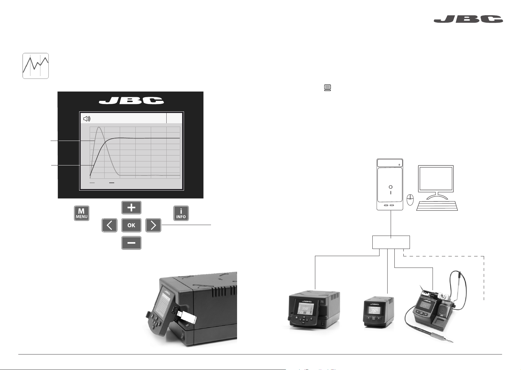
Manage and monitor the station using a Robotic system.
Working with Robots
Control
Unit
Robot
Update the station software
1. Download the JBC Update File from
www.jbctools.com/software.html and save
it on a USB flash drive. Preferably one with
no other files.
JBC
Update File
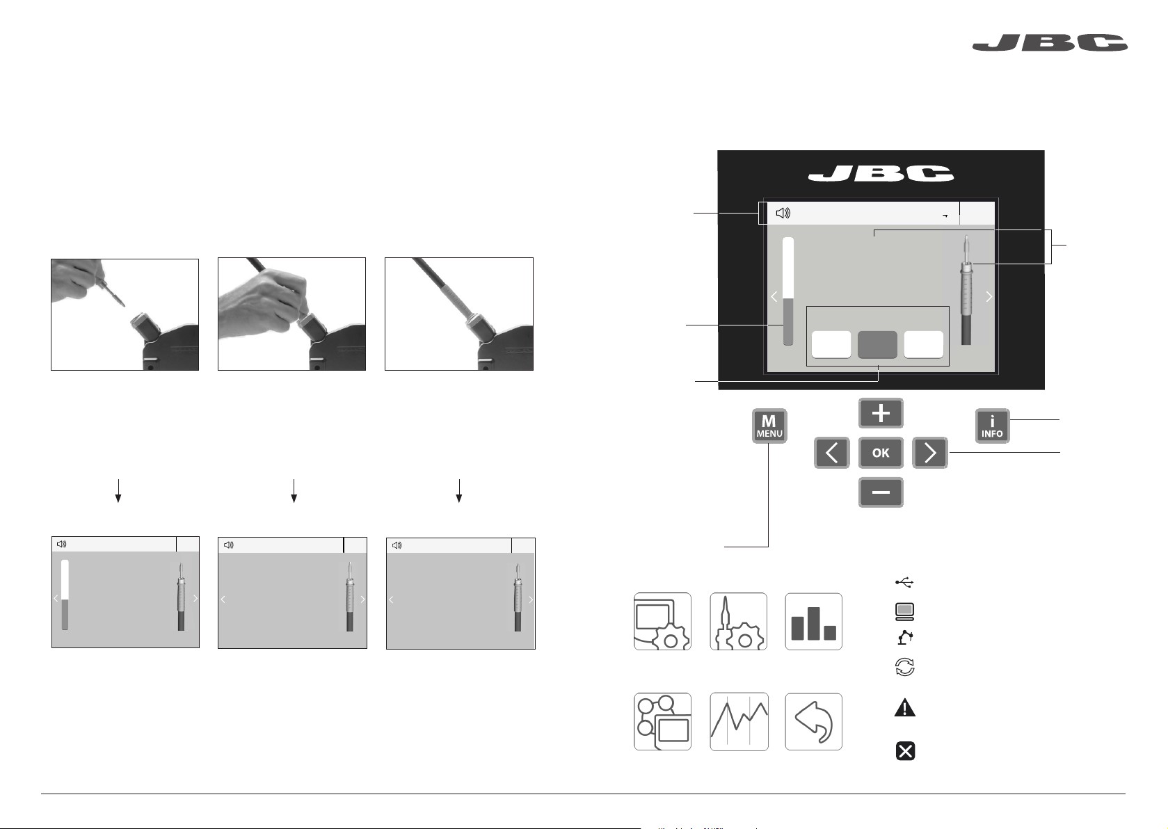
Before carrying out maintenance or storage, always allow the equipment to cool.
- Clean the station screen with a glass cleaner
or a damp cloth.
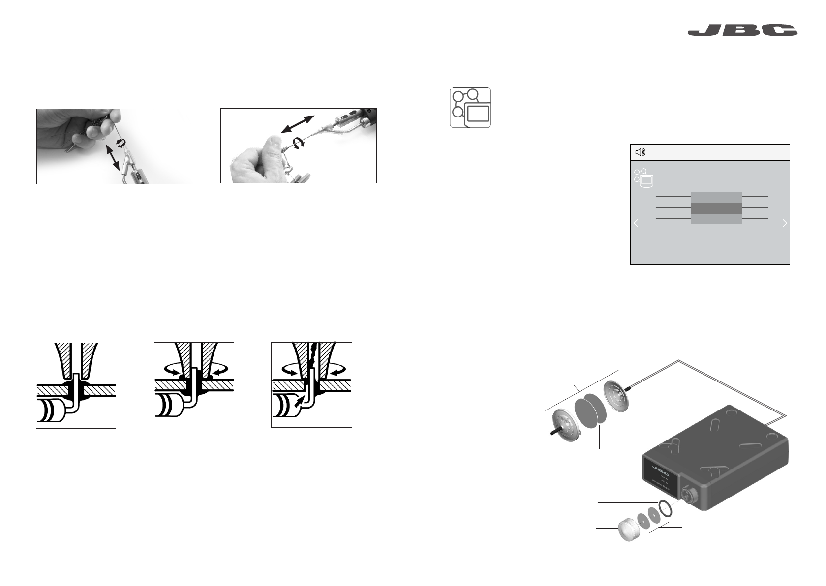
1. Pull off the fuse holder and remove the
fuse. If necessary use a tool to lever it off.
2. Press the new fuse into the fuse holder
and replace it in the station.
- Use a damp cloth to clean the casing and
the tool. Alcohol can only be used to clean
the metal parts.
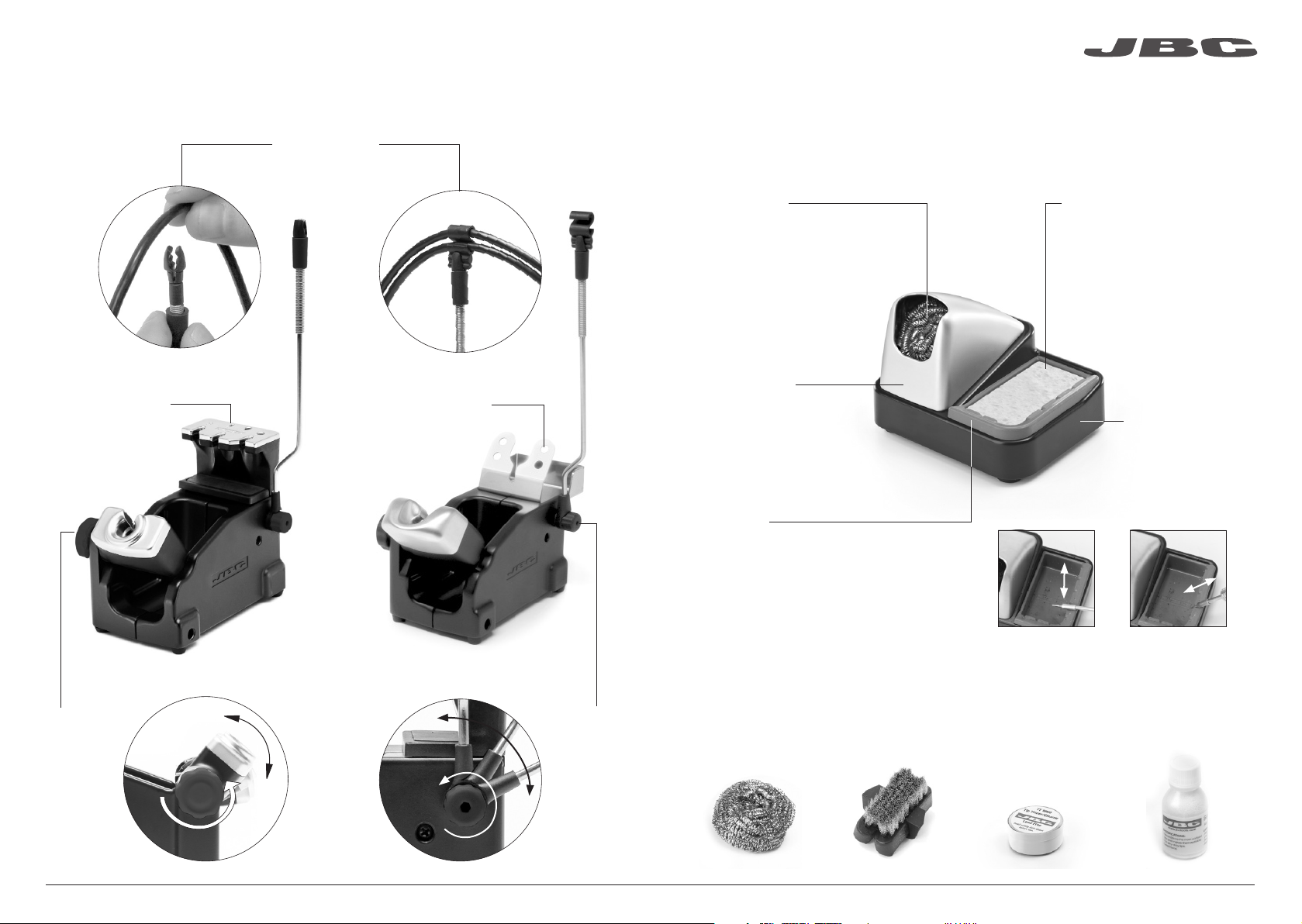
- Periodically check that the metal parts of
the tool and stand are clean so that the
station can detect the tool status.
Fuse holder
Fuse holder
- Maintain tip surface clean and tinned prior
to storage in order to avoid tip oxidation.
Rusty and dirty surfaces reduce heat
transfer to the solder joint.
- Periodically check all cables and tubes.
CHB-A
Converter
Ref. CHB-A
2. Insert the USB flash drive to the station.
The icon is diplayed while updating.
Fuse
RS-232
connection
- Replace a blown fuse as follows:
- Replace any defective or damaged pieces. Use original JBC spare parts only.
- Repairs should only be performed by a JBC authorized technical service.
18
www.jbctools.com
19

Safety
- Do not use the units for any purpose other than soldering or rework. Incorrect use may cause fire.
- The power cord must be plugged into approved bases. Be sure that it is properly grounded
before use. When unplugging it, hold the plug, not the wire.
- Do not work on electrically live parts.
- The tool should be placed in the stand when not in use in order to activate the sleep mode.
The soldering tip, the metal part of the tool and the stand may still be hot even when the station is
turned off. Handle with care, including when adjusting the stand position.
- Do not leave the appliance unattended when it is on.
- Do not cover the ventilation grills. Heat can cause inflamable products to ignite.
- Use a “non residue” classified flux and avoid contact with skin or eyes to prevent irritation.
- Be careful with the fumes produced when soldering.
- Keep your workplace clean and tidy. Wear appropriate protective glasses and gloves when
working to avoid personal harm.
- Utmost care must be taken with liquid tin waste which can cause burns.
- This appliance can be used by children over the age of eight and also persons with reduced
physical, sensory or mental capabilities or lack of experience provided that they have been given
adequate supervision or instruction concerning use of the appliance and understand the hazards
involved. Children must not play with the appliance.
- Maintenance must not be carried out by children unless supervised.
Specifications
Rework station with Electric Pump
DDSE-1B /DDSE-2B / DDSE-9B
- Total weight: 9.1 Kg (20 lb)
DDE-1B 120V 50/60Hz. Input fuse: 4A. Output: 23.5V
DDE-2B 230V 50/60Hz. Input fuse: 2A. Output: 23.5V
DDE-9B 100V 50/60Hz. Input fuse: 5A. Output: 23.5V
- Weight: 4.3 Kg (9.3 lb)
- Dimensions: 148 x 120 x 232 mm
- Output Peak Power: 150W per tool
- Temperature Range: 90-450°C (190-840 ºF)
- Idle Temp. Stability (still air) ±1.5 ºC (±3 ºF)
- Tip to ground resistance: <2 ohms
- Tip to ground voltage: <2mV RMS
- Ambient Operating Temperature: 10-40 ºC (50-104 ºF)
- USB-A / USB-B / Peripherals connectors
- RJ12 connector for Robot
MSE-A
- Weight: 1.2 Kg (2.6 lb)
- Dimensions: 145 x 55 x 225 mm
- Vacuum: 75% / 570 mmHg / 22.4 inHg
- Flow rate: 9 SLPM
Complies with CE standards
ESD protected housing “skin effect”
It is imperative to follow safety guidelines to prevent electric
shock, injury, fire or explosion.
20
www.jbctools.com
21

Premium Rework station
with Electric Pump
Ref. DDSE-B
Composición
Los siguientes artículos deberían estar incluidos:
Stand Cable
Cable del soporte .... 1 unidad
Ref. 0011283
Stand
Soporte ...... 1 ud
Ref. AD-SD
Sponge
Esponja ....................... 1 unidad
Ref. S0354
Metal Brush
Cepillo metálico ......... 1 unidad
Ref. CL6217
Manual ...................... 1 unidad
Ref. 0017355
Electric Desoldering Module
Módulo desoldador
eléctrico ....................... 1 unidad
Ref. MSE-A
Tip Cleaner
Limpiador
de puntas ..... 1 unidad
Ref. CL9885
Suction Filter
Filtro de aspiración .......... 1 ud
Ref. 0821830
Module Cable
Cable del módulo .... 1 unidad
Ref. 0014874
Cotton Filter
Filtros de algodón ... 1 unidad
Ref. 0781046
Contiene
10 filtros
Cleaning stick
Baqueta de limpieza ....... 1 ud
Ref. 0786640
DDE Control Unit
Unidad de Control DDE ... 1 unidad
Ref. DDE-1B (120V)
DDE-2B (230V)
DDE-9B (100V)
General Purpose Handle
Mango para aplicaciones
generales ............ 1 unidad
Ref. T245-A
Union Flanges
Bridas de unión ....... 1 unidad
Ref. 0011356
Contiene 2 bridas
Desoldering Iron
Desoldador ... 1 unidad
Ref. DR560-A
Stand
Soporte .. 1 u.
Ref. DR-SD
Cartridges
Cartuchos ............... 2 unidades
Ref. C245903
C245906
DR560 Accessories
Accesorios del DR560
Ref. 0010211
Internal joint Case
Casquillo junta
interior ................... 2 unidades
Ref. 0812360
Tip cleaning set
Juego de limpieza de puntas ............... 1 unidad
Ref. 0965970
Filter Box
Caja de filtros ....... 1 unidad
Ref. 0780840
Contiene
10 filtros
Spanner
Llave ........................... 1 unidad
Ref. 0780550
Tin deposit
Depósito de estaño ......... 1 ud
Ref. 0812620
Long Tip Cleaning set
Juego de limpieza de puntas largo .... 1 ud
Ref. 0965760
Metal tin diposit
Depósito de metal
para estaño ............ 1 unidad
Ref. 0812630
Filter Box
Caja de filtros ............ 1 unidad
Ref. 0005966
Contiene
50 filtros
Power cord
Cable de Red ............ 1 unidad
Ref. 0010569 (230V)
0013671 (100/120V)
Tips
Puntas ................. 3 unidades
Ref. C560005
Ref. C560013
Ref. C560004
22
www.jbctools.com
23
ww w. jbc to ols .c om

Conector USB-A
Pantalla color TFT de 2,8”
Incline la pantalla
para una mejor
lectura
Características
Trabaje simultáneamente con 2herramientas y enlace cada puerto con 1 módulo + 1 pedal (Peripherals).
Stand
Soporte
Ref. AD-SD
General Purpose
Handle
Mango para
aplicaciones generales
Ref. T245-A
Conector RJ12 para Robot
Conector USB-B
Conexión equipotencial
Toma de correinte
Desoldering Iron
Desoldador
Ref. DR560-A
Cartridge
Cartucho
Ref. C245903
Ref. C245906
Tip
Punta
Ref. C560004
Ref. C560005
Ref. C560013
Electric Desoldering Module
Módulo desoldador eléctrico
Ref. MSE-A
A otro periférico
Al Pedal
Ref. P-005
Stand
Soporte
Ref. DR-SD
Stand Cable
Cable del soporte
Ref. 0011283
Suction Filter
Filtro de succión
Ref. 0821830
Module Cable
Cable del módulo
Ref. 0014874
24
www.jbctools.com
25

Cambio rápido
de cartuchos
Cambie cartuchos
sin interrumpir
su trabajo
Soporte de
herramienta
ajustable
Se adapta a
su posición
de trabajo.
Recogecable
ajustable
Soportes ajustables
Stand
Soporte
Ref. DR-SD
Cambio rápido
de puntas
El sistema de
sujeción de puntas
facilita el cambio.
Recogecable
Mantiene el área de trabajo ordenada sin cable
Mejore la transferencia térmica de la punta limpiándola después de cada soldadura.
Limpiador de Puntas
Opcional
Brass wool
Lana de latón
Ref. CL6210
Inox wool
Lana inoxidable
Ref. CL6205
Brushes
Cepillos de metal
Ref. CL6220
Tip-tinner
Reestañador de puntas
Ref. TT-A
Sand · Arena
Ref. CL6211
Protección
anti-salpicaduras
Base antideslizante
Sponge
Esponja
Ref. S0354
Limpiador
Ref. CL0236
Método de limpieza muy
efectivo. Deja una fina capa
de soldadura en la punta para
prevenir la oxidación entre la
limpieza y la rehumectación.
Previene las salpicaduras
de partículas de
soldadura.
No es necesario
sujetar la base al
limpiar.
El método de limpieza más
eficaz y menos dañino.
Mantenga la esponja húmeda
con agua destilada, así evitará el
desgaste de la punta.
Receptáculo resistente a la temperatura
que permite al usuario eliminar el
exceso de soldadura golpeteando la
punta suavemente. Se puede extraer
fácilmente para su limpieza.
Golpeteo: Limpieza:
Golpee suavemente
para retirar el exceso
de soldadura.
Use las ranuras para
retirar las partículas
restantes.
Stand
Soporte
Ref. AD-SD
26
www.jbctools.com
27

ø 1
ø 1,5
ø 3,5
A
AB
A ø
Bø
C560-001 C560-002
C560-003
C560-004 C560-009
C560-014
B
C
A
D
Cambiar cartuchos del T245
1. Retirar 2. Insertar 3. Fijar
Coloque el soldador en el
extractor y tire para retirar
el cartucho.
Coloque el mango soldador
en la parte superior del
nuevo cartucho y presione
ligeramente.
Fije el cartucho* utilizando
los agujeros:
A. Para los C210 rectos.
B. Para los C210 curvados.
C. Para los C245 curvados.
D. Para los C245 rectos.
*Importante
Es necesario insertar el cartucho hasta la marca para una conexión correcta.
Marca
Cartuchos compatibles
El mango para soldador T245 funciona con cartuchos C245. Encuentre el modelo que mejor se
adapte a sus necesidades de soldadura en www.jbctools.com
Redondo Cincel Redondo
curvado Bisel Modelos
especiales
Ahorre tiempo cambiando los cartuchos de forma rápida y segura sin apagar la estación.
Cambiar puntas del DR560
Esta operación debe realizarse con la punta caliente (por encima de los 250°C) para que el estaño
de su interior se mantenga fundido.
250ºC mínimo
C560-001 ØA=1,4 ØB=0,6 Ømax. pin=0,4 C560-002 ØA=1,8 ØB=0,8 Ømax. pin=0,6
C560-003 ØA=2,7 ØB=1 Ømax. pin=0,8
C560-004 ØA=3,2 ØB=1,3 Ømax. pin=1,1 C560-009 ØA=5 ØB=1,3 Ømax. pin=1,1
C560-014 ØA=2,5 ØB=0,8 Ømax. pin=0,6
1. Retirar
Desenrosque la punta utilizando la llave
suministrada.
2. Insertar
Coloque la punta nueva y enrósquela
con la llave para asegurarse que queda
hermético.
Puntas compatibles
El DR560 funciona con puntas C560.
Encuentre el modelo que mejor se adapte a sus necesidades de desoldadura en www.jbctools.com
Algunas de las puntas
C560 en tamaño real
(mm):
28
www.jbctools.com
29

Cambiar el elemento calefactor del DR560
1. Desenroscar
Desenrosque la tapa del
depósito.
2. Retirar
Afloje el tornillo y retire el
elemento calefactor.
3. Colocar
Coloque el nuevo elemento
calefactor hasta la marca* y
siga los mismos pasos a la
inversa.
2
1
3
Para realizar esta operación apague la estación o desconecte la herramienta.
Limpieza del depósito de estaño del DR560
1. Retirar la tapa
3. Insertar el depósito
Compruebe
el filtro
Tapa
Compruebe la
junta interna
2. Limpiar
El filtro y la junta interna deben supervisarse
para reemplazarlos si fuera necesario, ya sea
por exceso de suciedad o por algún daño.
Retire el espiral para limpiar el interior del
depósito con la baqueta suministrada.
La tapa se debe retirar con el desoldador en
posición vertical.
El depósito se debe insertar con el espiral ya
colocado entre las dos marcas.
Concluya el proceso cerrando el depósito
con la tapa.
*Importante
Para una conexión apropiada es necesario insertar el cartucho alineándolo con la marca .
Marcas
30
www.jbctools.com
31

Peripherals Port 2-DR
17:14
Pedal None
Module None
Module
MSE_a
None
Cambiar los filtros de la bomba MSE
- Limpie la carcasa con un paño húmedo. Asegúrese que utiliza un paño suave para el frontal.
- Revise periódicamente los cables y tubos.
- Mantenga los filtros limpios para garantizar una correcta aspiración y reemplácelos si fuera necesario.
Filtros
Ref. 0005966
Suction filter
Filtro de aspiración
Ref. 0821830
Anillo
Ref. 0007717
Tapa de filtros
Ref. 0004710
Proceso de desoldadura
La punta elegida debe tener un diámetro más grande que el pad para conseguir la máxima aspiración
posible y el mejor rendimiento térmico.
Coloque la punta en el
terminal del through-hole
tal y como se muestra.
Tras pulsar el botón del desoldador hay un ligero retraso hasta que la bomba de succión se
detiene. Esto asegura que el conducto de succión está completamente vacío.
Si se quedaran restos de soldadura en algun terminal después de desoldarlo, vuelva a soldarlo
con estaño nuevo y repita el proceso de desoldadura.
Cuando la soldadura se liqüe,
gire la punta con suavidad
para que el terminal del
componente se suelte.
Pulse el botón de la bomba
de succión hasta retirar
por completo los restos de
soldadura.
3. Aspirar1. Colocar 2. Rotar
Importante
No utilice objetos
punzantes para
abrir el filtro de
aspiración.
El conducto de entrada se debe limpiar periódicamente con la baqueta más grande posible.
Mantenimiento de puntas del DR560
Importante
NO pulse el botón de la bomba de succión mientras estaña la punta, ya que los humos produ-
cidos por el flux bloquearían rápidamente los conductos y el filtro de aire.
1. Seleccione el módulo del listado de
conexiones periféricas. Recuerde que su
primera conexión se indica como “a”, la
segunda como “b”, etc. (MSE_a, MSE_b,...)
2. Pulse Menu o Back para guardar los
cambios. Una vez configurado podrá
modificar cambios desde el menú Peripherals.
Puesta en marcha de la bomba MSE
Peripherals
Tras conectar el módulo desoldador eléctrico (MSE-A), entre en el menú de
Peripherals y seleccione el puerto con el que desee enlazar el módulo.
Cotton filters
Filtros de algodón
Ref. 0781046
32
www.jbctools.com
33

350ºC
Port
2
Power
45%
Temp. Levels
T245
250 350 380
17:14
Port
2
T245
17:14
350ºC
Port
2
Power
45%
T245
17:14
Selected 350ºC
Sleep
Tool in the stand
Actual Temp. 180ºC
Delay to hibernation: 29:30
Port
2
T245
17:14
Hibernation
Actual Temp. 25ºC
Station Tools Counters
ResetGraphicsPeripherals
3. Hibernación
Funcionamiento
El exclusivo sistema calefactor de JBC
Nuestra tecnología revolucionaria es capaz de recuperar la temperatura de la punta de forma
extremadamente rápida. Esto significa que el usuario puede trabajar a una temperatura más baja
y mejorar la calidad de la soldadura. Esta temperatura se reduce aún más gracias a los modos de
Sleep e Hibernation que incrementan hasta 5 veces la vida de las puntas.
1. Trabajo 2. Sleep
Al levantar la herramienta
del soporte, la punta se
calienta hasta la temperatura
seleccionada.
Si la herramienta permenece
en el soporte, la temperatura
se reduce a la temperatura
predefinida.
Tras largos períodos de
inactividad (predefinido a
30min), se corta el suministro
de energía y la punta se enfría
hasta temperatura ambiente.
Menú Tools:
· Configure la temperatura
de Sleep
· Configure el tiempo de
retraso de Sleep
(de 0 a 9 min o ninguno)
· Configure el retraso de
Hibernación
(de 0 a 60 min o ninguno)
Menú Tools: Menú Tools:
Períodos
largos en el
soporte
· Configure límites de
temperatura.
· Seleccione niveles de
temperatura.
Unidad de memoria USB conectada.
Estación controlada por un PC.
Estación controlada por un robot.
Actualización del software de la estación.
Pulse INFO para iniciar el proceso.
Aviso.
Pulse INFO para la descripción del fallo.
Error. Pulse INFO para la descripción del
fallo, el tipo de error y cómo proceder.
Notificaciones (Barra de estado)
Ayuda de la
estación
Indicador de
potencia
Herramienta
en uso
Pantalla de trabajo
Barra de
estado
La DDE-B presenta una interfaz de usuario intuitiva y ofrece un rápido acceso a los parámetros.
Cambio de
puerto
Se muestra si
los niveles de
temperatura
están activos
Pulse INFO para la descripción de parámetros.
Opciones de Menú
34
www.jbctools.com
35

Port 1 - T245
450
400
350
300
250
150
100
50
200
Power Temp
17:14
Graphics
Pulsando sobre Graphics en el menú principal, se muestran las respuestas de
temperatura y potencia en tiempo real de cada puerto. Esto le ayudará a decidir
cuál es la punta más adecuada para obtener la mejor calidad en sus soldaduras.
Análisis del proceso
Exporte gráficos
Inserte una unidad de memoria USB para
guardar su proceso de trabajo en formato csv.
Temperatura
Potencia (%)
Vea el gráfico
del otro puerto
Red de soldadura
Gestione y monitorice tantas estaciones como soporte su PC.
Funciones:
- Configure todos los parámetros de la estación desde su PC.
- Organice grupos de estaciones y configure todos sus parámetros al mismo tiempo.
- Guarde configuraciones específicas para usos posteriores.
- Analice gráficos del proceso de soldadura de las estaciones desde su PC y expórtelos.
cualquier
estación
JBC
JBC
Manager
software
USB Hub
1. Descargue el software JBC Manager y el manual de usuario de www.jbctools.com/manager.html
2. Conecte las estaciones a través del conector USB-B y el PC las detectará automáticamente.
3. La notificación se mostrará en la estación.
36
www.jbctools.com
37

Mantenga limpio
1. Conecte la herramienta a la estación utilizando el convertidor CHB-A (Ref: CHB-A).
2. Conecte su sistema robotizado al conector Robot de la estación (RJ12).
Si lo necesita, el adaptador DB9-RJ12 está disponible (Ref: 0013772).
3. Active la opción de robot en la estación y se mostrará la siguiente notificación:
4. Configure su sistema robotizado según el Protocolo de Comunicación para Robots,
que encontrará en www.jbctools.com/jbcsoftware-menu-115.html.
Gestione y monitorice la estación por medio de un sistema robotizado.
Trabajar con Robots
Unidad
de Control
Robot
Actualice el software de la estación
1. Descargue el archivo de actualización de
www.jbctools.com/software.html
cuando esté disponible y guárdelo en una
unidad de memoria USB (preferentemente
una sin otros archivos).
JBC
Update File
Convertidor
CHB-A
Ref. CHB-A
Conexión
RS-232
Mantenimiento
Antes de realizar tareas de mantenimiento o almacenar, desconecte el equipo y déjelo enfriar.
1. Tire del portafusible para retirar el fusible.
Si lo precisa, utilice una pequeña palanca.
2. Sustituya el fusible y coloque de nuevo el
portafusibles en su sitio.
- Use un paño húmedo para limpiar la
pantalla del equipo, la carcasa y la
herramienta. Puede utilizar alcohol
solamente en las partes metálicas.
- Compruebe periódicamente que las partes
metálicas de la herramienta y del soporte
están limpias. Así la estación puede
detectar el estado de la herramienta y
activar los modos de Sleep o Hibernation.
Portafusible
Portafusible
- Mantenga la punta limpia y estañada la
para evitar su oxidación. Las superfícies
sucias reducen la transferencia térmica a la
soldadura.
- Revise periódicamente los tubos y cables.
Fusible
2. Inserte la unidad de memoria USB.
La notificación se muestra mientras
se actualiza el software.
- Cambie el fusible fundido de la siguiente manera:
- Cambie cualquier pieza defectuosa o dañada. Utilice solamente recambios originales de JBC.
- Cualquier reparación sólo se podrá realizar por un servicio técnico oficial JBC.
38
www.jbctools.com
39
This manual suits for next models
3
Table of contents
Languages:
Other jbc Rework Station manuals