jbc RMVE-B User manual

Premium
Complete Rework station
with Pneumatic Pump
Ref. RMVE-B
Español 35
English 3
Page
www.jbctools.com

2 3
Index
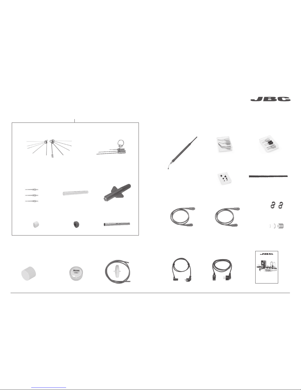
Packing list ...........................................................4
JT Hot Air station
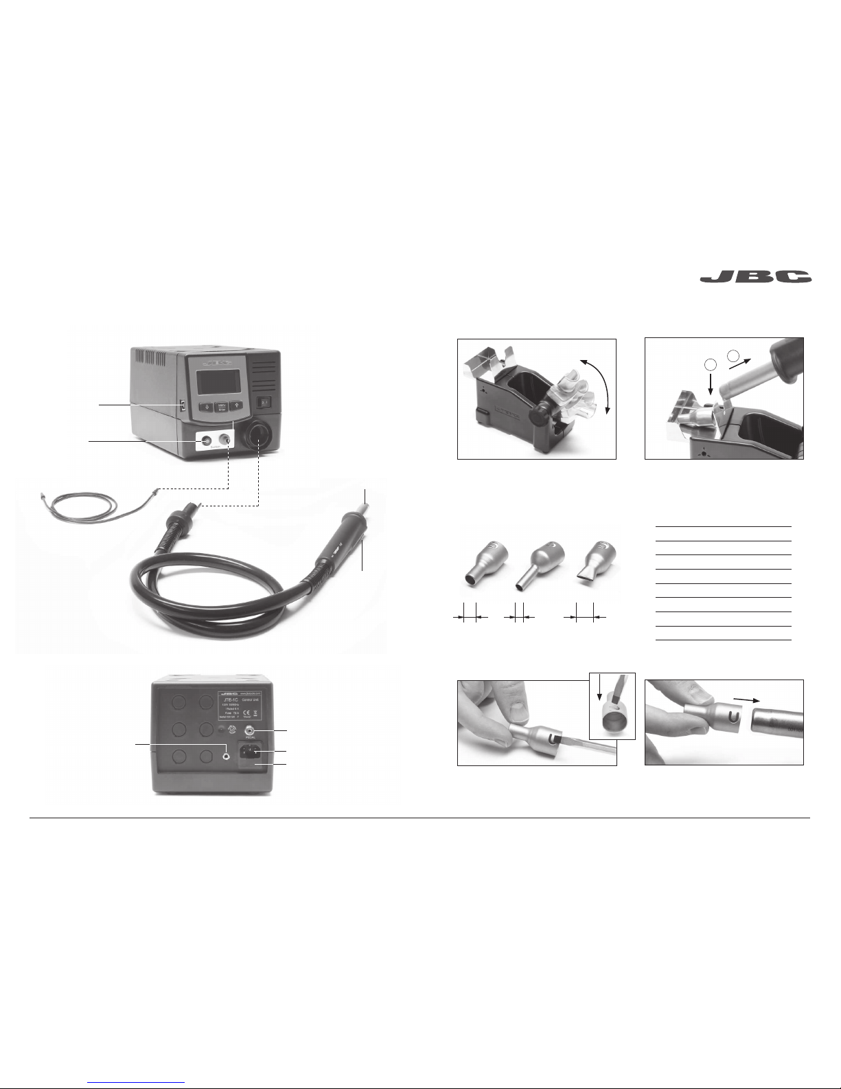
Features .............................................................. 8
Stand & Nozzle changer ................................ 9
Protectors & Extractors ................................10
T260 Pick & Place ..........................................11
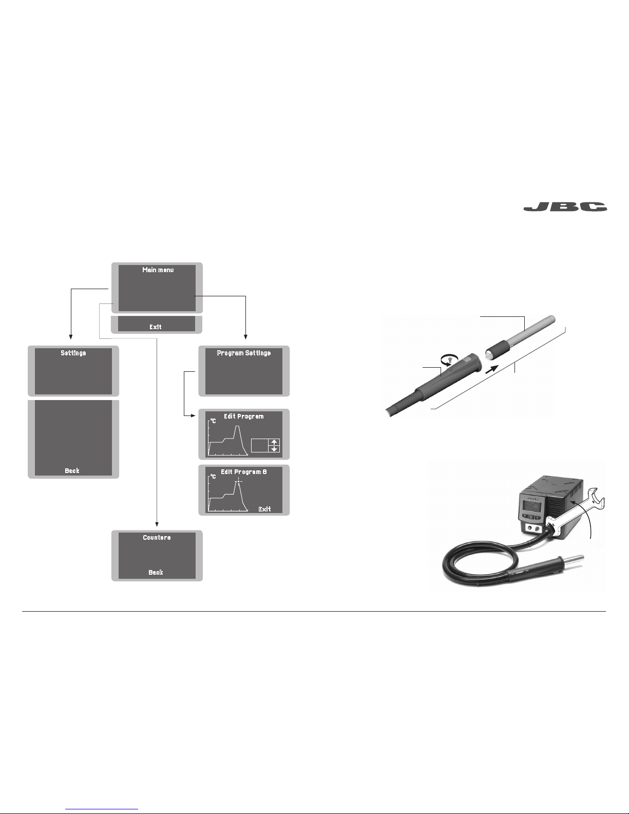
Operation & Process Control with JT .......12
JT-TA Replacing the Heating Element ......15
JT-TA Changing the Heater Hose Set ...... 15
DDE Control Unit & MVE Module
Features ............................................................16
Stands & Tip Cleaner ....................................18
T245 Changing Cartridges ..........................20
DR560 Changing Tips .................................. 21
DR560 Changing the Heating Element ... 22
DR560 Tin Deposit Cleaning ...................... 23
DR560 Tip Care ..............................................24
Desoldering Process DDE & MVE .............24
MVE Initial Setup ............................................25
MVE Changing the pump filters .................25
Operation with DDE ...................................... 26
Process Analysis ............................................28
Soldering Net .................................................. 29
Working with robots ......................................30
Station Sotware ..............................................30
Maintenance ..................................................... 31
Safety ...................................................................32
Specifications .................................................. 33
Exploded View ................................................. 66
www.jbctools.com

4 5
Packing List
The following items should be included:
Stand .................................1 unit
Ref. AD-SD
Pneumatic Desoldering
Module..............................1 unit
Ref. MVE-A
DDE Control Unit ............1 unit
Ref. DDE-1B (120V)
DDE-2B (230V)
DDE-9B (100V)
Desoldering Iron............ 1 unit
Ref. DR560-A
Stand .................................1 unit
Ref. DR-SD
Soft Thermal Insulator
Handle ................................1 unit
Ref. T245-C
Heater hose set ............1 unit
Ref. JT-T1A (100V / 120V)
JT-T2A (230V)
Stand ..................................1 unit
Ref. JT-SB
JTE Control Unit ............1 unit
Ref. JTE-1C (120V)
JTE-2C (230V)
JTE-9C (100V)
Tip Cleaner........................1 unit
Ref. CL9885
JT Accessory set
Ref. 0012332
Sponge ...............................1 unit
Ref. S0354
Metal Brush ......................1 unit
Ref. CL6217
Cartridges.......................2 units
Ref. C245903 (x1)
Ref. C245906 (x1)
* These accessories are not supplied with JT-2QC / JT-1QC / JT-9QC stations.
Extractor stand* ..............1 unit
Ref. 0008752
Suction Tube*
Ref. 0932330
Suction Cups*
Ref. 0930110
Ø 10 - 0934050 (x3)
Ø 4.7 - 0934070 (x1)
Extractors*
Ref. E2184
E2064
E2052
Protectors*
Ref. P2220
P2230
P2235
P4000
P4010
Tripod*
Ref. T2050 (Ø 39mm)
T2250 (Ø 85mm)
Nozzles
Ref. JN2015 (x1)
JN2012 (x1)
JN2020 (x1)
www.jbctools.com

6 7
Suction Filter ................1 unit
Ref. 0821830
Cotton Filter ..................1 unit
Ref. 0781046
It contains 10 filters
Filter Box .........................1 unit
Ref. 0005966
It contains 50 filters
DR560 Accessories
Ref. 0010211
Internal joint Case........2 units
Ref. 0812360
Tip cleaning set ..........................................1 unit
Ref. 0965970
Spanner ...........................1 unit
Ref. 0780550
Tin deposit ......................1 unit
Ref. 0812620
Long Tip Cleaning set ............................1 unit
Ref. 0965760
Metal tin diposit ............1 unit
Ref. 0812630
Tips ..............................3 units
Ref. C560005
Ref. C560013
Ref. C560004
Manual ...............................1 unit
Ref. 0016198
Premium
Complete Rework station with
Pneumatic Pump
Ref. RMVE-B
Stand Cable...................2 units
Ref. 0011283
Power cords
For DDE ........................... 1 unit
Ref. 0013671 (100/120V)
0010569 (230V)
Module Cable ...................1 unit
Ref. 0014874
Cleaning stick ................1 unit
Ref. 0786640
Pick & Place......................1 unit
Ref. T260-A
Straight Needles Set......1 unit
Ref. 0901546
Bent Needles Set............1 unit
Ref. 0861660
Cups Set............................1 unit
Ref. 0940163
Union Flanges .................1 unit
Ref. 0011356
Filter Box ......................1 unit
Ref. 0780840
It contains
10 filters
Escape Filter ...................1 unit
Ref. 0008446
For JTE.........................1unit
Ref. 0009417 (100V/120V)
0009401 (230V)
www.jbctools.com
ww w.j bc to ol s.c om

JT Features
8 9
Compatible Nozzles
The JT-TA works with JT nozzles. Find the model that best suits your soldering needs in www.jbctools.com
2
1
Heating
element
Suction Tube
Ref. 0932330
Heater Hose set
Ref. JT-T1A (100V - 120V)
JT-T2A (230V)
For tripods
and extractors
Activation of
suction pump
USB-B connector
Update the station
software from
the JBC website
Hot Air switch
(ON / OFF)
Other connectable tools:
Precision Heater hose set
Ref: TE-TB
Power Socket
Fuse
Equipotential
connection
To Pedal
Ref. P-005
Press the pedal to start
hot air or release to stop.
In case of loosely fitting nozzle:
Ref. Shape Size
JN2020 Straight Ø 8mm
JN8417 Straight Ø 10mm
JN2015 Bent Ø 4mm
JN2012 Bent Ø 6mm
JN6633 Bent Ø 8mm
JN7637 Flat 10 x 2mm
JN7638 Flat 20 x 2mm
JN7639 Flat 30 x 2mm
Straight Bent Flat
Ø mm Ø mm A x B mm
Suits your work position
Adjustable Stand with Nozzle changer
1. Push the nozzle tab inwards with a
screwdriver or flat-nosed pliers.
2. Insert the nozzle into the JT-TA Heater again.
Nozzle changer
www.jbctools.com

Choose the suction cup that best fits the component (Maximum working temp.: 250ºC / 482ºF):
10 11
For small components (fig. 1 and 2). For big components (fig. 3 and 4).
1. Suction 2. Release
This tool helps you easily place and remove SMDs of any size using the suction provided by the station.
T260 Pick & Place
Press the button to
start/stop the suction
Once activated
the suction button,
cover the pen hole
with your finger and
pick the component.
Insert the needle
with the appropriate
cup for a correct
suction process.
Lift your finger
to release the
component on the
appropriate place.
You should avoid the
needle to stick out of
the lower part.
We recommend using the protector + tripod We recommend using the extractors
Protectors & Extractors
1 2 3 4
Protectors
* Ref. AxB (mm) * Ref. AxB (mm)
P3353 4,3 x 3 48 P2230 15 x 15
P3786 5,2 x 5,2 60 P4010 17 x 17
P3352 5,2 x 7,5 P4005 18 x 29
P3355 5,2 x 9,5 P4030 18,5 x 18,5
P3356 6,2 x 4,2 P1068 18,5 x 24
P3785 7,2 x 7,2 P2685 28,5 x 28,5
P3784 8,2 x 8,2 P4085 31,5 x 31,5
P4035 9 x 13 P2672 33 x 46
P4040 9,5 x 19 P4002 50 x 50
P4080 9,5 x 21 P3357 52,5 x 14
32 P2220 10 x 10
P4045 10,5 x 21
P4090 11 x 16
24 P2235 12 x 17
P1249 12 x 23
44 P4000 12,5 x 12,5
P3354 13,2 x 13,2
P4025 13,5 x 21,5
øD
* Reference Desk
Tripods
* Ref. øC (mm)
T2050 39
T2250 85
Manual extractor
* Ref. øD (mm)
E2190 7
Extractors
* Ref. AxB (mm) * Ref. AxB (mm)
52 E2052 20 X 20 E2124 45 X 45
64 E2064 20 X 26
80 E2184 24 X 24
E2068 27 X 27
E4020 28,5 X 28,5
E4015 31,5 X 31,5
E2084 33 X 33
E2100 38 X 38
Operation
Pick & Place
Ref. T260-A
Tripod
Tripod
Protector
Protector
www.jbctools.com

Temp
º
CAir %
Time to stop 45 seconds
Power 70%
400 85
400ºC Select
Temp
º
C
º
CProgram 8
380
Air 100%
Time 125s.
12 13
Operation with JT station
Process Control
3. Releasing1. Placing 2. Heating
Position the suction cup. Push the button for hot air
heating. The solder melts.
The component lifts off
automatically.
Access Menu (pess key 2 seconds) & Confirm Selection
Selected temperature
Current temperature
% Instant power supplied
to heater
You can switch between operating modes (Manual Mode / Profile Mode) by pressing the “increa-
se” and “decrease” keys simultaneously for 2 seconds. (Only when mode profiles is ON)
Manual mode
Decrease program
number
Increase program
number
Selected program
Current temperature
Selected flow
Graph of selected
program
Remaining time
Program mode
Program Options
Edit Program
This option allows you to edit or create a program.
First , you must select the program to edit and then modify the points that make up the program.
Each program is composed of 9 points, each point consisting of 3 parameters:
1. Time (seconds)
2. Temperature (°C / °F)
3. Flow rate (%)
You can delete the last point of the program by selecting “-----” in the time parameter.
It should be taken into account that the regulation range permitted by the station is 150-450°C,
whereby it is not possible to create temperature ramps between room temperature (Toff) and
150°C.
The station can store up to 25 temperature programs.
The first three programs are edited by JBC as an example.
Copy Program
This option allows you to copy a program.
You must select the program source and the program destination (where it will be copied).
Delete Program
This option will allow you to delete a previously selected program.
www.jbctools.com

Main menu
1 Reset settings
2 Station
Settings
3
Program Settings
4
Counters
5 Program version
Exit
Settings Program Settings
Edit Program
Edit Program 8
1
Temp unit Celsius
2 Maximum
temp 450
0
C
3Minimum temp T OFF*
4 Fix temp 400
0
C
5 Temp Adjust 0
0
C
6 Max air 100%
7 Min air 10%
8 Fix air 40%
9 Time to stop 120 sec
10 Beep ON
11 Pop up ON
12 Change PIN
1 Programs
2 Edit program
3
Copy program
4
Delete program
Back
Select
Program
Step 4
Time 20
Temp 450
Air 100
º
C
º
C
8
Exit
Counters
1 Station ON hours
0
2
Works hours 0
3Works
cycles 0
Back
14 15
* Selecting Minimum Temp to
“T OFF” allows for blowing at
ambient temperature.
Menu screen
Original PIN: 0105
Only perform this operation when the element is cold and the unit is disconnected from the mains.
1. Loosen the screw.
2. Pull the heating element away from the handle.
3. Connect the new heating element, ensuring its pushed all the way in.
4. Tighten the screw.
JT-TA Replacing the Heating Element
Heating Hose Set
Ref. JT-T1A (100V / 120V)
JT-T2A (230V)
Heating Element
Ref. 0014107 (230V)
0014105 (100V / 120V)
Handle
Ref. 0009829
1. Ensure that the tool is turned off.
2. Use a spanner to unscrew the connecting nut.
3. The tube end of the new heater must be inserted
so that the longitudinal rib fits into the groove.
5. Follow the same steps conversely.
JT-TA Changing the Heater Hose Set
www.jbctools.com

DDE & MVE Features
Work simultaneously with up to 2 tools and join each station port with 1 module + 1 pedal (Peripherals).
Stand
Ref. AD-SD
Soft Thermal
Insulator
Handle
Ref. T245-C
RJ12 connector for Robot
USB-B connector
Equipotential connection
Power Socket
Desoldering Iron
Ref. DR560-A
Cartridge
Ref. C245903
Ref. C245906
Tip
Ref. C560004
Ref. C560005
Ref. C560013
Pneumatic Desoldering Module
Ref. MVE-A
16 17
Stand
Ref. DR-SD
Stand Cable
Ref. 0011283
Suction Filter
Ref. 0821830
Module Cable
Ref. 0014874
USB-A
connector
2,8” Color TFT screen
Tilt the display for
easy reading
To another
module
To Pedal
Ref. P-005
Air pressure
(4-6 bar)
www.jbctools.com

Stand
Ref. AD-SD
18 19
Quick tip changer
Permits switching
cartridges without
interrupting
your work.
Adjustable
tool holder
Suits your
work
position.
Adjustable
cable
collector
Adjustable Stands
Stand
Ref. DR-SD
Quick tip changer
Holding tip system
for easy change.
Cable collector
Keeps working area free of cable.
It can be easily
removed for
cleaning.
Improve thermal transfer by cleaning the tip after each solder joint.
Tip Cleaner
Brass wool
Ref. CL6210
Splashguard Wiper tray
Ref. CL0236
Very effective cleaning
method. It leaves a small
layer of solder on the
tip to prevent oxidation
between cleaning and
rewetting.
It prevents splashing of
solder particles. Also used
for sponge or brushes.
for Sponge: for Brushes: Tapping: Wiping: Maintenance
Tap to remove
excess solder.
Use the slots to
remove remaining
particles.
Non-slip base
Sponge
Ref. S0354
No need to hold the
base while cleaning tips.
The least harmful
cleaning method. Keep
the sponge damp with
distilled water when
working to avoid tip wear.
A temperature resistant receptacle lets the operator
remove excess solder by gentle tapping or wiping.
Optional
Inox wool
Ref. CL6205
Brushes
Ref. CL6220
Tip-tinner
Ref. TT-A
Sand
Ref. CL6211
www.jbctools.com

ø 1
ø 1,5
ø 3,5
A
AB
A ø
Bø
20 21
T245 Changing Cartridges
1. Removing 2. Inserting 3. Fixing
Place the handle in the
extractor and pull to
remove the cartridge.
Place the handle on top of
the new cartridge and press
down slightly.
Use the holes for fixing the
cartridge* as follows:
A. For straight C210.
B. For curved C210.
C. For curved C245.
D. For straight C245.
*Important
It is essential to insert the cartridges as far as the mark for a proper connection.
B
C
A
D
Compatible cartridges
The T245 handle works with C245 cartridges. Find the model that best suits your soldering needs
in www.jbctools.com
Round Chisel Round bent Bevel Special models
Save time and change cartridges safely without switching the station off.
DR560 Changing Tips
This operation should be done while the tip is hot, not below 250°C, so that any tin left inside is in
molten state.
250ºC minimum
C560-001 C560-002
C560-003
C560-004 C560-009
C560-014
C560-001 ØA=1,4 ØB=0,6 Ømax. pin=0,4 C560-002 ØA=1,8 ØB=0,8 Ømax. pin=0,6
C560-003 ØA=2,7 ØB=1 Ømax. pin=0,8
C560-004 ØA=3,2 ØB=1,3 Ømax. pin=1,1 C560-009 ØA=5 ØB=1,3 Ømax. pin=1,1
C560-014 ØA=2,5 ØB=0,8 Ømax. pin=0,6
1. Removing
Unscrew the tip using the spanner
supplied.
2. Inserting
Fit the new tip and tighten with the
spanner to make sure it is air tight.
Compatible Tips
The DR560 works with C560 tips. Find the model that best suits your soldering needs in www.jbctools.com
Here are some C560 tips in real size (in mm):
Mark
www.jbctools.com

22 23
DR560 Changing the Heating Element
1. Loosening
The deposit lid needs to be
loosened.
2. Removing
Loosen the screw as shown
and remove the
Heating Element.
3. Placing
Place the new Heating
Element and follow the steps
conversely.
2
1
3
To perform this operation, turn off the station or disconnect the tool.
Important
For a proper connection it is essential to insert the cartridge by lining it up to the mark .
DR560 Tin Deposit Cleaning
1. Removing the lid
3. Inserting the deposit
Check filter
Lid
Check
internal joint
2. Cleaning
The filter and internal joint must be checked
and replaced if dirty or damaged.
Remove the coil to clean the inside of the
deposit with the stick supplied.
The lid must be removed with the DR560 in
vertical position.
The deposit must be inserted with coil filter in
place, positioned between the 2 lines marked
on the tin deposit.
Then the whole unit must be closed by
screwing the lid.
Marks
www.jbctools.com

24 25
MVE Changing the pump filters
- Clean the casing with a damp cloth. Make sure to use a soft cloth when cleaning the front.
- Periodically check all cable and tube connections.
- Keep filters clean to ensure proper solder suction and replace them when necessary.
Desoldering process
Use a tip with a larger diameter than the pad to achieve maximum aspiration and thermal efficiency.
Place the tip with the
component terminal in the
hole.
After pressing the desoldering key there is a slight delay until the self-contained vacuum pump
stops. This makes sure that the vacuum circuit is completely empty. If any solder remains are left
on a terminal after desoldering it, resolder it with fresh solder and repeat the desoldering operation.
When the solder liquefies,
gently rotate the tip so that
the component terminal can
be lifted off.
Press the vacuum pump
button long enough to remove
the solder.
3. Aspirating1. Placing 2. Rotating
The intake tube should be periodically cleaned by the largest rod.
DR560 Tip Care
Important
DO NOT press the vacuum pump button while tinning the desoldering tip, as the fumes given
off by the flux would quickly block the ducts and the air filter.
1. Select the module from the list of
peripheral connections. Remember your first
connection is denoted as “a”, the second
being “b”, etc. (e.g. MVE_a, MVE_b,...)
2. Press Menu or Back to save changes.
Once set up, you can change the module
settings by entering the Peripherals Menu.
MVE Initial Setup
Peripherals
After connecting the electric desoldering module (MVE-A), enter the Peripherals
Menu and select the port which you want to join with the module.
MVE Changing the pump filters
Important
Do not use sharp
pointed objects
to open the
suction filter.
Spare filters
Ref. 0005966
Cotton filters
Ref. 0781046
Suction filter
Ref. 0821830
O Ring
Ref. 0007717
Filter cover
Ref. 0004710
Escape filter
Ref. 0008446
Peripherals Port 2-DR
17:14
Pedal None
Module None
Module
MVE_a
None
www.jbctools.com

350ºC
Port
2
Power
45%
Temp. Levels
T245
250 350 380
17:14
26 27
Port
2
T245
17:14
3. Hibernation
Operation
The JBC Exclusive Heating System
Our revolutionary technology is able to recover tip temperature extremely quickly. It means the user
can work at a lower temperature and improve the quality of soldering. The tip temperature is further
reduced thanks to the Sleep and Hibernation modes which increase the tip life by 5.
1. Work 2. Sleep
When the tool is lifted from the
stand the tip will heat up to the
selected temperature.
When the tool is in the stand,
the temperature falls to
180ºC / 360ºF (preset sleep
temperature).
After longer periods of
inactivity (pre-set to 30 min.),
the power is cut off and the
tool cools down to room
temperature.
Tools Menu:
· Set Sleep temperature
· Set Sleep delay
(from 0 to 9 min or no Sleep)
· Set Hibernation delay
(from 0 to 60 min or no
hibernation)
Tools Menu: Tools Menu:
Long time in
the stand
· Set temperature limits
· Select temperature levels
350ºC
Port
2
Power
45%
T245
17:14
Selected 350ºC
Sleep
Tool in the stand
Actual Temp. 180ºC
Delay to hibernation: 29:30
Port
2
T245
17:14
Hibernation
Actual Temp. 25ºC
USB flash drive is connected.
Station is controlled by a PC.
Station is controlled by a robot.
Station software update.
Press INFO to start the process.
Warning.
Press INFO for failure description.
Error. Press INFO for failure description,
the type of error and how to proceed.
System notifications (Status Bar)Menu Options
Station
Information
Power
indicator
Tool
in use
Work Screen
Status bar
The DDE offers an intuitive user interface which provides quick access to station parameters.
Change
port
Displayed if
temperature
levels are
activated
Station Tools Counters
ResetGraphicsPeripherals
Press INFO for each parameter description.
www.jbctools.com

Port 1 - T245
450
400
350
300
250
150
100
50
200
Power Temp
17:14
28 29
By pressing Graphics in the main MENU, temperature and power figures in real
time are displayed for each port. This helps you decide which tip to use to obtain
the best quality solder joints.
Process analysis
Export graphics
Insert a USB flash drive into the USB-A
connector to start saving your soldering
process in csv format.
Graphics
Temperature
Power (%)
See other
port graphic
Soldering Net
Remotely manage and monitor as many stations as your PC can handle.
Functions:
- Set all the station parameters from your PC.
- Organize groups of stations and set all their parameters at the same time.
- Store specific configurations for later uses.
- Analyze the soldering graphics of the stations on your PC and export them.
1. Download the JBC Manager software and the user manual from www.jbctools.com/manager.html
2. Connect the stations via USB-B connector and the PC will automatically detect them.
3. The notification will be displayed on the station.
any JBC
station
JBC
Manager
software
USB Hub
www.jbctools.com

30 31
Clean periodically
Maintenance
1. Connect the tool to the station port by means of the Converter.
2. Connect your Robot system to the Robot connector (RJ12) of the station.
DB9-RJ12 Adapater available only if necessary (Ref: 0013772).
3. Enable the Robot option in the station settings and the notification will be displayed:
4. Set your Robot’s commands according to the Robot Communication Protocol, available on the
website www.jbctools.com/jbcsoftware-menu-115.html.
Manage and monitor the station using a Robotic system.
Working with Robots
Control
Unit
Robot
Update the station software
1. Download the JBC Update File from
www.jbctools.com/software.html and save
it on a USB flash drive. Preferably one with
no other files.
JBC
Update File
Before carrying out maintenance or storage, always allow the equipment to cool.
- Clean the station screen with a glass cleaner
or a damp cloth.
1. Pull off the fuse holder and remove the
fuse. If necessary use a tool to lever it off.
2. Press the new fuse into the fuse holder
and replace it in the station.
- Use a damp cloth to clean the casing and
the tool. Alcohol can only be used to clean
the metal parts.
- Periodically check that the metal parts of
the tool and stand are clean so that the
station can detect the tool status.
Fuse holder
Fuse holder
- Maintain tip surface clean and tinned prior
to storage in order to avoid tip oxidation.
Rusty and dirty surfaces reduce heat
transfer to the solder joint.
- Periodically check all cables and tubes.
Converter
Ref. 0002747
2. Insert the USB flash drive to the station.
The icon is diplayed while updating.
Fuse
RS-232
connection
- Replace a blown fuse as follows:
- Replace any defective or damaged pieces. Use original JBC spare parts only.
- Repairs should only be performed by a JBC authorized technical service.
www.jbctools.com

32 33
Safety
- Do not use the units for any purpose other than soldering or rework. Incorrect use may cause fire.
- The power cord must be plugged into approved bases. Be sure that it is properly grounded
before use. When unplugging it, hold the plug, not the wire.
- Do not work on electrically live parts.
- The tool should be placed in the stand when not in use in order to activate the sleep mode.
The soldering tip, the metal part of the tool and the stand may still be hot even when the station is
turned off. Handle with care, including when adjusting the stand position.
- Do not leave the appliance unattended when it is on.
- Do not cover the ventilation grills. Heat can cause inflamable products to ignite.
- Use a “non residue” classified flux and avoid contact with skin or eyes to prevent irritation.
- Be careful with the fumes produced when soldering.
- Keep your workplace clean and tidy. Wear appropriate protective glasses and gloves when
working to avoid personal harm.
- Utmost care must be taken with liquid tin waste which can cause burns.
- This appliance can be used by children over the age of eight and also persons with reduced
physical, sensory or mental capabilities or lack of experience provided that they have been given
adequate supervision or instruction concerning use of the appliance and understand the hazards
involved. Children must not play with the appliance.
- Maintenance must not be carried out by children unless supervised.
It is imperative to follow safety guidelines to prevent electric
shock, injury, fire or explosion.
Specifications
Complete Rework station with Pneumatic Pump
RMVE-1B /RMVE-2B / RMVE-9B
- Total weight: 16.6 kg (36.6 lb)
- Ambient Operating Temperature: 10 to 40ºC (50-104ºF)
JTE-1C 120V 50/60Hz. Input fuse 8A
JTE-2C 230V 50/60Hz. Input fuse 4A
JTE-9C 100V 50/60Hz. Input fuse 8A
- Weight: 5.7 kg (12.6 lb)
- Dimensions: 148 x 184 x 140
- Nominal Power: 700W
- Temperature range: Room temperature / 150ºC to 450°C (300ºF to 840ºF)
Cool mode: T Off. Used to blow air at room temperature.
- Air flow regulation: 10-50 SLPM
- Vacuum: 30% / 228 mmHg / 9 inHg
- USB interface station-PC
- P-005 Pedal connection
DDE-1B 120V 50/60Hz. Input fuse: 4A. Output: 23.5V
DDE-2B 230V 50/60Hz. Input fuse: 2A. Output: 23.5V
DDE-9B 100V 50/60Hz. Input fuse: 5A. Output: 23.5V
- Weight: 4.3 Kg (9.3 lb)
- Dimensions: 148 x 120 x 232 mm
- Output Peak Power: 150W per tool
- Temperature Range: 90-450°C (190-840 ºF)
- Idle Temp. Stability (still air): ±1.5 ºC (±3 ºF)
- Tip to ground resistance: <2 ohms
- Tip to ground voltage: <2mV RMS
- USB-A / USB-B / Peripherals connectors
- RJ12 connector for Robot
MVE-A
- Weight: 0.9 Kg (1.9 lb)
- Dimensions: 145 x 55 x 225 mm
- Air Pressure supply range: 4-6 Bar
- Vacuum at 6 Bar: 90% / 680 mmHg / 26.8 inHg
- Flow rate: 15 SLPM
- P-005 Pedal connection
Complies with CE standards
ESD protected housing “skin effect”
www.jbctools.com

34 35
Índice
Composición ....................................................36
JT Estación de Aire Caliente
Características ................................................40
Soporte y Cambiador de boquillas ........... 41
Protectores y extractores ............................ 42
T260 Lápiz posicionador .............................43
Funcionamiento y Control del proceso.....44
JT-TA Reemplazar elemento calefactor.... 47
JT-TA Cambiar el conjunto calefactor........47
DDE Unidad de Control y MVE módulo
Características ...............................................48
Soportes y limpiador de puntas ................50
T245 Cambiar Cartuchos ............................52
DR560 Cambiar Puntas ...............................53
DR560 Cambiar elemento calefactor ......54
DR560 Limpiar depósito de estaño .........55
DR560 Mantenimiento de las puntas ...... 56
Desoldar con la DDE y el MVE .................. 56
MVE Puesta en marcha ...............................57
MVE Cambiar los filtros ............................... 57
Funcionamiento .............................................58
Análisis del proceso ......................................60
Red de Soldadura .........................................61
Trabajar con Robots .....................................62
Actualizar el Sotware de la estación ........62
Mantenimiento ................................................ 63
Seguridad ......................................................... 64
Especificaciones ........................................... 65
Despiece ........................................................... 66
www.jbctools.com

36 37
Stand
Soporte ................1 unidad
Ref. AD-SD
Desoldering Iron
Desoldador ....................1 unidad
Ref. DR560-A
Stand
Soporte ................1 unidad
Ref. DR-SD
Heater hose set
Conjunto calefactor...........1 ud.
Ref. JT-T1A (100V / 120V)
JT-T2A (230V)
Stand
Soporte .........................1 unidad
Ref. JT-SB
JTE Control Unit
Unidad de Control JTE.....1 ud.
Ref. JTE-1C (120V)
JTE-2C (230V)
JTE-9C (100V)
Conjunto de accesorios JT
Ref. 0012332
Cartridges
Cartuchos.........................2 units
Ref. C245903 (x1)
Ref. C245906 (x1)
* Estos accesorios no se suministran con las estaciones JT-2QC / JT-1QC / JT-9QC.
Extractor stand*
Soporte de extractores.......1ud.
Ref. 0008752
Suction Tube*
Tubo de succión
Ref. 0932330
Suction Cups*
Ventosas
Ref. 0930110
Ø 10 - 0934050 (x3)
Ø 4.7 - 0934070 (x1)
Extractors*
Extractores
Ref. E2184
E2064
E2052
Protectors*
Protectores
Ref. P2220
P2230
P2235
P4000
P4010
Tripod* · Tripode
Ref. T2050 (Ø 39mm)
T2250 (Ø 85mm)
Nozzles
Boquillas
Ref. JN2015 (x1)
JN2012 (x1)
JN2020 (x1)
Pneumatic Desoldering
Module
Módulo desoldador
neumático ......................1 unidad
Ref. MVE-A
DDE Control Unit
Unidad de Control DDE......1 ud.
Ref. DDE-1B (120V)
DDE-2B (230V)
DDE-9B (100V)
Soft Thermal
Insulator Handle
Mango suave con
aislante térmico ..........1 ud.
Ref. T245-C
Composición
Los siguientes artículos deberían estar incluidos:
Tip Cleaner
Limpiador de puntas..........1 ud.
Ref. CL9885
Metal Brush
Cepillo metálico............1 unidad
Ref. CL6217
Sponge
Esponja ........................1 unidad
Ref. S0354
www.jbctools.com

38 39
Accessorios del DR560
Ref. 0010211
Manual .........................1 unidad
Ref. 0016198
Cables de red
Para DDE ................... 1 unidad
Ref. 0013671 (100/120V)
0010569 (230V)
Cleaning stick
Bastoncillo de limpieza.....1 ud.
Ref. 0786640
Pick & Place
Lápiz posicionador......1 unidad
Ref. T260-A
Straight Needles Set
Conjunto de agujas
rectas..............................1 unidad
Ref. 0901546
Bent Needles Set
Conjunto de agujas
dobladas........................1 unidad
Ref. 0861660
Suction Cup Set
Conjunto de ventosas.......1 ud.
Ref. 0940163
Premium
Complete Rework station with
Pneumatic Pump
Ref. RMVE-B
Escape Filter
Filtro de escape ...........1 unidad
Ref. 0008446
Para JTE........................1 unidad
Ref. 0009417 (100V/120V)
0009401 (230V)
Tip cleaning set
Juego de limpieza de puntas..................1 unidad
Ref. 0965970
Long Tip Cleaning set
Juego de limpieza de puntas largo..........1 ud.
Ref. 0965760
Tips
Puntas...................3 unidades
Ref. C560005 (x1)
Ref. C560013 (x1)
Ref. C560004 (x1)
Tin deposit
Depósito de estaño............1 u.
Ref. 0812620
Spanner
Llave .............................1 unidad
Ref. 0780550
Filter Box
Caja de filtros..........1 unidad
Ref. 0780840
Contiene 10 filtros
Internal joint Case
Casquillo junta interior...2 uds.
Ref. 0812360
Metal tin diposit
Depósito de metal
para estaño .................1 unidad
Ref. 0812630
Cotton Filter
Filtros de algodón .....1 unidad
Ref. 0781046
Contiene 10 filtros
Filter Box
Caja de filtros..............1 unidad
Ref. 0005966
Contiene 50 filtros
Suction Filter
Filtro de aspiración .....1 unidad
Ref. 0821830
Stand Cable
Cable del soporte ..........2 uds.
Ref. 0011283
Module Cable
Cable del módulo.......1 unidad
Ref. 0014874
Union Flanges
Bridas de unión............1 unidad
Ref. 0011356
Contiene 2 bridas
www.jbctools.com
ww w.j bc to ol s.c om
This manual suits for next models
12
Table of contents
Languages:
Other jbc Rework Station manuals