jbc AM 6500 User manual

Instructions manual
US Version
0781056-0405
WARRANTY ENGLISH
The JBC 2 years warranty, guarantees
this equipment against all manufacturing
defects, covering the replacement of
defective parts and all necessary labour.
Warranty does not cover product wear
due to use or mis-use.
In order for the warranty to be valid,
equipment must be returned, postage
paid,tothedealerwhereitwaspurchased
enclosing this, fully filled in, sheet.
DATE OF PURCHASE
STAMP OF DEALER
SERIAL Nº
✂
AM 6500
REWORK STATION
MANUFACTURED BY
JBC Industrias, S.A.
Ramón y Cajal, 3 - 08750 MOLINS DE REI
BARCELONA - SPAIN
Tel.: +34 93 325 32 00 - Fax: +34 93 680 49 70
http://www.jbctools.com e-mail:[email protected]

1
We appreciate the trust you have placed in JBC in purchasing this station. It is
manufactured to the most stringent quality standards in order to give you the best
possible service. Before turning on your station, we recommend you read these
instructions carefully.
Extractor stand
Ref.0932845
20 tripod
Ref.0932050
40 tripod
Ref.0932250
AD 8245
soldering iron stand
Ref.0788245
DR 5600
desoldering iron
Ref.5600000
*2210/2225 handpiece
Ref.2210000
2245 cartridges
MP 2260
Pick & Place
Ref.2260000
AM 6500
rework station
Pick & Place and extractors
vacuum selection
JT 8700
heater stand
Ref.0828700
Equipotential
terminal
*These elements are not
supplied with the station
Spare filters
Ref.0781046
*PA 8120
hot tweezers stand
Ref.0748120
*PA 8110
hot tweezers stand
Ref.0748110
2245 handpiece
Ref.2245000
*PA 4200
hot tweezers
Ref.4200000
*Cartridges for the PA 4200 hot tweezers
*PA 1200
micro hot tweezers
Ref.1200000
*1200 cartridges
DR 8500
desoldering iron stand
Ref.0788500
External desoldering air filter
Ref.0821830
Temperature
selector
*2210 cartridges
*AP 1300
solder feed iron
Ref.1300000
*Cartridges for the
AP 1300 solder
feed iron
*AD 8210
soldering iron stand
Ref.0788210
*AP 8130
soldering feed iron stand
Ref.0788130

2
SPECIFICATIONS
The AM 6500 is a rework station for through-hole
and SMT boards.
-AM 6500 120V Ref. 6500100
It contains 4 modules which cover the main rework
tasks:
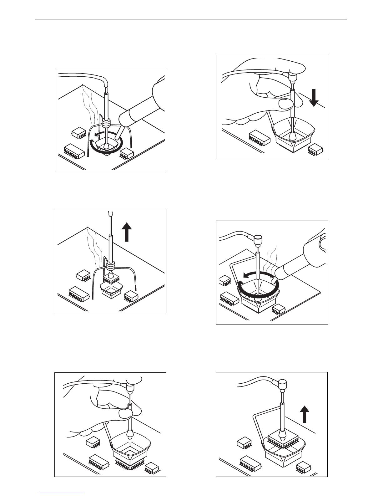
-Hot air for desoldering any size of SMD
components.
The station uses the exclusive JBC system,
based on protectors-extractors and hot-air
flow, which makes desoldering clean and quick,
concentrating the heat on the IC, and protecting
the rest of the circuit at the same time.
A medium-sized SMD can be desoldered in
less than 20 seconds.
-Desoldering SMTs and cleaning of through-
hole components and pads by using the DR
5600 desoldering iron, which contains a self-
contained vacuum pump.
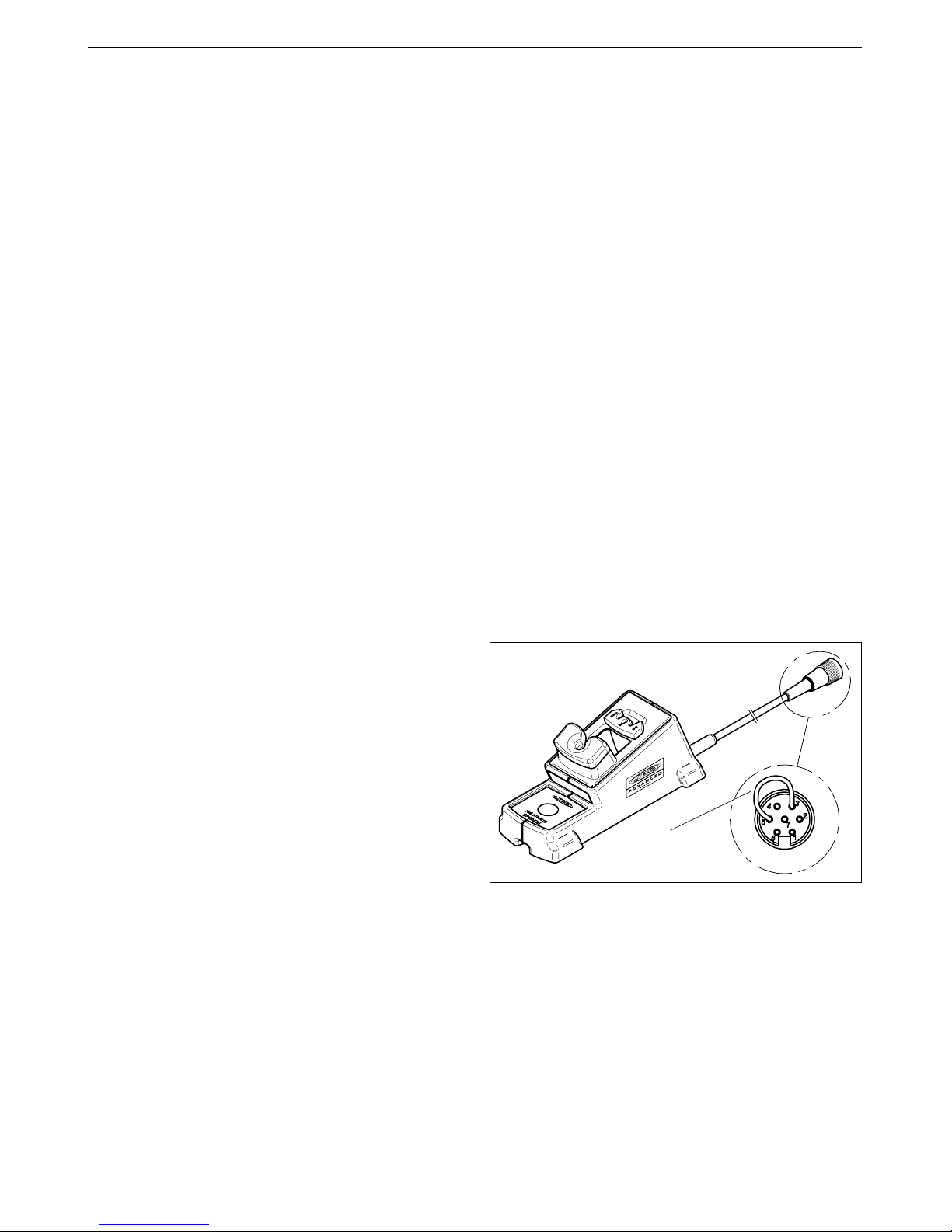
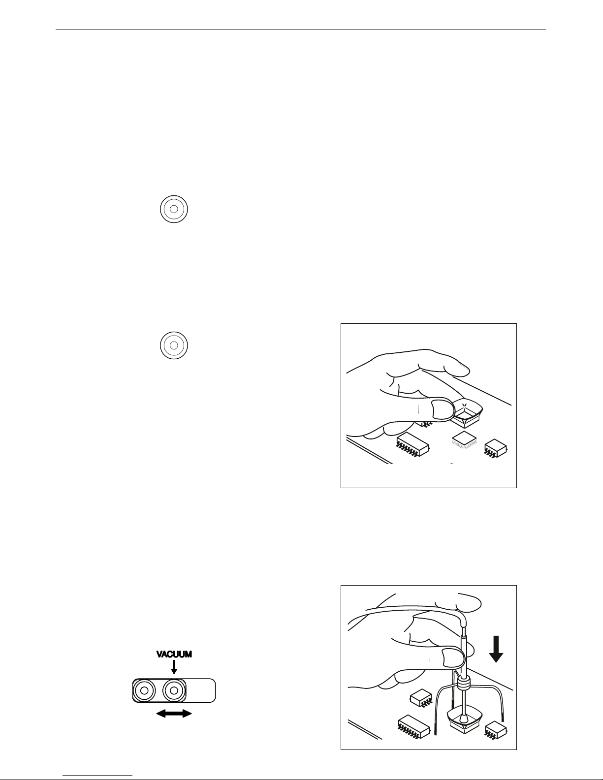
-Pick & Place MP 2260 pencil by suction to aid
components positioning.
-Soldering of all types of components, with the
swift response, power and temperature
recovery of the Advanced series.
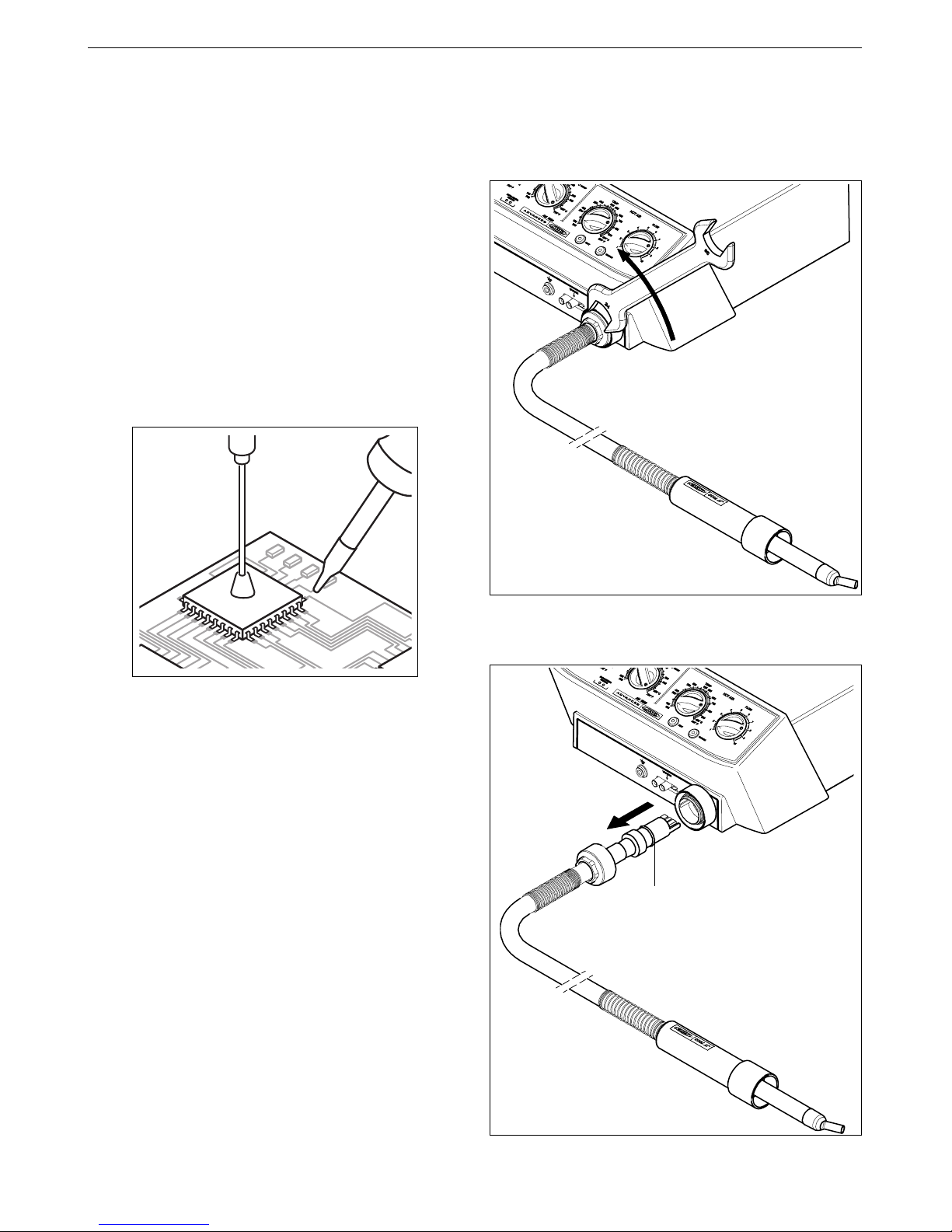
Any of the Advanced tools for soldering-Any of the Advanced tools for soldering-
Any of the Advanced tools for soldering-
desoldering can be connected to the two modules:desoldering can be connected to the two modules:
desoldering can be connected to the two modules:
the soldering handpieces, the DR 5600
desoldering iron, the AP 1300 solder feed iron and
the tweezers.
The standardization of connections allows you to
adapt your configuration in the best way to your
job's needs. Do notice that you can connect only
one desoldering iron.
In the station it is easy to verify which temperature
control module is controlling which tool. With all
tools in their stands take any one of them out of its
stand while watching the green LEDs of the station.
You will see that the LED of the module the tool is
connected to, will stop being intermittent thus
indicating the tool is ready for use.
The station’s components
- Control Unit with 900 W heater
-2245 handpiece Ref. 2245000
with the 2245-003 cartridge Ref. 2245003
-DR 5600 desoldering iron Ref. 5600000
with the 5600-003 tip Ref. 5600003
-MP 2260 Pick & Place Ref. 2260000
Accessories for the heater:
-JT 8700 heater stand Ref. 0828700
- Extractor stand Ref. 0932845
- Set of 5 protectors (Fig. 1, page 27)
- Set of 5 extractors (Fig. 2, page 27)
- 2 tripods for the protectors (Fig. 1, page 27)
- Set of 4 suction cups Ref. 0930110
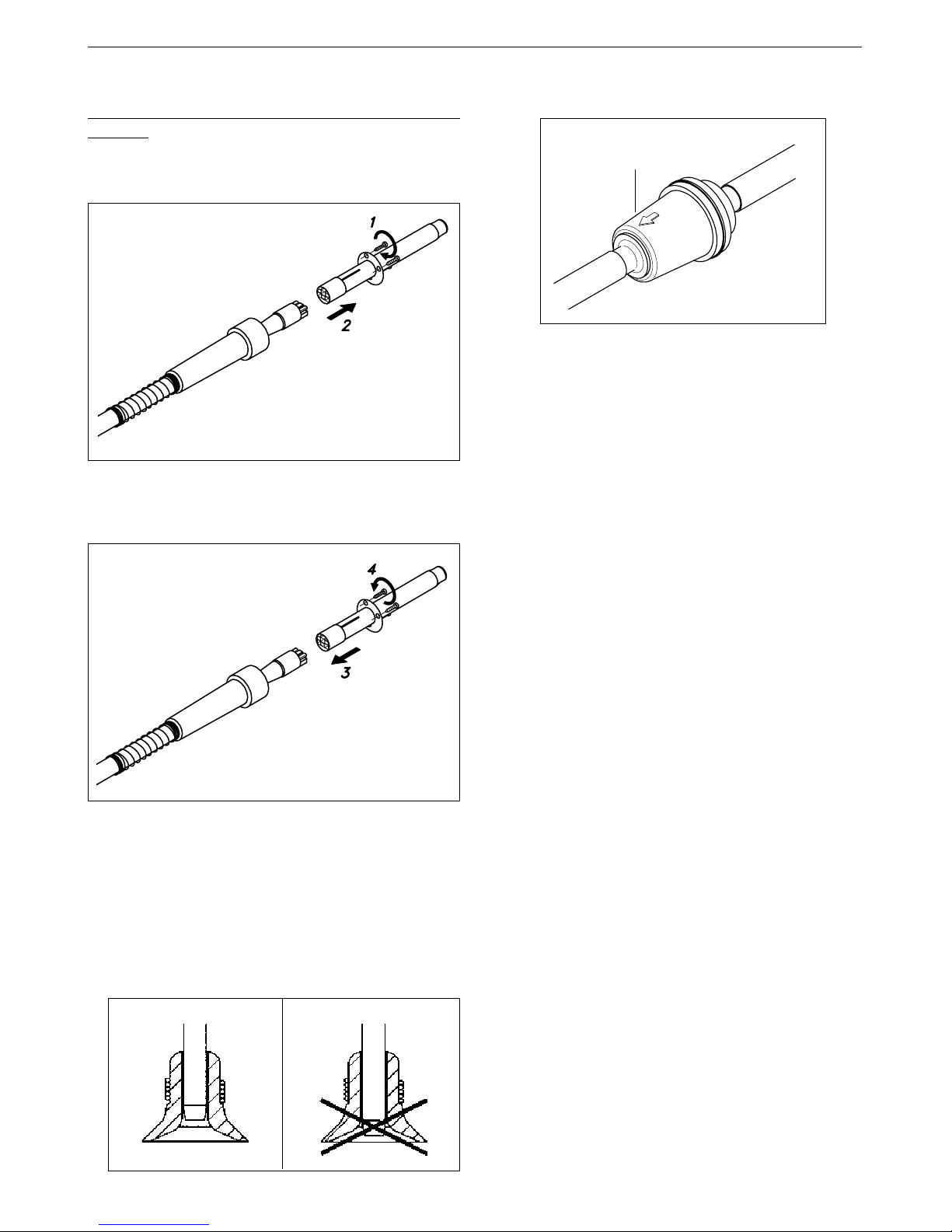
- 3 nozzles
In order to make the nozzles removal easier, the
stand has a special bushing.(Fig. 3, page 27).
- Suction tube with connectors Ref. 0932330
- Pedal with cable and connector Ref. 0964551
Accessories for the 2245 handpiece:
-AD 8245 soldering iron stand Ref. 0788245
Accessories for the desoldering iron:
-DR 8500
desoldering iron stand Ref. 0788500
- External desoldering air filter Ref. 0821830
- Spare filters Ref. 0781046
- Set of accessories Ref. 0780593
Accessories for the Pick & Place:
- Set of suction cups Pick & Place Ref. 0940163
- Set of straight needles Ref. 0901546
- Set of bent needles Ref. 0861660
- Instruction manual Ref. 0781056
The AM 6500 station has the following
complementary products:
-2210/2225 handpiece Ref. 2210000
-PA 1200 micro hot tweezers Ref. 1200000
-PA 4200 hot tweezers Ref. 4200000
-AP 1300 solder feed iron Ref. 1300000

3
Control Unit technical specifications
- Maximum power soldering iron 50W
- Maximum power desoldering iron 75W
- Power heating unit 900W
- Temperature selection of the soldering part:
200 to 700°F (±5%)
- Temperature selection hot air:
300 to 850°F (±5%)
- Air flow regulation: 6-45 l/min
- Self-contained vacuum pump for holding ICs
- Station's maximum power: 1150W
- ESD protected housing.
Typical surface resistance: 105-1011Ohms/
square
- Complies with CE standards on electrical
safety, electromagnetic compatibility and
antistatic protection.
- Equipotential connector and the tool tip are
connected to station mains ground supply for
ESD protection.
- Weight of complete unit: 44 lbs
RECOMMENDATIONS FOR USE
For soldering and desoldering
- Clean the contacts and the printed circuit
to be desoldered of dust or dirt.
- Preferably select a temperature below
662°F. Excess temperature may cause the
printed circuit tracks to break loose.
- The tip must be well tinned for good heat
conduction. If it has been inoperative for
any length of time, it should be retinned.
Safety measures
- Incorrect use of this tool may cause fire.
- Be cautious when using the tool in places
where inflamable products are stored.
- Heat can fire up inflamable products even
when they are not at sight.
- Do not use when the atmosphere is
explosive.
- Place the tool back on its stand in order to
let it cool down before you store it.

4
OPERATION
LED lights
Red LED -ON- when lit, it indicates that the station
is plugged in the mains.
Green LED -READY- when lit, it indicates that the
system is ready and correctly set for working.
The green led light is on after a few seconds, is the
time needed to carry on the self-checking system.
The green light is pulsing when the tool is in sleep
mode.
If the green led is not lit, the reason why, will be one
of the following:
1. The tool is not plugged in.
2. The maximum available power has been
exceeded for too long - e.g. in a very thick
soldering or desoldering at the high repetition
rates.
3. The heating element has a short circuit or an
open circuit.
4. When an AC 2600 console is connected to
the station.
5. Any other trouble preventing the system from
working properly.
If any of the above mentioned causes is corrected,
the station will start working automatically, except
if there is an excess in an energy supply. In this
case, the station has to be switched off and
restarted.
When pressing the button of the desoldering iron
handle, one of the two leds in the area marked
SUCTION will light up:
Green light -SUCTION- indicates the correct
functioning of the desoldering iron.
Red light -SUCTION- indicates a blockade
within the vacuum circuit.
This can be caused by the following:
- The tip of the desoldering iron is blocked.
- The solder tin deposit is full.
- The filter of the desoldering iron is dirty.
- The station’s external desoldering air filter is
dirty.
Only for users of AC 2600 console ref. 2600000.
If you lock the working temperature thanks to the
console, the green LED -READY- will remain on
while the dial is set at the locked temperature.
If the dial is not set at the locked temperature,
the green LED -READY- will be blinking. The
farther the dial will be set from the locked
temperature the slower the blinking pace will
be.
SLEEP FUNCTION
Tool in sleep mode
One of the Series Advanced features is that
when the tool is placed in the holder, the
temperature at the tip drops automatically to
the sleep temperature (sleep). This function
is only possible because of the quick
response time which does not make the user
realise the temperature rise to reach the
selected temperature. Thanks to the sleep
mode, oxidation levels at the tip are much lower
and therefore tip life extended to 3 to 5 times
under equal conditions of use.
To indicate that the tool is in sleep-mode, the
green led starts pulsing.
These parameters can be modified using the
AC 2600 console Ref. 2600000.
In order to take full advantage of the sleep
function and as a security measure, it is
necessary to place the tool in the stand
when it is not being used.
When connecting an old version solder stand, it
may happen that the sleep function does not work.
To resolve this problem, you should make a bridge
between pins number 3 and 5 from the aerial
connector of the cable of the stand, that plugs in
the station.
Aerial connector
Bridge between
pin number 3 & 5

5
OPERATION
Description of controls
-PEDAL:
Hot air is produced when it is held down.
Releasing it the heater is disconnected,
though the turbine continues to operate
until the air temperature falls below 212°F.
-BUTTONS:
Activates or desactivates the hot-air flow. After
a function-time of two minutes the hot-air flow
switches automatically off.
The red light indicates, that the heating element
is functioning. A malfunction is indicated by
the pulsing of the red led.
On/off switch for the self-contained suction
pump.
The yellow light of the switch indicates that
the self-contained vacuum pump is activated.
- CONTROLS:
TEMPERATURE
Allows fixing the temperature of the heater
between 300 and 850°F. The selected
temperatures are reference values which may
change depending on the distance between
the heating element and the nozzle.
Allows fixing the temperature of the soldering
and desoldering iron between 200 and 700°C.
AIR FLOW
This enables the air flow to be set on a scale from
1 (corresponding to the lowest setting of 6 l/min)
to 10 (corresponding to the highest of 45 l/min).
- VACUUM SELECTOR:
Two vacuum inlets avalaible, being active the
one that coincides with the arrow.
HEAT
VACUUM
DESOLDERING PROCEDURE WITH THE
HEATER
We would also recommend the use of the nozzles
of larger diameter, reserving the smallest one
(diam. 4 mm) for desoldering small components
such as resistors, condensers and the like, bearing
in mind that with this small nozzle the concentration
of heat is greater and care must be taken to avoid
burning the printed circuit; we recommend keeping
below a temperature of 662 °F and air flow of 6.
Depending on the size of the integrated circuit to
be desoldered, you will have to use:
A) Protector + tripod.
B) Extractor.
C)Tripod.
A)Protector + tripod:
- Select protector and tripod size in function of
the IC to be desoldered and place it over the
component.
- Use the VACUUM button to start the pump
and then fit the tripod. Press the sucker down
until it sticks onto the component.

6
- Use the pedal or the HEAT button to start the
self-contained hot-air pump, directing it with a
circular movement at the component terminals
and taking care to distribute the heat evenly.
- When the soldering flux turns liquid the
extractor will automatically lift the component.
B)Extractor:
- Select extractor size in function of the IC to be
desoldered. Use the VACUUM button to start
the pump.
- Fit the extractor and press the sucker down
until it sticks onto the component.
- Use the pedal or the HEAT button to start the
self-contained hot-air pump, directing it with a
circular movement at the component terminals
and taking care to distribute the heat evenly.
- When the soldering flux turns liquid the
extractor will automatically lift the component.

7
There are different models of protectors and
extractors as accessories.
The measurements of all the extractors and
protectors are given on page 27 of instructions
manual.
C)Tripod:
For small components for which an extractor
cannot be used, we recommend use of tripod 20
Ref. 0932050, as shown in the figure.
Use the tripod 40 Ref. 0932250 for larger integrated
circuits.
SOLDERING PROCEDURE
1 After desoldering the component, any solder
left on the printed circuit should be removed
with our DR 5600 desoldering iron ref. 5600000.
2 Place the component or printed circuit with
the MP 2260 Pick & Place ref. 2260000.
3 When the component is correctly placed,
solder its pins.In the case of integrated circuits
of the Flat Pack type, first solder one pin of
every IC angle to fix it in place in the circuits.
4 Apply FL 9582 flux ref. 0046565 in pads and
leads.
5 Solder the remaining pins. For this we
recommend to use our soldering irons of the
Advanced series, which are available in two
different models:

8
2210/2225 handpiece ref. 2210000 for great
precision tasks, like SMD solders, etc.
2245 handpiece ref. 2245000 for general
soldering tasks in professional electronics.
These soldering irons have a wide range of
cartridges with different models of tips. The
2245-009 cartridge and 2245-010 are
specially designed for soldering SMD circuits
of the QFP and PLCC types.
Solder wire with a diameter of between 0.5 and
0.7 mm should be used.
6 Depending on the nature of the component to
be soldered, use soldering paste together
with our TE 5000 hot air station, which gives
very accurate air-flow regulation, between 4
and 11 l/min.
Follow this process inverted to re-connect the
heater.
Move back the cover. Pull the connector from the
socket to disconnect the heater from the station.
MAINTENANCE
Exchanging the heater.
Turn off the station.
Use a wrench to unscrew the cover.
O-ring ø17 x ø1,8

9
OPERATING INCIDENTS
The suction cup does not adhere to the
component.
Deficient aspiration, Vacuum.
1 Verify if the suction cup is well placed and in
perfect condition.
Possible errors
In the case of malfunction, the control unit
interrupts the connection.
Following a list of the most common
malfunctions:
--
--
- Power failure.
Check for blown fuses.
- The temperature will not rise.
Possible causes:
· Heating element open.
· In case of a long low-power period.
- No reading from the thermocouple.
Possible cause: open thermocouple.
- Insufficient air flow which causes an excesive
rise of the heating temperature.
Before recuperating this type of error you must
wait until the temperature goes down.
Possible causes: leaking or blocked air
conducts or faulty self-contained air pump.
- Faulty reading of the rotationsmeter of the self-
contained air pump.
Possible causes: air pump damaged or faulty
function of the optical sensor circuit.
To recuperate any of these errors actuate the
general switch at the back of the station, the
pedal should not be pushed at this moment.
Filter
Ref. 0861800
2 Check the incoming air filter in the interior of
the station and replace it if dirty or obstructed.
Exchanging the resistor from the heater.
This step has to be performed when the heaterThis step has to be performed when the heater
This step has to be performed when the heater
is coldis cold
is coldis cold
is cold..
..
.
1. Untighten the screws.
3. Connect the new resistor, pushing it’s extreme.
4. Fix the screws tightly to avoid air-loss which
could reduce the resistor’s lifetime.
2. Separate the resistor from the heater’s cable.

10
DR 5600 DESOLDERING IRON
The AM 6500 station includes the following:
-DR 5600 desoldering iron ref. 5600000 with
the 5600-003 tip ref.5600003.
Power desoldering iron: 75W.
-DR 8500 desoldering iron stand ref. 0788500.
- External desoldering air filter ref. 0821830.
- Set of accessories ref. 0780593 with tips for
the desoldering iron: 5600-013, 5600-004 and
5600-005.
The desoldering iron is connected to the station
following the below procedure:
The cable connection of the desoldering iron is
connected to the plug in the DR 8500 desoldering
iron stand and the vacuum hose is connected to
the external desoldering air filter, which is
connected to the vacuum connection of the
station. The cable connection of the desoldering
iron stand can be connected to any of the two
connectors at the back of the station. Very
important, it is essential to connect the mentioned
filter to prevent from damaging the vacuum pump.
DR 8500
Desoldering iron stand
Ref.0788500
DR 5600
Desoldering iron
Ref.5600000
Heating element
Ref.5600010
Vacuum inlet
Connector
Spare filters
Ref.0781046
External desoldering air filter
Ref.0821830

11
DR 5600 Ref.5600000
Desoldering tip
Heating element
Pushbutton vacuum pump Vacuum hose
Desoldering iron cable
Solder tin deposit Metal
Glass
Desoldering process
Use the tip model with a larger diameter than
the pad to be desoldered, so as to achieve
maximum aspiration and thermal efficiency.
1Apply the desoldering iron tip so that the
component terminal penetrates within its
orifice.
2When the solder liquefies, start gently to
rotate the desoldering tip so that the
component’s terminal can be eased away
from the sides.
3Press then, not before, the vacuum pump
push-button just long enough to aspirate
the solder.
After pressing the desoldering key there is a
slight delay until the self-contained vacuum
pump stops, this is to make sure that the
vacuum circuit is completely empty.
If any solder remains are left on any terminal after
attempting to desolder it, resolder it with fresh
solder and repeat the desoldering operation.
123
Tip care
- The largest rod that fits in the tip hole should
periodically be passed through in order to
clean the intake tube.
- To clean the tips, use the sponge included
with the stand and check it is slightly
moisted.
Only deionised water (car battery water)Only deionised water (car battery water)
Only deionised water (car battery water)
should be used in order to wet the spongeshould be used in order to wet the sponge
should be used in order to wet the sponge.
If normal water was to be used, it is very
likely that the tip will become dirty due to the
salts dissolved within the water.
- Do not file the tips or use abrasive tools
which may damage the tip’s protective
surface coating and avoid knocking them
about.
- If the tip has been a long time without
being tinned, use a metal brush to remove
any dirt and oxid.
IMPORTANT::
::
: DO NOT press the pushbutton
vacuum pump while tinning the desoldering tip,
as the fumes given off by the flux would quickly
soil the ducts and filter of the air circuit.

12
Ref. 5600-001 5600-002 5600-003 5600-004 5600-005 5600-006 5600-007
5600
A ø (mm)
B ø (mm)
max. pin ø
(mm)
001 / 011
1.4
0.6
0.4
002 / 012
1.8
0.8
0.6
003 / 013
2.7
1
0.8
004
3.2
1.3
1.1
005
3.4
1.6
1.4
006
4.2
2
1.7
007
4.8
2.5
2.3
Aø
Bø
5600-012 5600-0135600-011
DESOLDERING TIPS
These tips are
specially designed to
clean the pads.
Change of desoldering tip
This operation should be done while the tip is
hot, at a minimum temperature of 482°F, so that
any tin left inside is in molten state.
- Unscrew the tip to be replaced, with the aid
of the spanner supplied.
- Fit the new tip, and tighten up with the
spanner to achieve a good air tightness.
To empty the solder tin deposit and change
the filter
For this, the lid needs to be unscrewed and first
the tin deposit and then its spiral must be
removed to clean the inner part of the deposit
with a brush.
- The condition of the filter must be checked
and replaced if dirty or damaged.
- The deposit needs to be inserted with
spiral filter put into place. Then the whole
must be closed by screwing the lid shut.
Lid
Brush
Ref. 0786640
Filter Ref.0780840
Deposit
Spiral
Ref. 0780550

13
Solder tin deposits
It can be chosen between two different deposit
types:
- Metal Ref. 0812630.
- Glass Ref. 0812620.
- Place the new heating element. Check that
the right extremity of the upper part of the
heating element is inserted in the slot
located inside the body of the desoldering
iron (see drawing hereunder).
- Screw out the body of the desoldering
iron. Open up the body and remove the
heating element.
- Screw in the body of the desoldering
iron. Put the spiral and the filter back
into the deposit. Place the deposit inside
the body of the desoldering iron and
screw in the shut lid.
Lid
Brush
Ref. 0786640
Filter Ref. 0780840
Deposit
Spiral
Heating element
Ref. 5600010
Change of the heating element of the
desoldering iron (Ref. 5600010)
- To realize this operation, the lid needs to
be unscrewed and first the tin deposit
and then its spiral and filter must be
removed to clean the inner part of the
deposit with a brush.

14
Cleaning the vacuum pump valve
Open the control unit as follow:
- Disconnect the control unit.
- Turn it upside down, remove the fixing
screws.
- Return the station to its normal position and
lift up the lid.
- Undo the four screws fastening the pump
cover.
- Clean the valve with a cloth dampened in
alcohol. If it is too soiled, replace it with
new one. Ref. 0982970.
Detecting air leaks in the circuit
To detect air leaks in the circuit:
- Obstruct the tip inlet
orifice by pressing down
on a silicone disc, or bend
the tube connecting the
desoldering iron to the
filter.
- Press the pushbutton vacuum pump.
If the red led lights up, there is no loss of
suction. Otherwise air gets into the system at
some point. This can occur at the desoldering
tip, or may be caused by the lid of the deposit,
lids of filters or because the air pump does
not function correctly due to dirty valves
which occurs when the air filter has not been
used correctly.
Changing the pump inlet filter
Verify the filter at the entrance of the pump, and
change it if dirty or obstructed, therefor:
Open the filter pulling the flap.
Take out the 2 cotton filters, throw away those
which are soiled and replace them with new
ones. Always use 2 filters.
Close the filter and check the airtightness.

15
MP 2260 PICK & PLACE PEN
The MP 2260 pick & place pen ref. 2260000 for
the placing of SMD is also delivered with the
AM 6500.
The pen is connected to the plug VACUUM of the
station. Please find the connection plan on page 1.
A set of straight and bent needles as well as a
set of different sized suction cups is delivered
with the station:
- Set of suction cups Ref. 0940163
- Set of straight needles Ref. 0901546
- Set of bent needles Ref. 0861660
The suction cups can be adjusted to the
needles in order to make the placement of SMD
of different sizes on boards easier.
These accessories allows the adjustment to
weight and size of any type of component.
Component pick-up (Fig. A)
Place the needle tip on the component and block
the control orifice with the first finger of the other
hand so that the component may be held to the
needle by suction.
Component placing (Fig. B)
Place the component in position on the printed
circuit. Remove your finger from the orifice
allowing air to enter whereby the component will
be released in the desired position.
Faults and remedies
We list below the most frequent faults and the
possible remedies which you yourself may be
able to apply. In any case, the JBC technical
assistance service will attend to you if required.
Insufficient suction
The tubes have to be checked for possible air
escapes and the correct connection of the tubes
to their terminals must be observed. Check the
incoming air filter in the interior of the station
and replace it if dirty or obstructed.
If in spite of this the suction is insufficient, the
self-contained vacuum pump should be
checked.
Filter
Ref. 0861800
When you assemble the suction cup with the
needle, you should avoid the needle to stick out
of the lower part.
Fig. A Fig. B
CUPS
Ref.: 0940163
STRAIGHT
NEEDLES
Ref.: 0901546
ØA
mm COLOR
2 x 4,3 BLACK
YELLOW2 x 7
PINK2 x 10
Ø B
mm
2 x 0,7
2 x 0,9
2 x 1,2
BENT
NEEDLES
Ref.: 0861660
COLOR
GREEN
YELLOW
PINK
Ø B
mm
2 x 0,8
2 x 0,9
2 x 1,2

16
AD 8210
soldering iron stand
Ref.0788210
2210/2225 handpiece Ref. 2210000
2245 handpiece Ref. 2245000
2245 cartridges
2210 cartridges
Connector
ADVANCED HANDPIECES RANGE
All the Advanced soldering handpieces range
can be connected to the AM 6500 station.
The AM 6500 station includes the following
products:
-2245 handpiece ref. 2245000 with the 2245-
003 cartridge Ref. 2245003. Power: 50W. For
general soldering work.
-AD 8245 soldering iron stand ref. 0788245.
- Set of accessories ref. 0780593 with 2245-007
cartridge Ref. 2245007. It can be chosen from
a wide range of different 2245 cartridges to
adapt perfectly to the needs of the job (pag.
24).
The following soldering handpiece can be
connected to the AM 6500 station:
-2210/2225 handpiece ref. 2210000. Power:
20W. For high precision work, SMD etc.
Available 2210 cartridges: see page 26.
The 2210/2225 handpiece has to be connected
to the AD 8210 stand which has been especially
designed for this handpiece.
One version of soldering iron handpiece
covered with a heat insulator is available:
-2245 Confort handpiece ref. 2245110.
These articles are not delivered with the station.
The 2210 and 2245 handpieces and cartridges
comply with the MIL-SPEC-2000 referring to
the potential difference between the soldering
tip and ground connection, must be less than 2
mV.
For a soldering handpiece to work properly,
the following components are required: a control
unit, a handpiece and the corresponding stand
and cartridge.
The soldering iron is connected to the station in
the following way:
The cable connection of the soldering iron is
connected to the plug in the soldering iron stand
and the cable connection of the soldering iron
stand can be connected to any of the two
connectors at the back of the station. Please
find the connection plan on figure.
AD 8245
soldering iron stand
Ref.0788245

17
Alignment
XX
XXXXX
Important.
- It is essential to insert the cartridge till the
end for a good connection. Take the mark
as reference.
2- Place the handpiece on top of the new
cartridge, press it slightly down and remove
the handpiece.
Changing the handpiece's cartridge
With the Advanced system, the cartridge can
be changed quickly, without turning off the
station, so you have two soldering irons in one.
Here is what to do to change the cartridge::
::
:
1- Place the handpiece and remove the
cartridge.
3- Press the cartridge into the opening A, B or C:
A. For straight 2210 cartridges.
B. For curved 2210 cartridges.
C. For 2245 cartridges.
Advanced series cartridge
The cartridge is made of the heating element
which has the heating system, a temperature
sensor and a long life tip.
The long-life tip is basically made of:
1Copper
2Iron
3Chromium
4Tin plate
Tip care recommendations
Except for the copper core, the rest of metals
are placed galvanically on relatively thin layers,
therefore it is necessary to avoid anything
which could cause their destruction.
To clean the tips, use the sponge included with
the stand and check that it is slightly moisted.
Only deionised water (car battery water) shouldOnly deionised water (car battery water) should
Only deionised water (car battery water) should
be used in order to wet the spongebe used in order to wet the sponge
be used in order to wet the sponge. If normal
water was to be used, it is very likely that the tip
will become dirty due to the salts dissolved within
the water.
To re-tin the soldering tips, we recommend
using the TT 9400 tip tinner/cleaner ref. 9400000.

18
JBC reserves the right to make technical changes without prior
notification.
Fume extractor accessories
Specially designed for the Advanced Series
2210/2225 and 2245 handpieces. Easily clips
onto the handpiece and can be quickly removed
for easy maintenance.
For 2245 handpiece:
Standard Ref.0495000
Confort Ref.0781324
+20mm longer Ref.0455002
For 2210/2225
handpiece
Ref.0265000
AC 2600 console
The AC 2600 console is designed for modifying
the original regulation program parameters of the
following Advanced control units:
-AD 2200, AD 2700 (**) and AD 3300 (**)
soldering stations.
-DI 3000 (**) and DI 2850 (**) digital soldering
stations.
-AD 4300 and DD 5700 (**) dual soldering
stations.
-AR 5800 (*) and DS 5300 (*) desoldering
stations.
-AM 6500 (*) rework station.
-DM 6700 4 tool station (**).
-AL 2500 solder feed system (**).
(*) These stations need a console whose
program version is 4.0 or higher.
(**) These stations need a console whose
program version is 5.01 or higher.
Changes avalaible to perform:
- Fixing the the working temperature.
- Selection of temperature units in Celsius grades
-°C- or Fahrenheit -°F-.
- Modification of sleep temperatures and standby
times.
- Adjustment of temperature.
- Set the parameters back to the original
parameters.
- Read-out data:
Working hours.
Sleep cycles and sleep hours.
Cartridge and iron changes.
Program version.
AC 2600
Ref. 2600000

19
AD 2200
Soldering stations for specialized use with SMD
components assemblies.
JT 7000
Hot-air flow repair station for desoldering all types
of SMD’s particulary QFPs and PLCCs of any size.
TE 5000
Hot-air flow repair station designed for soldering
and desoldering small and medium-sized SMDs.
AR 5800
Desoldering station which enable the rapid
desoldering of all kinds of insertion components.
Table of contents
Other jbc Rework Station manuals