10
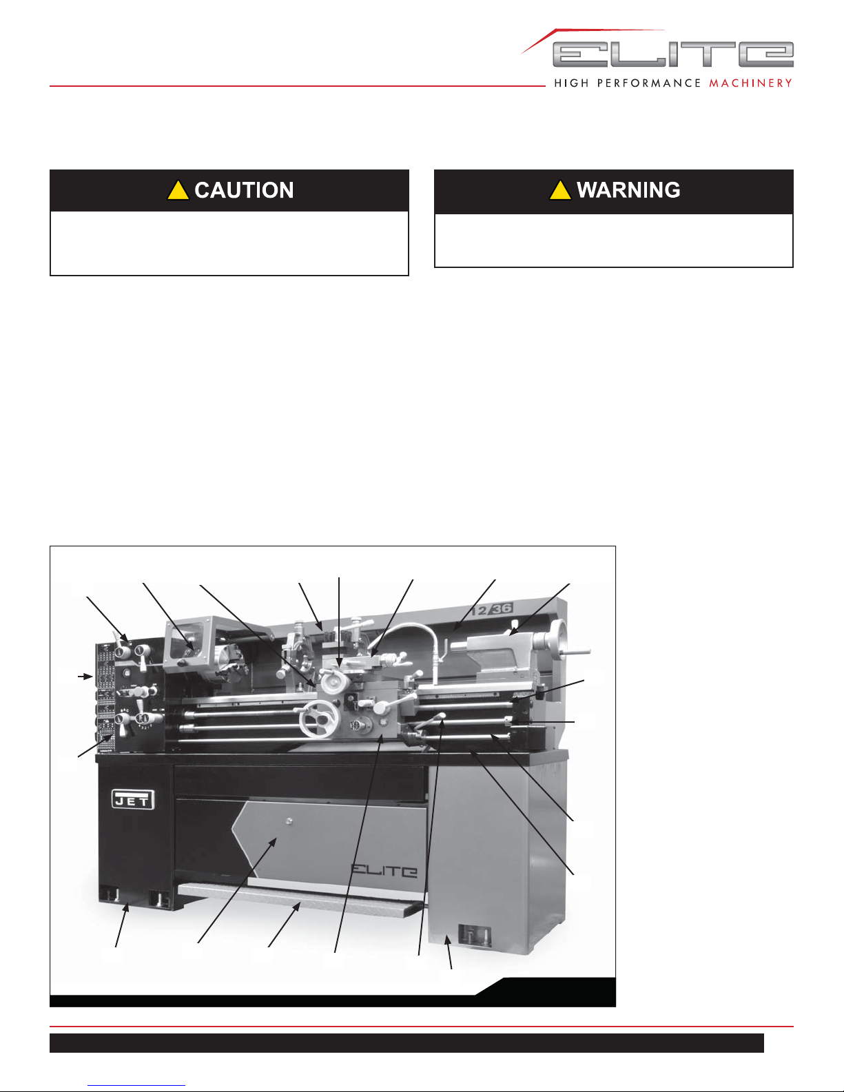
1236 Lathe
5.5 STANDARD ACCESSORIES
• Electrical equipment & Motor 2 HP
• Set of change gears - 1 set
• Center sleeve M.T. No. 5x3 - 1 pc.
• Two centers M.T. No.3 - 1 set
• Threading dial indicator - 1 set
• Toolbox; set of spanners & Keys - 1 set
• 4-ways turret toolpost - 1 pc.
• Toolpost wrench - 1 set
• 6 inch (150mm) dia. backplates - 1 pc.
• 3 - jaw scroll chuck 6 inch (150mm)
• Face plate 10 inch (250mm)
• Steady rest
• Follow rest
• Coolant pump equipment
• Splash guard
5.6 OPTIONAL ACCESSORIES
• 4 - jaw independent chuck 8 inch (200mm)
• Taper turning attachment
• Quick change toolpost
• Micro carriage stop
6.0 INSTALLATION
1. Finish removing all crate material from around lathe.
2. Unbolt lathe from shipping pallet.
3. Choose a location for the lathe that is dry and has
sufficient illumination (consult osha or ansi standards
for recommended lighting levels in workshop
environments).
4. Allow enough room to service the lathe on all four
sides, and to load and off-load work pieces. In addition,
if bar work is to be performed, allow enough space
for stock to extend out the headstock end. If used in
production operations, leave enough space for stacking
unfinished and finished parts.
5. The foundation must be solid to support the weight of
the machine and prevent vibration, preferably a solid
concrete floor.
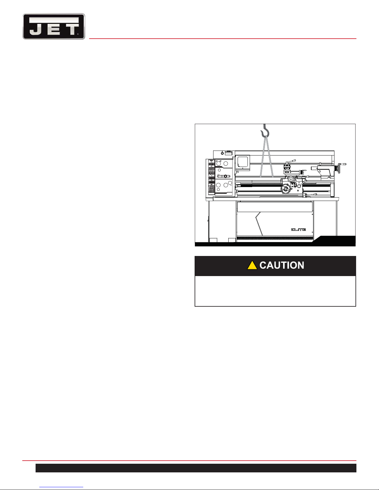
6. The lathe’s center of weight is near the headstock.
Before lifting, move the tailstock and the carriage
(release carriage lock, see section 11.0) To the right
end of the bed and lock them.
7. With properly rated lifting equipment, slowly raise lathe
off shipping pallet. (See Figure 4). Do not lift lathe by
the spindle.
HL
RPM
TOOGLE
STOPLATHE TO
CHANGESPEED
32 36 40 48 56
28
20 24
10 12 14
18
9
16
8
0.00280.0025 0.0023 0.0019 0.0016
0.00570.0051 0.0046 0.0038 0.0032
0.01150.0102 0.0092 0.0076 0.0065
0.01150.0102 0.0092 0.0076 0.0065
0.02300.0204 0.0184 0.0153 0.0131
0.04600.0409 0.0368 0.0307 0.0263
8
22
11
5.5
23
11.5
5.75
3 3 3
910 12 14
75 6
2.5 3 3.5
4.5
2.25
4
2
T.P.I
127
26
52
127
52
26
127
40
44
127
40
46
127
40
52
26
13
6.5
127
26
52
inch
127
52
26
mm
120
127 26
52 35
40 30
50
PC
MM
0.5 0.6 0.8
0.8 0.90.9
1.81.61.751.51.21.0
2.0 2.4 3.0 3.5 3.2 3.6
0.75 0.875
30
6050605030 30304040
1.8751.125 1.25
3.752.25
1.0
2.0
4.0 4.5 5.0 7.5 8.0
4.0
2.0 2.4 2.5 3.0
4.8 5.0 6.0
9.6 10 12
2.5
Leadscrew8 TPI
B
2
3
AC
1
45
Fig. 4
!
Confirm that all suspension equipment is properly
rated and in good condition for lifting lathe. Do not
allow anyone beneath or near load while lifting.
8. The lathe can be placed upon the cast iron leveling
pads under each foot hole, and adjusted using the
adjusting bolts with hex nuts. Or, it may be secured
to the floor using bolts placed head-down in the
concrete, and using shims where needed to level
the machine. Refer to Figure 1 for mounting hole
dimensions.
6.1 LEVELING THE LATHE
It is imperative that the lathe be on a level plane; that is,
where headstock and tailstock center points remain aligned
throughout the tailstock travel, with the bed ways absent of
twist and thus parallel to the operational center line.
A lathe which is not properly leveled will be inaccurate,
producing tapered cuts. Also, the center point of the
tailstock will vary as it is positioned along the bed, thus
requiring constant readjustment of the set of the tailstock.