Jet WRT-2000 User manual

WRT-2000 Electric Trolley
This Trolley is designed to run on standard “I” beams, wide-
flanged “H” beams, or curved track with a minimum radius of 1
meter (39.37 feet).
Specifications
Model Number.....................................................WRT-2000
Stock Number............................................................107004
Capacity ....................................................................... 1 ton
Motor...................................................... 1/8HP, 110V, 60Hz
Net Weight (lbs.)...............................................................31
Shipping Weight (lbs.)....................................................... 33
1. Beam must be properly installed and rated for anticipated
loads.
2. Do not install trolley on beams of unknown capacity.
3. Do not install trolley on damaged or deformed beams.
4. JET trolleys are designed to be used with hoists of the
same rated capacity. Never use a hoist with a capacity
greater than the capacity of the trolley.
5. Never subject trolley to a side pull or load. Load must be
centered directly under the hoist/trolley assembly.
6. Make sure load is stable and secure before moving.
7. Never lift load higher than is necessary to safely move it.
8. Do not allow anyone to work or stand beneath a raised load.
9. Always follow installation instructions.
10. Do not use this trolley if you are under the influence of drugs, alcohol or any medication.
11. Do not use in wet, damp or poorly lit location.
12. The electrical plug must be connected to a properly grounded receptacle. If in doubt as to whether a
receptacle is properly grounded, consult a qualified electrician.
WMH TOOL GROUP
2420 Vantage Drive
Elgin, Illinois 60124 Part No. M-107004
Ph.: 800-274-6848 Revision A1 8/06
www.wmhtoolgroup.com Copyright © WMH Tool Group

2
Figure 1
Installation and Adjustments
(refer to Figure 1)
Important: Use an assistant to help hold the trolley while you assemble it to the beam.
1. To adjust trolley width, remove split pins and slotted nuts (A) and slide out both shafts (G). Remove
washers (F) and collars (C) from shaft.
2. The trolley must be assembled to achieve two established measurements:
a. The trolley must be installed on a beam with a minimum clearance (wheels to flange) of 1/16”
to a maximum of 1/8” on each side of the beam. This clearance is shown as (H) in Figure 1.
Position the side plates (E) to achieve this measurement on your beam.
b. The angle irons (D) must be positioned so that the hole centerlines (J) match those of your
hoist. The angle irons should be evenly spaced from the side plates (E).
3. NOTE: Washers must be moved in sets of two, placing equal numbers on both sides to maintain the
centerline of the trolley.
4. Once the trolley width is spaced properly, install remaining washers on the bolt (same number on
both sides) on the outside of the side plates. Install slotted nuts and split pins. Do not over tighten
nuts. Tighten nuts, and then back nuts off as needed to clear the hole for the split pin. Insert split pin
through the hole in the shaft and bend down the ends of the split pin.
5. Double-check wheel clearance (H) and make further adjustments if necessary.
Replacement Parts
To order parts or reach our service department, call 1-800-274-6848 between 7:30 a.m. and 6:00 p.m.
(CST), Monday through Friday. Having the Model Number and Serial Number of your product available
when you call will allow us to serve you quickly and accurately.

3
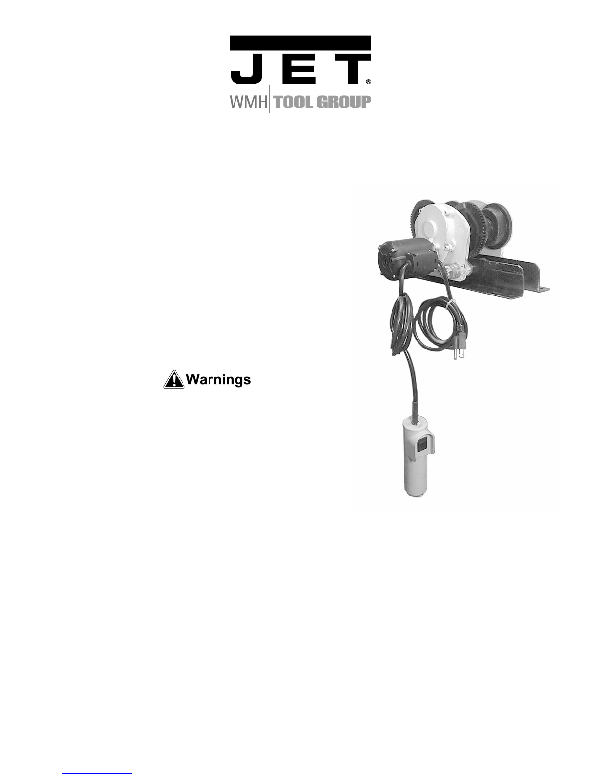
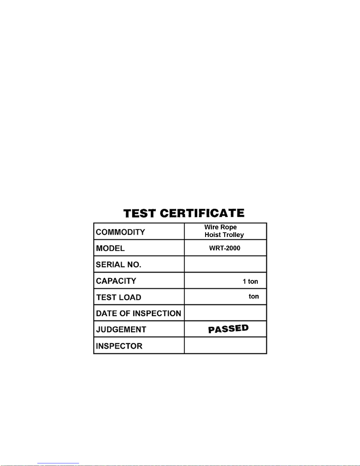
WRT-2000 Wire Rope Hoist Trolley
Index No. Part No. Description Size Qty
1...............WRT2000-1............. Split Pin.......................................................Ø4mm...............................4
2...............WRT2000-2............. Angle Iron (RH)............................................ .........................................1
3...............WRT2000-3............. Collar........................................................... .........................................4
4...............WRT2000-4............. Pinion.......................................................... .........................................1
5...............WRT2000-5............. Flat Key.......................................................Ø5x10mm.........................1
6...............WRT2000-6............. Angle Iron (LH)............................................ .........................................1
7...............WRT2000-7............. Pinion.......................................................... .........................................1
8...............WRT2000-8............. Bushing.......................................................7x10x9mm........................1
9...............WRT2000-9............. Motor Pin..................................................... .........................................1
10.............WRT2000-10........... Pin...............................................................Ø5x18mm.........................2
11.............WRT2000-11........... Socket Head Cap Screw..............................M5x10...............................4
12.............WRT2000-12........... Motor........................................................... .........................................1
13.............WRT2000-13........... Slotted Nut................................................... .........................................4
14.............WRT2000-14........... Shaft............................................................ .........................................2
15.............WRT2000-15........... Washer........................................................Ø18mm...........................44
16.............WRT2000-16........... Side Plate (RH)............................................ .........................................1
17.............WRT2000-17........... Seal Washer................................................ .........................................4
18.............WRT2000-18........... Snap Ring....................................................Ø20mm.............................4
19.............WRT2000-19........... Bearing........................................................60204-2RS .......................4
20.............WRT2000-20........... Wheel.......................................................... .........................................2
21.............WRT2000-21........... Seal............................................................. .........................................4
22.............WRT2000-22........... Snap Ring....................................................Ø47mm.............................8
23.............WRT2000-23........... Geared Wheel ............................................. .........................................2
24.............WRT2000-24........... Snap Ring....................................................Ø47 ..................................1
25.............WRT2000-25........... Grooved Ball Bearing...................................50204-2RS .......................1
26.............WRT2000-26........... Side Plate (LH)............................................ .........................................1
27.............WRT2000-27........... Gear............................................................ .........................................1
28.............WRT2000-28........... Snap Ring....................................................Ø17mm.............................1
29.............WRT2000-29........... Grooved Ball Bearing...................................6200-2RS .........................1
30.............WRT2000-30........... Gear Box..................................................... .........................................1

4
31.............WRT2000-31........... Flat Washer.................................................Ø6mm...............................4
32.............WRT2000-32........... Lock Washer................................................Ø6mm...............................4
33.............WRT2000-33........... Socket Head Cap Screw..............................M6x18...............................4
34.............WRT2000-34........... Cable........................................................... .........................................8
35.............WRT2000-35........... Terminal Sleeve........................................... .........................................2
36.............WRT2000-36........... Strain Relief.................................................Ø7mm...............................1
37.............WRT2000-37........... Strain Relief.................................................Ø8mm...............................1
38.............WRT2000-38........... Phillips Pan Head Machine Screw................M3x12...............................4
39.............WRT2000-39........... Connecting Box ........................................... .........................................1
40.............WRT2000-40........... Clamp Plate................................................. .........................................3
41.............TS-1550021............ Flat Washer.................................................M4..................................10
42.............WRT2000-42........... Self-Tap Screw............................................M4x16...............................6
43.............WRT2000-43........... Electrical Plug.............................................. .........................................1
44.............WRT2000-44........... External Tooth LockWasher........................Ø4mm...............................1
45.............TS-1532012............ Phillips Pan Head Machine Screw................M4x6.................................1
46.............WRT2000-46........... Rocker Switch.............................................. .........................................1
47.............WRT2000-47........... Handle Cover............................................... .........................................1
48.............WRT2000-48........... Capacitor..................................................... .........................................1
49.............WRT2000-49........... Handle Base................................................ .........................................1
50.............WRT2000-50........... Strain Relief................................................. .........................................1
51.............WRT2000-51........... Pan Head Self-Tap Screw............................M3.5x20............................3
52.............WRT2000-52........... Terminal ...................................................... .........................................3
53.............WRT2000-53........... Terminal Sleeve........................................... .........................................3
54.............WRT2000-54........... Cable........................................................... .........................................1
WMH Tool Group
2420 Vantage Drive
Elgin, Illinois 60124
Phone: 800-274-6848
www.wmhtoolgroup.com
Table of contents
Other Jet Power Tools manuals