Jofemar Coffeemar G-250 User manual

Coffeemar G-250
//
Coffee
MNP116M01GBV00 Date: 09/04/2013 Rev. 1 PAGE 1 OF 95
English
Coffeemar
G-250
TECHNICAL MANUAL

Coffeemar G-250
//
Coffee
MNP116M01GBV00 Date: 09/04/2013 Rev. 1 PAGE 2 OF 95
WARNING
Read the following instructions carefully before installing the unit:
◊ Th s dev ce can be used by ch ldren from 8 years old and people w th phys cal,
sensor al or mental reduced ab l t es or w th lack of exper ence and knowledge, f they
are superv sed or have rece ved the requ red tra n ng for a safe use of the mach ne
and they understand the nvolved r sks. Ch ldren should not play w th the mach ne.
Clean ng and ma ntenance must not be done by ch ldren w thout superv s on.
◊ Take the machine down from the pallet and place t on the floor.
◊ When discarding packaging material or an old machine, please consult about
recycl ng.
◊ Before connecting to electricity or water mains, make sure that the supply
character st cs co nc de w th those of the mach ne.
◊ The power cable plug should be nstalled so the mach ne can be eas ly
d sconnected from ma ns.
◊ If the power cable is damaged, t should be replaced by the manufacturer or after
sales serv ce or s m lar qual f ed personnel to prevent hazards.
◊ Place a rubber protection around the power cable n the slot of the l d of the cable
w nd ng recess.
◊ Do not burn or throw away the battery. Batter es should be d sposed of n
accordance w th local laws and regulat ons and can be recycled.
◊ Protect the machine aga nst hum d ty, dust, d rt, etc. You should part cularly avo d
any obstruct on of the vent lat on gr lles.
◊ Do not clean the machine w th concentrated products as they may attack the
pa nt and alter the colour.
◊ Frequent cleaning, can prevent breakdowns and extend the mach ne's l fe.
◊ It s compulsory wearing gloves to man pulate the ns de and charge the mach ne.
◊ The machine should be installed n a vert cal pos t on, both laterally and back to
front, w th a max mum ncl nat on of 5% (~2°).
◊ If you need to replace the power supply cable, please replace t w th the
appropr ate one for your country:
Argent na, Jofemar code 5500014.
Austral a, Jofemar code 5500006.
Spa n (STANDARD), Jofemar code 5500000.
UK, Jofemar code 5500011.
Sw tzerland, Jofemar code 5500004.
USA, Jofemar code 5500010.
Jofemar S.A.
Ctra. de Marc lla km. 2, 31350 Peralta. Navarra, Spain.
http: // www.jofemar.com Tel. +34 948 75 12 12 Fax +34 948 75 04 20

Coffeemar G-250
//
Coffee
MNP116M01GBV00 Date: 09/04/2013 Rev. 1 PAGE 3 OF 95
TABLE OF CONTENTS
1. Symbols .................................................................................................................... 4
2. Operat ng cond t ons .................................................................................................. 4
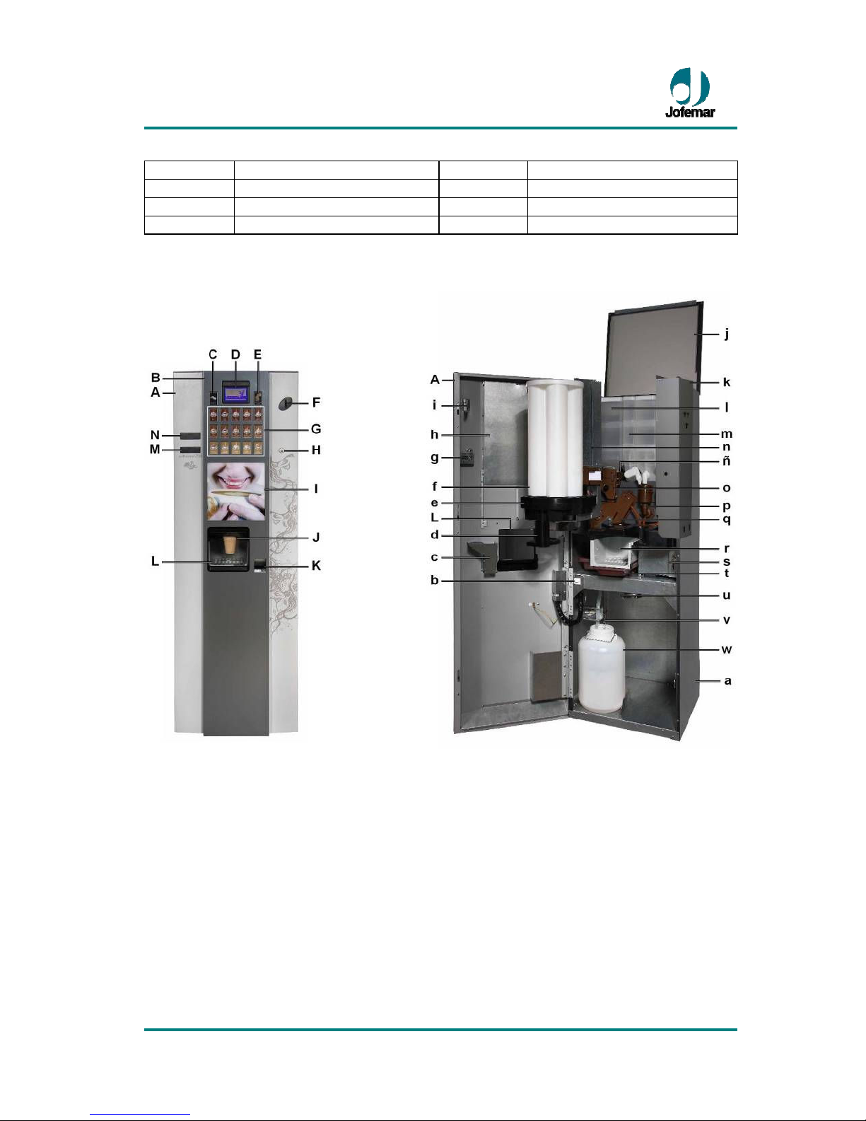
3. Descr pt on of components ........................................................................................ 4
3.1. Ma n techn cal features...................................................................................... 5
3.1.1. Door .......................................................................................................... 6
3.1.2 Cab net ...................................................................................................... 8
3.2. Volume and we ght .................................................................................... 27
4. Electr cal and electron c spec f cat ons ................................................................ 28
4.1. In t al electr cal nstallat on ........................................................................... 29
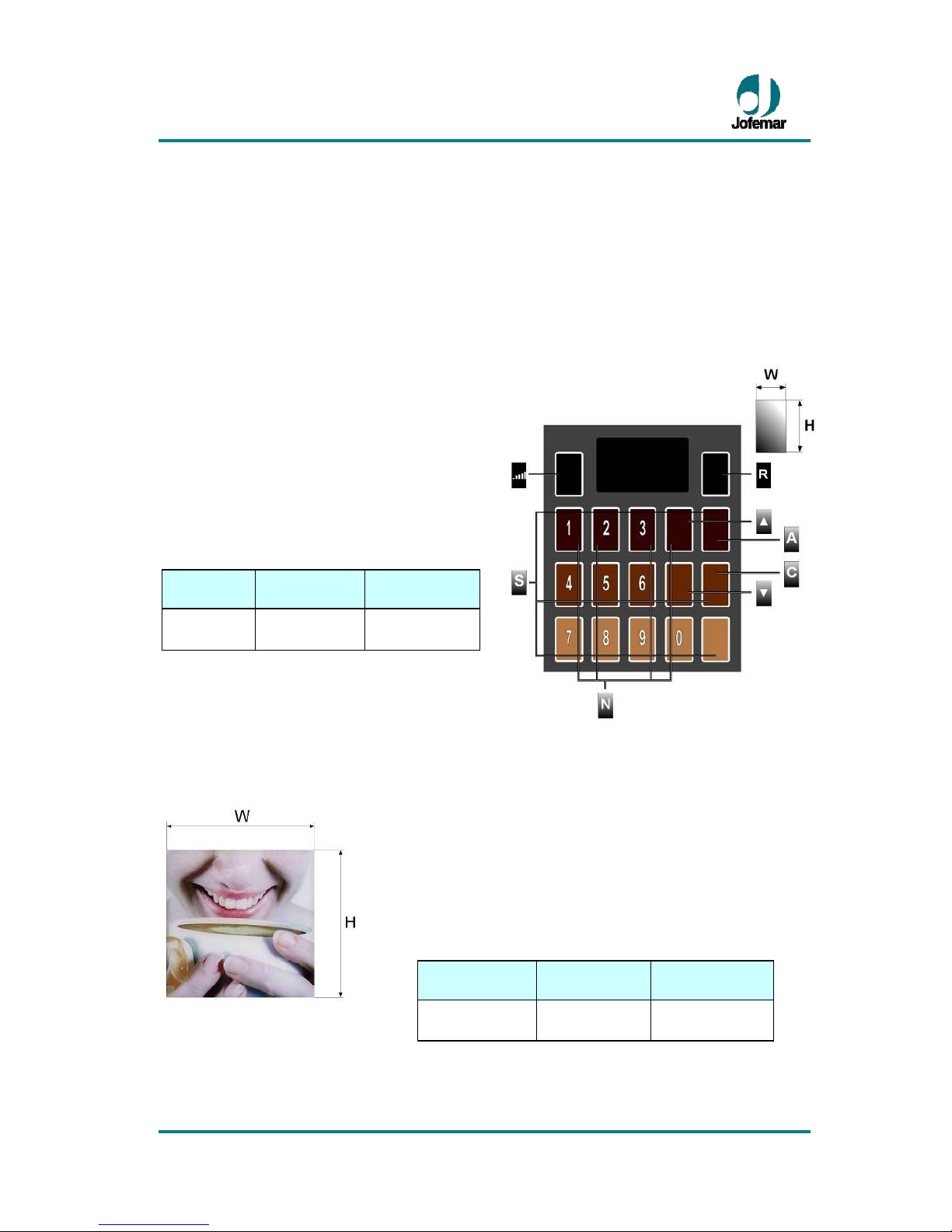
4.2. D splay card .................................................................................................... 29
4.3. Control card .................................................................................................... 31
4.4. Electron cs assembly ....................................................................................... 32
4.5. Val dator (selector) .......................................................................................... 33
4.6. Compact (MDB) .............................................................................................. 33
4.7. Recovery motor ............................................................................................... 34
4.8. Electr cal draw ng ............................................................................................ 35
4.9. Water c rcu t .................................................................................................... 36
5. Installat on and start-up. .......................................................................................... 37
5.1. Installat on ....................................................................................................... 37
5.2. Connect on to ma ns ................................................................................... 37
5.3. Connect on to water ma ns .............................................................................. 38
5.4. F ll ng the water c rcu t ..................................................................................... 39
5.5. Cup load ng ..................................................................................................... 40
5.6. St r-st ck load ng .............................................................................................. 41
5.7. Start-up ........................................................................................................... 43
5.8. Insert ng product cards .................................................................................... 43
5.9. Load ng soluble products ................................................................................. 43
5.10. Product select on ........................................................................................... 44
5.11. Updat ng the mach ne program ..................................................................... 45
5.12. Mach ne reset ................................................................................................ 46
5.13. Mach ne programm ng mode ......................................................................... 47
5.13.1. Standby menu w thout cred t (standby status) ....................................... 47
5.13.2. Standby menu w th cred t (work ng status) ............................................ 48
5.13.3. Programm ng menu (programm ng status) ........................................ 48
5.14. Programm ng addresses (Ma n Menu) ........................................................... 49
7. Annexes ................................................................................................................. 81
7.1. Per pherals (Opt ons ) ..................................................................................... 81
8. Clean ng and Ma ntenance ...................................................................................... 87
9. Recycl ng ................................................................................................................. 93
10. Env ronment
.......................................................................................... 93
11. Regulat ons ........................................................................................................... 93

Coffeemar G-250
//
Coffee
MNP116M01GBV00 Date: 09/04/2013 Rev. 1 PAGE 4 OF 95
1. Symbols
Th s symbol means there are more deta led explanat ons on th s subject elsewhere
n the manual.
Th s symbol means that the text n quest on refers to programm ng.
Th s symbol nd cates very mportant nformat on.
Th s symbol s a warn ng of h gh voltage hazard.
Th s symbol nd cates that a g ven mater al should not be d sposed of as
domest c waste.
Th s symbol nd cates that a g ven mater al s recyclable.
Th s symbol nd cates that Jofemar s comm tted to the env ronment.
2. Operating conditions
Th s dev ce s not ntended for outdoor use. . The mach ne leaves the factory adjusted to
work properly at an amb ent temperature between 5 °C and 32 °C (41 °F and 89.6 °F)
w th a max mum hum d ty of 60%.
If t s poss ble that the dev ce suffers freez ng dur ng
ts transport to the dest nat on, t s requ red to purge the hydr c c rcu t before the
transport takes place.
3. Description of components
Position
Description
Position
Description
A
Door
f
Cup conta ner
B
Door frame
g
Door closure
C
Sugar level pushbutton
h
Pushbutton protector
D
D splay
i
Co n entry gu de
E
Co n return pushbutton
j
Top cab net l d
F
Co n slot
k
Compact support
G
Product select on buttons
l
Coffee bean conta ner
H
Lock
m
Soluble conta ners
I
Advert s ng panel
n
St r-st ck support assembly
J
Product del very
ñ
Gr nder assembly
K
Co n return recess
o
Measur ng assembly
L
Protect ve door
p
Beater assembly
M
Key/card reader (opt.)
q
Brew ng assembly
N
Banknote reader (opt onal)
r
Gr lle
a
Cab net
s
Vault support

Coffeemar G-250
//
Coffee
MNP116M01GBV00 Date: 09/04/2013 Rev. 1 PAGE 5 OF 95
b
Open door safety sw tch
t
Waste l qu d tray
c
Co n ex t gu de
u
Coffee grounds outlet
d
Cup support arm
v
Floater
e
Cup d spenser
w
Waste l qu d tank
3.1. Main technical features
► Automat c d spenser of freshly-made espresso coffee and soluble beverages.
► Serv ngs are d spensed to a plast c cup or the user’s own mug.
► Easy, flex ble conf gurat on and programm ng, w th up to 15 pushbuttons to adapt the
mach ne to the requ rements of each cl ent.
► Each pushbutton del vers a g ven product and ts var ables (espresso coffee,
decaffe nated coffee, chocolate, m lk, tea) and sugar pre-select on.
► Automat c brew ng pressure.

Coffeemar G-250
//
Coffee
MNP116M01GBV00 Date: 09/04/2013 Rev. 1 PAGE 6 OF 95
► Large LCD d splay w th d rect status and programm ng messages.
► Telemetry-ready, nclud ng remote read ng of aud ts, sales, nc dents and changes n
programm ng opt ons.
► Sales account ng and control, as well as data output v a RS-232-C. The mach ne can
also be programmed v a a Jofemar electron c term nal.
► Cont nuous operat onal self-test ng
► LED-backl t advert s ng panel and product select on buttons.
► Three-po nt secur ty lock.
► The metal parts are constructed n 1 mm (0.039”) th ck plate.
3.1.1. Door
The door assembly cons sts of two parts, the door and the door frame. Both parts are
protected w th rustproof ng treatment plus an external coat of rustproof ng pa nt.
The doorframe holds the d splay, the product select on buttons, the co n return button,
the advert s ng panel, co n return box and the product del very open ng. The door tself
has the co n nsert and lock and can opt onally be f tted w th a banknote reader and a
card reader . The programm ng pushbutton s on the back of the door.
Display
The d splay shows the drop-down menus and s
used n mach ne programm ng operat ons,
d splay ng aud t data and techn cal nc dents, as
well as d splay ng ava lable cred t and product
sale pr ces.
► It can also reproduce an mat ons.
Height
(H1/H2)
Width
(W1/W2)
INTERIOR 45 mm
(1.772”) 84 mm
(3.307”)
EXTERIOR 53 mm
(2.087”) 92 mm
(3.622”)
Fig. 01

Coffeemar G-250
//
Coffee
MNP116M01GBV00 Date: 09/04/2013 Rev. 1 PAGE 7 OF 95
Selection pushbutton panel
At the top-left there s a sugar +/- pre-select on pushbutton (
▌
▌
▌
▌
▌
). At the same he ght,
on the left, there s a co n return button (R) used to recover co ns that have been nserted
( f the user w shes to recover the amount that has prev ously been nserted).
The product select on pushbutton panel has eas ly-v s ble pushbuttons (S) for d rect
access to 15 d fferent products.
The four pushbuttons dent f ed as ▲, ▼,
A
and C are used for product select on but
also for programm ng and mach ne
conf gurat on purposes. The numbered
pushbuttons (N) 1, 2, 3, 4, 5, 6, 7, 8, 9 and
0 are used to enter pr ces, (see f g. 02).
Fig. 02
H
eight
(H) Width (W)
Thickness
(F)
50 mm
(1.969”) 30 mm
(1.181”) 0.8 mm
(0.049”)
Advertising panel
Fig. 03
The panel s used to custom se the mach ne’s aspect. It
can be used w th any mot f.
To replace the panel, go to the back of the door and do as
follows: 1st unscrew the product card protect ve plate;
2nd, remove the two s de plates; and 3rd, remove the top
bracket.
You can then remove the panel.
Height (H) Width (W)
Thickness
(F)
255 mm
10.039” 245 mm
9.646” 3 mm
0.118“

Coffeemar G-250
//
Coffee
MNP116M01GBV00 Date: 09/04/2013 Rev. 1 PAGE 8 OF 95
Lighting
The l ght ng system has two parts, one to l ght up the advert s ng panel and the other to
l ght up the product select on buttons.
The l ght ng system s and LED-based system that ncludes the follow ng two features:
Un form l ght ng and low power consumpt on. It employs a 12V power supply.
Fig. 04
Coin slot
Th s s a standard co n slot constructed from Zamak.
Lock
The mach nes come equ pped w th a secur ty lock cons st ng of a plate and three vandal-
proof anchor po nts.
Programming pushbutton
It s located at the back of the
door above the product card
protect ve plate, (see f g. 05),
and t s used to access all
programm ng opt ons: sale
pr ces, messages to be
shown on the d splay, resets,
etc.
Fig. 05
3.1.2 Cabinet
The cab net s constructed w th plast c-coated plate made of stress-proof mater al. The
top cab net l d s made of the same mater al as the cab net and prov des access for
restock ng product conta ners.
The m ddle area has the cup d spens ng assembly, the cup storage tube assembly, the
st r-st ck d spenser and the sugar conta ner.
The cab net conta ns the follow ng: the doser, the m ll, the brew ng assembly, the gra n
and soluble product conta ners, the beaters, the compact, the selector, the recovery
motor, the l qu d waste tank, coffee grounds outlet. The follow ng components are

Coffeemar G-250
//
Coffee
MNP116M01GBV00 Date: 09/04/2013 Rev. 1 PAGE 9 OF 95
located at the back of the cab net: the power assembly, the water nlet soleno d valve,
the a r-break, the soluble product d str butor, the pressure bo ler, the pressure pump and
the volume counter.
Cup dispenser assembly
The cup d spens ng assembly cons sts of a storage un t w th 5, tube-shaped columns
that have an nternal d ameter of 78 mm (3.071”). The columns are jo nt by flanges
runn ng down the r full length, compr s ng a compact assembly. The assembly has a
pressure f tted star-shaped p ece that f ts ns de the gap left by the f ve tubes and serves
to mount t on the shaft that supports the cup d spenser .
Fig. 06
The total capac ty of the cup storage assembly s 250 cups.
The cup d spenser has a control system that employs
photocells to detect whether cups are present or not. When
the photocell beam s un nterrupted, the 12 V geared motor
ns de the d spenser starts and turns the storage assembly to
the next pos t on, controlled by the storage assembly pos t on
m crosw tch. If there are cups n the column, the r own we ght
pushes them down unt l they reach the hole on the d spenser
cover, block ng the l ght beam from the photocell system. If
every column s empty, the cup storage assembly w ll rotate
through 8 consecut ve pos t ons, to make sure that there are
no cups n any column, n wh ch case t w ll leave the mach ne
out of serv ce.
The cup for each serv ng s del vered by the cup d spenser . It cons sts of a 12 V geared
motor that s multaneously turns 5 cogwheels. The movement of these cogwheels
releases the cup rest ng on them at the same t me that t restra ns the other cups n the
stack (see f g. 07).
Note: The type of cup to be used has to be taken nto account.
Furthermore, w th n each class, the d spens ng cogwheels can be adapted to cup
d ameter at 0.5 mm (0.020”) ntervals. There s a cogwheel d splacement system that
allows you to br ng them closer to or further away from the cup centre. Follow these
steps to choose the most appropr ate system to d spense cups:
1. After dec d ng on the cup to be used, measure the d ameter at the base of the support
r ng and determ ne wh ch category the cup belongs to, 65-67 mm (2.559”–2.638”) or 67-
69 mm (2.638”–2.717”). Please note that the d spenser cogwheels, the cup collector
supplement and the cup sl de w ll be d fferent n each case.

Coffeemar G-250
//
Coffee
MNP116M01GBV00 Date: 09/04/2013 Rev. 1 PAGE 10 OF 95
2. Once you have def ned the cup n terms of ts class f cat on, choose the most
appropr ate cogwheel pos t on. To do th s, the cup d spenser assembly has 5
ntermed ate pos t ons for the 2 mm (0.079”) d stance between the largest and smallest
d ameter at 0.5 mm (0.020”) ntervals. Cogwheel pos t on 1 corresponds to the smallest
d ameter, wh le pos t on 5 s for the largest d ameter. The other pos t ons are obta ned by
add ng 0.5 mm (0.020”) ntervals. Choose the pos t on mmed ately above the closest to
cup d ameter (see f g. 07)
CUP DISPENSER
A.
Cogwheel pos t on lock ng shaft
B.
Cup d spenser lower bush ng
C.
Manual cup d spens ng button
Fig. 07
To change the pos t on of the cup d spenser wheels do as follows:
Remove the cup storage assembly tubes and the star-shaped p ece.
1. L ft the cogwheel block ng shaft by hold ng the end of the shaft that st cks out of the
cup d spenser l d and pull ng t unt l the other end comes out of ts recess.
2. Gr p the lower cup d spenser bush ng and turn t n one or the other d rect on unt l the
nd cator arrow co nc des w th the des red pos t on.
3. Release the shaft that w ll return to ts recess thanks to the spr ng attached to t. To
ensure the shaft s properly anchored, press the shaft down to check that t has gone all
the way nto ts recess.
Note: Cups can be d spensed manually by press ng the button on the d spenser cover
(see f g. 07).

Coffeemar G-250
//
Coffee
MNP116M01GBV00 Date: 09/04/2013 Rev. 1 PAGE 11 OF 95
Stir-stick container
When a cup s d spensed, t falls nto a collector that gu des t to brew ng pos t on. Before
water s d spensed from the bo ler to the cup, the sugar and st r-st ck have to be f rst
added.
The st r-st cks are located n a sl de w th a capac ty of
approx mately 250 st r-st cks. They are d spensed by a
flap that pulls the st r-st ck lean ng aga nst the d spenser
at the bottom of the sl de. The flap s dr ven by a 12 V
geared motor. The st r-st ck sl des through a collector to
the cup.
The st r-st cks should be between 75 and 115 mm
(2.953”-4.528") long and between 1.25 and 1.75 mm
(0.049”–0.069”) w de.
The length of the st r-st ck s adjusted to the channel
w th the st r-st ck length adjuster.
A.
St r-st ck sl de
B.
D spenser front cover
C.
D spenser flap
D.
12 Vdc geared motor
E.
Funnel
Fig. 08
Product containers
The conta ners are made of food grade polypropylene that s translucent so you read ly
see how much product they conta n.
Each conta ner s espec ally des gned to hold coffee beans, decaffe nated coffee,
chocolate, m lk, tea/soup or sugar, and capac ty depends on product type. The
conta ners are modular p eces.
The sugar and st r-st ck d spensers are mounted an assembly located ns de the door, on
flanges. Th s system allows for the complete assembly to turn, to make t eas er to load
sugar. The assembly also features an anchor ng system to ensure the d spenser’s
pos t on w th respect to the cup s ma nta ned. The sugar conta ner s dent cal to the
soluble conta ners (short worm) but nstead of hav ng an elbow at the outlet, t s
equ pped w th a rotat ng door wh ch opens only when the ma n door that allows the

Coffeemar G-250
//
Coffee
MNP116M01GBV00 Date: 09/04/2013 Rev. 1 PAGE 12 OF 95
product to be d spensed nto the cup closes. To prevent the sugar from cak ng on the
conta ner outlet, there s a steam exhaust to remove the steam produced when the end
product s d spensed n the cup. The sugar dos ng motor s powered by 24 Vdc and turns
at 80 r.p.m.
Fig. 09
Fig. 10
Fig. 11
Fig. 12
Coffee bean
container
Milk container
Sol
uble product
container
Sugar container
Fig. 13
These conta ners are equ pped w th a plast c
worm dr ven by a 24 Vdc motor wh ch pushes
the product down towards the conta ner outlet.
There s also a cogwheel that rotates around a
sta nless steel shaft, dr ven by the worm, to
st r the product and prevent cak ng.
The chocolate and m lk conta ners have a
sta nless steel support w th a spr ng that
causes the cogwheel to v brate when t turns.
Th s v brat on prevents the chocolate from
cak ng and form ng cav t es due to hum d ty.
CONTAINER
CAPACITY
A.
Coffee beans
2.300 grs (5,060 lb)
B.
Chocolate
1.350 grs (2,970 lb)
C.
M lk
1.700 grs (3,740 lb)
D.
Tea/Soup
-
E.
Decaf
700 grs (1,540 lb)
F.
Sugar
2.100 grs (4,620 lb)
G.
St r-st cks
250 un .
H.
Cups
250 un .

Coffeemar G-250
//
Coffee
MNP116M01GBV00 Date: 09/04/2013 Rev. 1 PAGE 13 OF 95
VERY IMPORTANT: Soluble product conta ners are placed on the left-hand s de of
the cab net and the coffee bean conta ner on the r ght. They should be 1st f tted on the
relevant d spenser motor and 2nd f xed n place by anchor ng the front conta ner flange
n the holes at the base of the mach ne, apply ng a sl ght pressure frontally.
Beater motor & steam exhaust
The beater assembly (f g. 14) m xes the water and the soluble product to ensure a
un form end product. It s also equ pped w th an exhaust system to remove the steam
generated when the beaters are m x ng the products. The steam formed s exhausted
from the mach ne (at the back) w th a vacuum motor (f g. 15).
Fig. 14
BEATER
A.
Beater motor
B.
Beater elbow
C.
Funnel
D.
Nozzle
E.
Steam exhaust
Fig. 15
STEAM EXHAUST
F.
Vacuum motor
G.
Exhaust
H.
Exhaust elbow
The product beat ng process s as follows:
► The bo ler soleno d valve correspond ng to the beater to be used for the soluble
product chosen s enabled. The amount of water needed s determ ned by the
programmed dose for that product and def ned by the volume of water go ng through the
volume counter. The water reaches the beater funnel nozzle through a s l cone tube. The
nozzle s placed tangent ally to the funnel to better drag the soluble product along.

Coffeemar G-250
//
Coffee
MNP116M01GBV00 Date: 09/04/2013 Rev. 1 PAGE 14 OF 95
► The d spens ng motor of the conta ner w th the requ red soluble product starts. These
are 24 Vdc motors turn ng at 80 r.p.m. wh ch turn the worm that pushes the product
through the elbow to the beater funnel.
► The water and the soluble product are m xed n the beater funnel. The water drags the
soluble product and both fall nto a recess between the beater elbow and the beater
paddle, wh ch turns at about 16,000 r.p.m. dr ven by the beater motor wh ch works w th a
current of 220 V (110-125V). The centr fugal force created by the paddle pushes the
m xture to the product d spens ng nozzles, located n the rotat ng arm.
The beater assembly has a gasket made w th a flex ble mater al that prevents the l qu d
from reach ng the motor. It s also f tted w th a sp nner so that, should the l qu d get pass
the gasket, the m xture w ll be expelled from the beater, ensur ng the motor s not so led.
Product delivery collector
Made of ABS, the collector has 4 nozzles for the food grade s l cone tubes that del ver
the end product com ng from the 3 soluble product beaters and the espresso assembly,
wh ch are located n the collector nozzles.
It s put n place by f tt ng the collector table at the back, plac ng the lower front part on
the vault support and an anchor ng bush ng on the r ght s de of the mach ne (see f g. 16).
Fig. 16
Mill
The coffee m ll assembly s the mechan sm that gr nds the coffee beans and turns them
nto ground coffee. When a customer requests an espresso coffee, f there s noth ng
wrong th s mechan sm w ll be enabled. It cons sts of two alloy steel gr nd ng wheels. The
beans are trapped between the two wheels and ground. The m ll ncludes an automat c
gr nd adjustment that works w th a cogwheel that turns on the gr nd ng wheels obta n ng
a coarser or f ner gr nd ( t s adjusted approx mately every 100 serv ngs. The automat c
gr nd ng adjustment motor adjusts for a f ner gr nd to compensate for the faulty

Coffeemar G-250
//
Coffee
MNP116M01GBV00 Date: 09/04/2013 Rev. 1 PAGE 15 OF 95
adjustment of the gr nd ng wheels due to wear. You can also change the gr nd level
through mach ne programm ng.
Note: The gr nd ng wheels have a serv ce l fe of about 35.000 serv ngs.
A.
Coffee m ll assembly
B.
Upper gr nd ng wheel pos t on
C.
Lower gr nd ng wheel pos t on
D.
M ll motor
E.
Automat c gr nd adjustment
motor
F.
Gra n s ze measur ng sp ndle
G.
Doser assembly
H.
Coffee quant ty var at on marker
I.
Flap
J.
Doser m crosw tch
Fig. 17
The coffee m ll s dr ven by an electr c motor (220 V, 50 Hz) (110-125 Vac, 60 Hz) that
turns at 16000 r.p.m The speed s l m ted by a reducer to 2000 r.p.m.
Once the beans have been ground, the coffee s sent to the coffee doser. Th s doser
measures out the mount of coffee to be brewed. A m crosw tch tr ggered by the flap
wh ch n turn s moved by the ground coffee, stops the coffee m ll motor and enables the
co l that opens the doser.
Note: A p ece of w re at the coffee m ll outlet separates the ground coffee so t does not
cake n the doser (see f g. 18).

Coffeemar G-250
//
Coffee
MNP116M01GBV00 Date: 09/04/2013 Rev. 1 PAGE 16 OF 95
Fig. 18
The range of th s mechan sm s 3 g (0.066 lb.) of coffee, wh ch s the d fference between
the m n mum quant ty of coffee to be used (5 g – 0.011 lb) and the max mum quant ty (8
g - 0,0176 lb), w th a tolerance of ±0.5 g. (0,0011 lb) Th s quant ty s regulated w th a
manual wheel w th a po nter that has a factory sett ng of approx mately 7 g. (0,0154 lb)
Fig. 19
Users can mod fy th s quant ty
as they see f t. To do th s,
press the black pushbutton
located on the front of the
doser (see f g. 19) and turn t
counter-clockw se to reduce
the amount of coffee beans
ground or clockw se to
ncrease th s amount. Each
d v s on on the d al
corresponds to approx mately
0.25 g (0,0006 lb), depend ng
on product, hum d ty, etc.
The ground coffee dose from the doser s sent to the coffee brew ng assembly.

Coffeemar G-250
//
Coffee
MNP116M01GBV00 Date: 09/04/2013 Rev. 1 PAGE 17 OF 95
Brewing assembly
Th s s the mechan sm that pushes the water through the coffee. It uses a mechan cal
cam lever system dr ven by a 43 W motor, w th a speed of 8 r.p.m and a power supply of
220 V and 50 Hz (110-125 Vac, 60 Hz) that follows the work ng cycle descr bed below:
1. When the doser co l s enabled t opens the doser and the coffee falls through grav ty
ns de the coffee assembly nfus on chamber.
2. The coffee assembly goes nto to nfus on pos t on ( t s n t ally n standby pos t on).
Th s takes place when the motor for the relevant assembly s act vated to move the lower
f lter up to the closure of the nfus on chamber to compress the ground coffee nto a puck.
3. The water comes out of the a r-break, where t s kept at a constant level, and t s
pumped nto the bo ler. The same amount of water, already heated, s sent to the coffee
assembly after a soleno d valve s enabled. The water comes nto contact w th the coffee
n the chamber and nfus on takes place. The coffee s then sent to the cup.
4. The used grounds puck s d scarded through the coffee grounds outlet.
5. The coffee assembly returns to standby pos t on and the cycle s complete.
Th s assembly allows for brew ng of coffee doses between 5 g and 8 g ±0.5 g. (0,011 lb
and 0,0176 lb ±0,0011 lb) Depend ng on the amount of coffee des red, the brew ng
chamber has two pos t ons, to allow for proper compress on. It s recommended that, for
amounts between 5.5 g (0,0121 lb) and 6.5 g, (0,0143 lb) the brew ng chamber be
placed n the lower pos t on and for quant t es between 6.5 g (0,0143 lb) and 7.5 g,
(0,0165 lb) n the upper pos t on.
To change the pos t on of the brew ng
chamber, loosen the four screws that hold
t n place and move t, f tt ng ts teeth nto
the des red pos t on and then t ghten the
four screws aga n (see f g. 20).
A.
Brew ng chamber assembly
B.
Infus on chamber
C.
Left s de screws
D.
Left s de tab
Fig. 20
The brew ng assembly has two metal f lters located as follows: The lower f lter s located
n the nfus on chamber, and the upper f lter n the brew ng chamber. These f lters should
be cleaned per od cally. To do th s you need to remove the coffee assembly, follow ng
the nstruct ons nd cated n section 8 of th s manual and put the assembly under runn ng
water, mak ng sure the f lters are properly washed.

Coffeemar G-250
//
Coffee
MNP116M01GBV00 Date: 09/04/2013 Rev. 1 PAGE 18 OF 95
IMPORTANT: When you have removed the brew ng assembly for clean ng or other
purposes, when you are go ng to put the assembly n place aga n you should place t so
that the plate that jo ns the mov ng wheel and the nfus on chamber so t can move
co nc des w th the arrow that appear on the cover of the coffee assembly (th s way, the
cam that moves the assembly w ll co nc de w th the dr v ng wheel). Otherw se, the
brew ng assembly may get stuck and the mach ne w ll be left out of serv ce.
It s also mportant that the nfus on chamber and brew ng chamber O-r ngs be properly
ma nta ned and replaced whenever a loss n brew ng pressure s detected.
Brew ng assembly gasket and spr nkler replacement
Release the top outlet assembly (1) by remov ng 4 screws (11) and pull out two p vots
from the brew ng assembly (12). To replace the spr nkler (9) you only need to remove the
screw (10). You can also eas ly remove the O-r ng (8).
To access the O-r ngs (5) release the compressor p ston clamp (2) by turn ng t and
apply ng enough strength to prevent the spr ng (3) that s ns de from com ng out.
Remove the shaft (4) and then replace the O-r ngs (5).
The brew ng chamber assembly top outlet assembly (14) can removed from the brew ng
assembly (12) by remov ng two c rcl ps (13) and loosen ng the screws that are closest to
be able to pull out the shaft and the yellow nut.
Once you have removed th s assembly (14) you can start by pull ng the p ston
attachment rod (23) us ng a su table flathead screwdr ver. Th s releases the p ston
support (22) to remove the spr ng (21). Remove the shaft hold ng plate (20) and the two
shafts (17) n order to remove the washer (19) and O-r ng (18).
The O-r ng (8) can be replaced once you have removed the brew ng chamber p ston
shaft (15). Change the spr nkler (9) by remov ng the screw (10) and replac ng t w th a
spare spr nkler.
To change the O-r ng (5) that s housed n the water nlet p pe, remove the brew ng
chamber clamp (24) by rotat ng t, and replace the gasket w th a new one.
Make sure that you do not loose the closure O-r ng on the lower part of the de la brew ng
chamber when remov ng the plunger.
There are var ous aspects that have an nfluence on obta n ng good espresso coffee
wh ch should be taken nto account when operat ng the mach ne. These factors are:

Coffeemar G-250
//
Coffee
MNP116M01GBV00 Date: 09/04/2013 Rev. 1 PAGE 19 OF 95
Fig. 21
BREWING ASSEMBLY
1.
Top outlet assembly
2.
Compressor p ston clamp
3.
Spr ng
4.
Shaft
5.
O-R ng
6.
Lower shaft O-r ng
7.
Compressor p ston support
8.
O-R ng
9.
Spr nkler
10.
Screw
11.
Tr lobular screw
12.
Brew ng assembly
13.
C rcl p
14.
Brew ng chamber
assembly top outlet assembly
15.
Brew ng chamber plunger
shaft
16.
Brew ng chamber
17.
Brew ng chamber puller
shaft
18.
O-R ng
19.
Brew ng chamber washer
20.
Shaft hold ng plate
21.
Spr ng
22.
Plunger support
23.
Plunger hold ng rod
There are var ous aspects that have an nfluence on obta n ng good espresso coffee
wh ch should be taken nto account when operat ng the mach ne. These factors are:
1. The qual ty and type of product used (roast ng level)
2. Product quant ty. Th s s def ned by the doser and can be mod f ed us ng the dos ng
wheel. The mach ne s factory set for approx mately 7 g. (0,0154 lb)
3. The water temperature. The temperature of the water ns de the bo ler can be mod f ed
by access ng mach ne programm ng (sect on programm ng work ng temperature). You
should take nto account that the water temperature at the brew ng assembly nlet s less
than the bo ler water temperature that you program, due to contact w th colder
components. It s recommended that, to make a good coffee, the water should enter the
brew ng assembly at about 95 °C (203 °F).
4. Gr nd level. If the ground coffee s too coarse, the water w ll go through the puck
w thout extract ng the necessary coffee, wh le f t s excess vely f ne, the water w ll have
problems n go ng through the puck and the brew ng t me w ll be too long. The adequate
gr nd ng level s that wh ch results n the water go ng through the cups at a pressure of

Coffeemar G-250
//
Coffee
MNP116M01GBV00 Date: 09/04/2013 Rev. 1 PAGE 20 OF 95
0.7 to 0.9 MPa (the mach ne s factory set to ach eve th s pressure level for a 7 g (0,0154
lb) puck).
Note: The assembly brews at constant m n mum pressure above 0.7 MPa from the f rst
drop to the last.
Boiler
Th s s the tank that stores the hot water suppl ed to the coffee assembly and to the
soluble product m x ng beaters. Th s tank s made of brass w th an approx mate capac ty
of 330 cc. The water s heated us ng an 1.100 W, 220 V (110-125V) heat ng element.
Fig. 22
BOILER
A.
Upper body
B.
Lower body
C.
Water nlet
D.
Kl xon
E.
1100 W heat ng element
F.
3/2-way soleno d valve for beans
G.
3/2-way soleno d valve for solubles
H.
Espresso outlet coupl ng
I.
H. Soluble outlet coupl ng
J.
Temperature control (NTC)
K.
Hoop
The water dose s determ ned by two 3/2-way soleno d valves, one for the beater
assembly and the other for the coffee assembly.
The bo ler cons sts of a brass body w th sta nless steel nserts n the soleno d valve seats
to prevent scale accumulat on n the more sens t ve areas w th a 220 V (110-125V)
power supply. The soleno d used to supply water to the espresso assembly enables the
water left n the Teflon tube after brew ng to flow back after the valve closes. Th s outlet
commun cates w th the waste b n. The other outlet s d rectly connected to the coffee
assembly.
Dosage of the water of the var ous products ava lable s ach eved by controll ng the
amount of water us ng a volume counter located beh nd the a r-break. Th s allows for a
very accurate control of doses, wh le ensur ng that the pressure bo ler s always full of
water, as the same amount of water that goes out comes n.
On the s de of the cover there s a sensor for controll ng water temperature. Th s sensor
s programmed to keep water bo ler temperature at 90 °C (194 °F), although th s
temperature s programmable. The two covers are kept a r-t ght w th a s l cone O-r ng.
Should the temperature sensor fa l, the bo ler has the follow ng control systems:
Other manuals for Coffeemar G-250
1
This manual suits for next models
2
Table of contents
Other Jofemar Vending Machine manuals

Jofemar
Jofemar TAOS Series User manual

Jofemar
Jofemar vision multiseller Product manual

Jofemar
Jofemar Coffeemar G-250 Product manual

Jofemar
Jofemar Vision Easy Combo Operating manual

Jofemar
Jofemar Vision ES-PLUS User manual

Jofemar
Jofemar COFFEEMAR G-500 V2 User manual

Jofemar
Jofemar Vision Snack Plus User manual
Popular Vending Machine manuals by other brands

DONG GU ELECTRONICS
DONG GU ELECTRONICS DG-108F3M manual

Fastcorp
Fastcorp DIVI Setup and user guide

AutoCrib
AutoCrib C Operation manual

AMS
AMS Sensit 3 Operation and service manual

Atlantis
Atlantis Air Press Series User's manual & warranty card

N&W Global Vending
N&W Global Vending Snakky RY installation manual