JSP Powercap Infinity User manual

EN397 + A1:2012 Head Protection
EN166:2001 Eye & Face Protection
EN12941:1998 + A2:2008 Respiratory Protection
IMPORTANT: This manual must be read in full
before the product is used. This manual must
be retained for future reference.
POWERCAP®INFINITY®
POWERED RESPIRATOR SYSTEM
JSP Ltd, Worsham Mill, Minster Lovell Oxfordshire, OX29 0TA
Technical Helpline: +44(0)1993 826051
Email: technicalservices@jspsafety.com www.jspsafety.com
Certied by: BSI (NB0086).
BSI UK, Kitemark Court, Davy Avenue, Knowlhill,
Milton Keynes, MK5 8PP. United Kingdom
ISSUED: 02/18
RFPZ-001-000

This manual must be retained for future reference.
A copy of this manual and the Declaration of Conformity for the product can be found on the product page of
JSP Ltd’s website: www.jspsafety.com
GB CONTENTS
Applications 4
Unpacking & Inspection 4
Storage 5
Before Use 5
Charging the Battery 5
Battery & Airow Check 6
General Use & Warning System 6
Using PowerCap® Innity®7
Donning 7
Warning Scenario Table 8
Dofng 8
Maintenance 8
Filters 8
Removing & Replacing Filters 9
Removing & Replacing Pre-Filters 9
Removing & Replacing the Visor 10
Removing & Replacing the Visor Cover 10
Removing & Replacing the Drive Unit & Visor Carrier Assembly 11
Removing & Replacing the Face-Seal Skirt 11
Removing & Replacing the Harness Strap 12
Safety Precautions 12
Additional Industrial Safety Helmet Instructions 13
Additional Industrial Eye Protection Instructions 13
Markings 13
Warranty 14
Battery Information 14
Cleaning 15
Accessories 15
Replacement Parts 16
If further assistance is required, please scan the corresponsing QR code next to
each section heading to view the related instruction video.
3

CHARGING THE BATTERY:
APPLICATIONS:
PowerCap® Innity® is intended for use in areas where respiratory protection from dust, spores, mist and fumes, head protection from falling objects and
eye/face protection from high-speed particles is required.
PowerCap® Innity®provides respiratory protection to the requirements of EN12941 as a TH3P R SL device. PowerCap® Innity®has a nominal
protection factor of 500 and a UK assigned protection factor (APF) of 40. Note that in EU states the APF varies, UK is the lowest.
PowerCap® Innity®provides head protection to the requirements of EN397, ANSI Z89.1, CSA Z94.1 and GB2811. The head protection offers
protection from falling objects. As part of the PowerCap® Innity®, some aspects of the performance of the helmet are affected. It should not be used in
sub 5°C temperatures.
PowerCap® Innity®provides eye protection to the requirements of EN166 against high speed particles, Grade B. The PowerCap® Innity™comes
with a visor seal to ensure both respiratory protection and also to provide Field of Use Class 4 protection against dust particles.
PowerCap® Innity® also has the facility to be able to accept the JSP Sonis® helmet mounted hearing protection to provide protection against the
harmful effects of noise.
UNPACKING & INSPECTION:
The carry case contains:
NO. ITEM NO. ITEM
1EVO5®Safety Helmet 6 Battery Pack
2 Filters 7 Charging Dock
3Drive Unit 86v 2.5A Power Supply
4Visor Carrier 9Flow Test Unit
5Visor 10 Strap for Carry-Case
1
2
3
4
5
69
10
7
8
STORAGE:
• Store in the carry case provided.
• Store away from direct sunlight.
• Avoid contact with solvents and solvent atmospheres.
• Avoid physical contact with abrasive or hard surfaces.
• Store at temperatures between +5°C and +40°C.
• Store at relative humidity not greater than 75%.
• Disconnect the cable from the battery pack during storage.
• Do not stack objects on top of carry-case.
BEFORE USE:
• Fully charge batteries for 8 hours before rst use. (See Charging the Battery).
• Check charge level by pressing the power button momentarily. (See Battery and Airow Check).
• Read the adjacent LED charge level indicator. (See Battery and Airow Check).
1. Remove the battery pack. Unplug the power cable from the socket, release the clasp at the base of the battery pack and pull the bottom of the
battery pack away from the helmet.
2. Attach the correct adaptor for your region to the 6v 2.5A power supply. Only ever use the power supply unit provided.
3. Plug the power supply cable into the rear of the PowerCap® Innity® charging dock. Plug the power supply into the mains socket and switch on.
(The dock LED will glow green).
4. Charge the battery pack. Insert the battery pack into the charging dock until it clicks (the dock LED turns from green to red.) The battery is now
charging. Once charging is complete, the dock LED will glow green.
5. To remove, hold the dock down and pull the battery upwards.
6. Replace the battery pack. Hook the top of the battery pack into the top of the helmet clip, rotate the battery pack fully into the helmet clip and lock
in place with the bottom clasp. Plug the power cable into the socket. The battery has an expected life of 500 cycles when charged in accordance with
these instructions.
1
CLICK
CLICK
CLICK
CLICK
2 3
4 5 6
4 5

BATTERY & AIRFLOW CHECK: (The lters must be tted)
1. Checking the battery. Insert the male power cable connector into the battery pack. Check the charge level by momentarily pushing
the switch on the battery pack.The 5 LEDs represent 100-80%, 80-60%, 60-40%, 40-20%, 20-0%. Turn the unit on by pushing and holding the
switch on the battery pack. The adjacent LED charge level indicator will light momentarily. Airow will commence. The drive unit warning buzzer
will sound momentarily. The Heads-Up Display (HUD) in the visor will ash through its start-up sequence.
2. Checking the airow. (Always check the airow level before use using the airow indicator provided). Invert the PowerCap® Innity®so it is
resting on the helmet and the two lters. Fit the airow indicator supplied over the air outlet inside the rim of the visor carrier ensuring a good seal.
3. Avoid placing hands or other possible obstructions over the lter inlets. The ball indicator within the airow device should move fully into the
“green zone” which means that there is adequate airow for PowerCap® Innity® to be used. The ball indicator in the green zone will be accompanied
by a green HUD light. Insufcient ow will be indicated by the ball being all or partly in the “red zone”. If the ow test unit and/or HUD lights indicate
insufcient ow: Check the battery tting and connection and check the charge condition. Check the lter and pre-lter condition (See Removing
& Replacing Filters and Removing & Replacing Pre-Filters sections). In the event that there is still insufcient airow, do not use the product, but
contact JSP Ltd for further advice. The HUD lights should always be the primary method of assessing ow levels.
1
POWER
CHARGE LEVEL
AIRFLOW
INDICATOR
2
GREEN ZONE
RED ZONE
HUD LIGHTS
3
6
GENERAL USE & WARNING SYSTEM:
• PowerCap® Innity® will deliver a minimum 160L/min of ltered air to the user for upwards of 8 hours through a fresh pair of lters.
• The user may notice changes in motor tone associated with movement, this is a normal operational sound linked to motor construction.
• The array of LEDs at the top of the eld of vision is a Head-Up Display (HUD) informing the user of PowerCap® Innity®’s status.
• As the battery approaches low remaining charge, the green light will be joined by a ashing red light to inform the user of having approximately 20
minutes to withdraw from the hazard area to replace/recharge the battery.
• As the battery approaches a fully discharged state, the green light will extinguish and the ashing red light will be joined by a two-tone buzzer. The
user should withdraw from the hazard zone immediately to replace/recharge the battery pack.
• Do not use or store PowerCap® Innity® at temperatures below +5°C as the battery performance can be affected.
• When the green light is replaced by a blue ashing light and a pulsed buzzer tone, the system is no longer able to deliver sufcient airow as the
lters are too blocked. The user should withdraw from the hazard zone immediately to check and/or replace both lters.
• PowerCap® Innity® is rated as IP54 for protection against water and dust ingress. The unit can be used in dusty environments and in the rain. It
should not be immersed in water.
DONNING: (DO NOT enter the hazard zone until you have fully donned the product)
1. Turn PowerCap® Innity® on with a long press of the switch on the battery box. Wait for the drive unit buzzer to signal that it has started.
Sufcient airow must be checked as described in the Battery and Airow Check section.
2. Place the helmet on the head, pressing the head rmly into the padding at the front of the helmet. Tighten the helmet strap by turning the wheel
ratchet at the rear of the helmet clock-wise. Adjust for a comfortable, secure t.
3. Pull the seal skirt and visor assembly down so the seal skirt is fully underneath the jaw.
4. Locate the two tabs on the seal skirt with the index ngers uppermost and thumbs underneath.
5. Peel the sides of the skirt outwards with the index ngers to fully seal around the face.
6. Check for the green indicator on the Head-Up Display (HUD). When correctly donned, no part of the faceskirt should be in front of the face.
Check by looking in a mirror or seek assistance.
USING POWERCAP®INFINITY®:
• Operating temperature should be between +5°C and +40°C and relative humidity not greater than 75%.
• PowerCap® Innity® offers protection against non-toxic bres, fumes and dusts.
• The visor offers protection against medium energy impacts, short circuit electric arcs, molten metals and hot solids to EN166.
• The EVO5® helmet offers protection against falling objects to EN397.
23
12
sec
5
4
6
=
=
=
7

TAB
8 9
REMOVING & REPLACING FILTERS:
To Remove the Filters: Rotate the rear of each lter upwards by 30° until resistance is encountered, then pull away from the motor housing.
To Replace the Filters: Ensure that the lter and motor housing mating faces are clean; do not allow any dust or foreign objects to fall into the motor
housing. Press and twist the replacement lters into place until a click is heard/felt. Recheck airow before use. (See Battery and Airow Check).
If the lters are not tted correctly, ltering efciency will be severely reduced. Each lter is tted with a pre-lter housed within a protective cover.
Pre-lters prolong the life of the main lters by trapping larger particles. The pre-lters can be replaced from within the protective covers as needed.
Dispose of used lters in accordance with local legislation.
REMOVING & REPLACING PRE-FILTERS: (Always replace both pre-lters simultaneously)
1. Locate the tab at the rear of the pre-lter cover and lift it to begin freeing the cover.
2. Release the two remaining hooks from under the front of the main lter case lid to release the cover from the main lter body.
3. Pull the pre-lter out from under the three locating hooks. Dispose of used pre-lters in accordance with local legislation.
4. Clean the pre-lter cover using a damp cloth and/or soft brush, then feed a fresh pre-lter underneath the three locating hooks.
5. Clip the pre-lter cover back onto the lter, locating the curved front edge rst.
6. Snap the rear clip into place over the rear of the lter case lid.
1 2 3
1
4 5
1
6
HOOKS
PRE-FILTER
FILTERS:
• The lters provided are high efciency particulate types supplied in pairs.
• They will lter most particulate matter such as dust, spores, mist and fumes.
• They will not lter gases, vapours or toxic substances.
• PowerCap® Innity® lters are marked as per right image.
Only use genuine PowerCap® Innity® lters supplied in pairs from
JSP Ltd or its distributors. Always replace both lters simultaneously.
NEVER use compressed air on the lters. This will seriously limit protection.
WARNING SCENARIO TABLE:
SCENARIO DISPLAY BUZZER COMMENTS
Start up Red, green, blue On (2s) System OK
Standard running Green static Off System OK
Draining battery Green (Red ash every 2s) Off 20 minutes remaining
Flat battery Red ash High-low tone Recharge battery
Blocked lters Blue ash High pulsed Change BOTH lters
Other fault Red, blue (repeat) High pulsed Contact JSP Ltd
3
DOFFING: (DO NOT remove the product whilst in the hazard zone)
1. Pull the tabs on the seal-skirt outwards and upwards to raise the visor.
2. Turn the red wheel anti-clockwise to loosen the helmet. Lift the assembly off the head.
3. Press and hold the power button on the battery pack to switch off. The adjacent battery charge level indicator will light momentarily to display the
remaining charge level.
POWER
CHARGE LEVEL
1 2
30°
30°
MAINTENANCE:
It is important to follow the following instructions to ensure that the PowerCap® Innity® gives optimal performance. Regular maintenance is important. If
the maintenance and usage instructions in this leaet are not followed, the effectiveness and the protection offered by the PowerCap® Innity® may be
severely reduced. A radio frequency identication (RFID) device has been built in to PowerCap® Innity® so that your maintenance records can be kept
using JSP’s Asset Management system. This allows you to have full control over your PowerCap® Innity® giving full access in the eld to inspection
dates, compliance documentation, product instructions and much more. Visit www.jspcheck.com to enable your RFID device.

REMOVING & REPLACING THE VISOR: (Care should be taken to avoid scratching the visor surfaces during tting)
REMOVING & REPLACING THE FACE-SEAL SKIRT:
1. Remove the visor. Pull the seal skirt out of its locating channel. Start the removal from either end. DO NOT PULL FROM THE MIDDLE.
2. Unhook one of the locking tabs inside the front of the visor carrier. Pull the front of the visor clear of the locking tab. Repeat for the locking tab on
the other side.
3. Release the rear visor hooks from the rear of the visor carrier. Dispose of used visor in accordance with local legislation.
4. Replace the visor. Hook the tabs at the rear of the visor into the rear of the visor carrier.
5. Push the front of the visor down until the locking tabs are fully located.
6. Place one end of the sealing strip into the top of the channel at the rear of the visor with the rubber blade outwards and progressively push the seal
strip into the channel right round to the other end.
VISOR
SKIRT
1
CLICK
2 3
4 5
VISOR VISOR
6
VISOR
3
VISOR
VISOR
10 11
5 64
1
OUTER LOOPINNER LOOP
1. Remove the face-seal skirt. Unhook the four inner and outer skirt loops from the harness mounting points inside the helmet.
2. Pull the seal skirt out of its locating channel. Start the removal from either end. DO NOT PULL FROM THE MIDDLE. Dispose of used seal skirt in
accordance with local legislation.
3. Replace the face-seal skirt. Place one end of the new sealing strip into the top of the channel at the rear of the visor with the rubber blade outwards
and progressively push the seal strip into the channel right round to the other end.
4. Locate both the outer and inner set of skirt loops at one end of the sealing skirt.
5. Feed the outer set of skirt loops behind the harness inside the helmet. Hook the loops over the harness mounting points inside the helmet.
6. Hook the inner set of skirt loops over the harness mounting point and outer loops. Repeat with the loops on the other end of the sealing skirt.
VISOR
SKIRT
2
1 2 3
REMOVING & REPLACING THE VISOR COVER:
1. Peel used visor cover from visor. Dispose of used visor cover in accordance with local legislation.
2. Peel backing tape from either side of the new visor cover.
3. Position visor cover centrally, using the side of the hand, smooth visor cover on to visor and press adhesive tape in place. Repeat for the other side.
SKIRT LOOPS
REMOVING & REPLACING THE DRIVE UNIT & VISOR CARRIER ASSEMBLY:
See Battery & Airow Check, Removing & Replacing Filters, Removing & Replacing the Visor and Removing & Replacing the Face-Seal Skirt
sections to remove the battery cable, lters, visor and skirt.
1. To release the visor carrier, press the rear of the visor side arms on both sides of the helmet towards the helmet shell and slide forwards.
2. When replacing the drive unit & visor carrier assembly, simply slide the visor side arms back into the visor carrier adaptors on both sides of the helmet.
Dispose of used drive unit & visor carrier assembly in accordance with local legislation.
1 2

12 13
SAFETY PRECAUTIONS:
PowerCap® Innity® should be used in situations where the requirements for EN 12941:TH3, EN166:2002 and/or EN 397:2012 protection applies.
• This apparatus must not be worn in the hazard zone with the drive unit switched off. • When switched off a build up of carbon dioxide and depletion of
oxygen may occur. • When switched off no respiratory protection is provided; this is considered to be an abnormal running condition.
• The apparatus should not be used in explosive atmospheres unless it is marked with the mark. • The apparatus should not be used in oxygen
decient atmospheres. • The apparatus should not be used in an atmosphere immediately hazardous to life or health. • At high work rates the pressure
in the device may become negative at peak inhalation ow. • Using the apparatus in high wind velocities may affect ltering efciency.
• Only use genuine Powercap® Innity® lters supplied in pairs from JSP Ltd or its distributors. • Do not lift the visor whilst in the hazard zone
• Do not expose Powercap® Innity® to ames or sparks. • Do not use Powercap® Innity® in conned spaces or areas of poor ventilation. • Do not
alter or modify the product in any way. • Do not touch any moving part. • Do not allow water or other liquids to enter the inside of the motor housing or
battery compartment. • Care should be taken to avoid the possibility of the power cable from the battery pack to drive unit becoming caught up in use.
As required by European Health and Safety requirements, the user is advised that when in contact with the wearer’s skin, the unit may cause allergic
reactions to susceptible individuals. If this is the case the wearer should leave the hazard area, remove the unit and seek doctor’s advice.
4 65
1 2 3
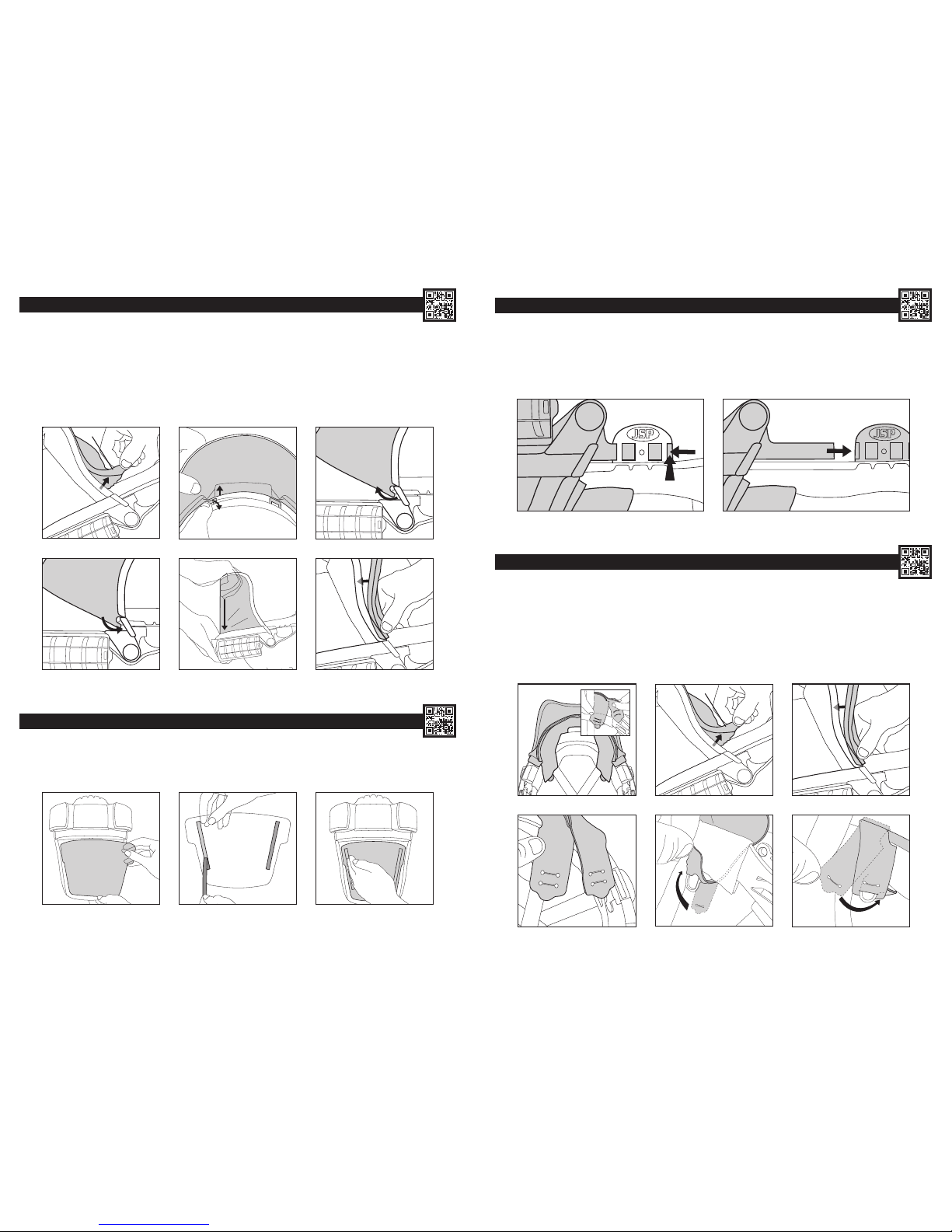
REMOVING & REPLACING THE HARNESS STRAP:
1. Unhook the four inner and outer face-seal skirt loops from the harness mounting points inside the helmet.
2. Remove the harness strap by un-popping the arm from the receiver (hold the helmet and receiver rmly whilst doing so).
3. Repeat this process for all 4 arms then take the harness strap out from the helmet. Dispose of used strap in accordance with local legislation.
4. Place the replacement strap inside the helmet shell, then pop the rst arm back into position and repeat the process for all 4 arms.
5. Feed the outer set of skirt loops behind the harness strap inside the helmet. Hook the loops over the harness mounting points inside the helmet.
6. Hook the inner set of skirt loops over the harness mounting point and outer loops. Repeat with the loops on the other end of the sealing skirt.
SKIRT LOOPS
ADDITIONAL INDUSTRIAL SAFETY HELMET INSTRUCTIONS:
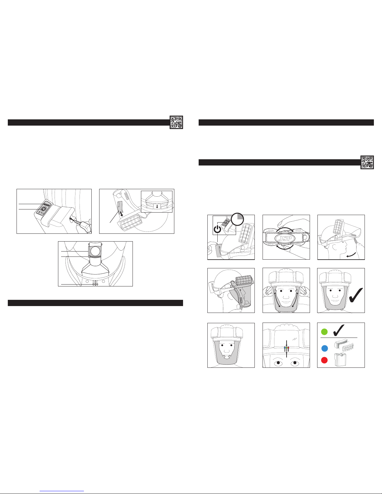
Fitting and adjustment: Fit the helmet as described in the PowerCap® Innity®Donning section of this manual. For adequate protection PowerCap®
Innity® must t or be adjusted to the size of the user’s head.
Use: The helmet is made to absorb the energy of an impact by partial destruction or damage to the shell or harness and even though such damage
may not be readily apparent, any helmet subjected to severe impact should be replaced. This helmet has been designed to protect the wearer against
electrical shocks by preventing passage of dangerous current through the body via the head. The helmet must be used with other insulating protective
equipment when working on low voltage installations. The user should check that the electrical limits of the helmets correspond to the nominal voltage that
is likely to be encountered during use. Accessories and/or replacement components are available with tting instructions from JSP.
Inspection and care of the helmet: The helmet is a complete system consisting of shell and harness. The helmet’s useful life is affected by many
factors including the cold, heat, chemicals, sunlight and misuse. The helmet should be examined daily for obvious signs of cracking, brittleness or
damage to either helmet or harness. The user should be aware that there is potential risk of loss of protection due to ageing and/or inappropriate
cleaning. The effectiveness of the insulating properties of the helmet may be affected by the conditions of use. The date of manufacture is moulded into
the peak of the helmet. While the helmet is free from defects it is suitable for its intended purpose. If in any doubt destroy the helmet.
Useful life: Under normal circumstances the helmet has a maximum life of 5 years from date of manufacture. Under no circumstances must a
component other than a JSP component be used on a helmet.
MARKINGS:
ADDITIONAL INDUSTRIAL EYE PROTECTION INSTRUCTIONS:
Assembly: The PowerCap® Innity® visor should be tted to, and used with the PowerCap® Innity® visor carrier and helmet, see tting instructions in
the Removing & Replacing the Visor section of this manual.
Useful life: Under normal circumstances the visor should offer protection for up to 5 years. Scratched or damaged visors should be replaced.
Replacement visors are available.
MARK MEANING
EN12941:---- European standard for powered ltering respiratory
devices and its year of publication
A#:---- Amendment to EN12941 and its year of publication
TH3 Indicates a 99.8% efciency with an APF 40
R SL A reusable solid and liquid aerosol lter
EN397:---- The European standard number for industrial
safety helmets and its year of publication
EN50365:----
The European standard number for electrically
insulating helmets for use on low voltage
installations and its year of publication
The double triangle symbol means that this helmet
is electrically insulated for use working live or
close to live parts on installations not exceeding
1000Vac or 1500Vdc
53-63 cm The size range of the helmet, head circumference
-20°C / -30°C /
-40°C
The helmet will provide some protection when
worn in an environment at or above these
temperatures
MM The helmet will provide some protection against
molten metal splash
440 Vac
The helmet will protect the user against short term,
accidental contact with live electrical conductors
up to a voltage of 440 Vac
LD The helmet will provide some protection from
lateral compressive loads
MARK MEANING
EN166:2002 European standard for protective eyewear
2-1.2 Shade number
1Optical quality (high)
BProtection against medium energy impact against
high speed particles
8Protection against short circuit electric arc
9Protection against molten metals and hot solids
KResistance to surface damage by ne particles
See instructions for use. If the instructions for use
recommendations are not adhered to, the protection
afforded by the device may be severely impaired.
Storage temperature and humidity ranges
Indicates that product conforms to relevant EU
Directives and Regulations regarding health and
safety or environmental protection
Dispose of in accordance with local legislation
Some of the components of the device can be
recycled
Date of manufacture
Use by date

14 15
ACCESSORIES:
Hearing protection can be added to the Powercap® Innity® by tting the Sonis® helmet mounted ear defenders. The Sonis® range of helmet mounted
ear defenders and the Powercap® Innity® have been designed to be compatible.
Fitting the Sonis®:
Remove the PowerCap® Innity®visor complete with the PowerCap® Innity®drive unit & visor carrier assembly. Unhook the sealing skirt from
the harness (see Removing & Replacing the Visor) and disconnect the power cable from the battery box (see Battery and Airow Check). To remove
the visor carrier, press the rear of the visor side arms towards the helmet shell and push forwards. (see Removing & Replacing the Drive Unit and Visor
Carrier Assembly).
1. Remove the visor carrier adaptors from the helmet shell. Inverting the helmet, push the adaptor blade towards the outside of the helmet and then down.
Then use a thin sharp object such as a screwdriver to push the release button on the outside of the helmet shell.
2. Fit the ear defender as the instructions supplied with the ear defender of your choice.
3. Once the ear defenders are tted, slide the visor side arms into the slot on the ear defender helmet adaptor.
• Ensure that the visor skirt is correctly attached as stated in Removing & Replacing the Visor.
• When donning the helmet, adjust the ear defenders as stated in user instructions supplied with the ear defender. Ensure that both the ear
defender and the PowerCap® Innity® are correctly adjusted and comfortable. Failure to do so may result in the levels of protection offered by
either or both units being severely reduced.
WARRANTY:
JSP Ltd warrants to its customers of PowerCap® Innity® that the device will be free from defects in materials and mechanical or electrical defects for a
period of 24 months from date of purchase in accordance with EU Directive 1999/44/EEC. This warranty is subject to:
• PowerCap® Innity® being used solely for the purpose for which it is intended.
• PowerCap® Innity® not being subject to misuse, damage, modication or repair.
• The user must register the product to enact this guarantee.
To register the product, visit www.jspwarranty.com
JSP Ltd will replace defective parts as required at no charge. JSP Ltd’s liability will not exceed the value of the original sales receipt for the device. In the
event of valid claims under this warranty JSP Ltd will not be liable for loss of use of any of its products or for any incidental, indirect or consequential cost,
expenses or damages incurred or claimed by the purchaser or any other user. No other terms are implied by this warranty but a purchaser’s statutory rights
are not affected. To make a claim under this warranty, please contact the retailer from which the PowerCap® Innity® was purchased.
BATTERY INFORMATION:
1 2 3
CLEANING:
The product should only be cleaned with a cloth lightly dampened with a mild detergent solution. Care must be taken to avoid any liquids entering the
motor/fan assembly or the lters.
Battery Type: Lithium-ion 3.6V, 5.2Ah, 18.72 Wh. The battery has an expected life of 500 cycles when charged, stored and used in accordance
with these instructions.
• Operating temperature should be between +5°C and +40°C and relative humidity not greater than 75%.
• The temperature for charging and discharging of the battery should be between +5°C and +40°C.
• Do not dismantle, open or shred the battery pack.
• Do not expose the battery pack to heat, re or microwaves. Avoid storage in direct sunlight.
• Do not short-circuit the battery pack. Do not place the battery pack haphazardly in a box or drawer where it may short-circuit with another or be short-
circuited by other metal objects?
• Do not remove the battery pack from its original packaging until required for use.
• Do not subject the battery pack to mechanical shock.
• In the event of the battery pack leaking, do not allow the liquid to come in contact with the skin or eyes. If contact has been made, wash the affected
area with copious amounts of water and seek medical advice.
• Do not use any charger other than that specically provided for use with the PowerCap® Innity®.
• Do not use any cells or batteries which are not designed for use with the PowerCap® Innity®.
• PowerCap® Innity® is not intended to be used by children, children should not be left unsupervised with PowerCap® Innity® or its battery pack.
• Seek medical advice immediately if parts of a dismantled battery pack have been swallowed.
• Only replacement battery packs intended for the PowerCap® Innity® are recommended by JSP Ltd for use with PowerCap® Innity®.
• Keep the battery pack clean and dry.
• Wipe the battery pack terminals with a clean dry cloth if they become dirty.
• The PowerCap® Innity® battery pack needs to be charged before use. Always use the correct charger supplied with PowerCap® Innity®and refer to
the user instructions for the correct charging procedure.
• Do not leave a battery pack on prolonged charge when not in use.
• After extended periods of storage, it may be necessary to charge and discharge the battery pack several times to obtain maximum performance.
• Retain the original user instructions for future reference.
• The battery pack is only intended for use with the PowerCap® Innity®, it is not suitable for any other application.
• When possible, remove the battery pack from the equipment when not in use.
• Dispose of exhausted battery packs in accordance with local legislation.

REPLACEMENT PARTS:
REPLACEMENT
PARTS
PRODUCT
CODE IMAGE REPLACEMENT
PARTS
PRODUCT
CODE IMAGE
PowerCap® Innity®
Filters (Pair) CAU660-000-400
PowerCap® Innity®
Twin-Turbo Drive
Unit and Visor
Carrier Assembly
CEU120-001-300
PowerCap® Innity®
Pre-Filter (5 Pairs)
and Pre-Filter
Covers
CEU100-006-500 PowerCap® Innity®
Battery Pack CEU170-000-000
PowerCap® Innity®
Nuisance Odour
Pre-Filters (5 Pairs)
and Covers
CEU160-000-000 PowerCap® Innity®
Visor Seal CEU180-000-000
PowerCap®
Innity® Visor CEU110-001-300
PowerCap® Innity®
Charge Dock and
Power Supply
CEU130-001-100
PowerCap® Innity®
Peel Off Visor
Protectors
(10 pack)
CAU180-000-000
PowerCap® Innity®
Airow Indicator
Test Unit
CEU140-001-100
Black*
EVO®5 Helmet for
PowerCap® Innity®
*Other colours
available on request
AKG179-P01-100 PowerCap® Innity®
Carry-Case CEU170-001-100
Helmet Harness
Strap CEU190-000-000
16
JSP Ltd, Worsham Mill, Minster Lovell Oxfordshire, OX29 0TA
Technical Helpline: +44(0)1993 826051
Email: technicalservices@jspsafety.com www.jspsafety.com
Certied by: BSI (NB0086).
BSI UK, Kitemark Court, Davy Avenue, Knowlhill,
Milton Keynes, MK5 8PP. United Kingdom
ISSUED: 02/18
RFPZ-001-000
Other manuals for Powercap Infinity
1
Table of contents
Other JSP Respiratory Product manuals

JSP
JSP AFP-25 User manual

JSP
JSP 51 45 80 User manual

JSP
JSP JETSTREAM Operator's manual

JSP
JSP POWERCAP ACTIVE Lite Operator's manual

JSP
JSP AVENGER N-AF-KIT User manual

JSP
JSP AVENGER AIR FED VISOR KIT User manual

JSP
JSP Powercap Infinity User manual

JSP
JSP POWERCAP ACTIVE Series Operator's manual

JSP
JSP SPRINGFIT User manual

JSP
JSP POWERCAP ACTIVE Operator's manual