JTS FGM-170 User manual

www.jts-europe.com
FGM-170
Bestellnummer 0236070
Mikrofon mit Stativ
®
Vertrieb von JTS-Produkten – Distribution of JTS products
MONACOR INTERNATIONAL GmbH & Co. KG, Zum Falsch 36, 28307 Bremen, Germany
Copyright©by MONACOR INTERNATIONAL. All rights reserved. A-2117.99.01.02.2022
DEUTSCH
Diese Anleitung richtet sich an
Benutzer mit Grundkenntnissen
in der Audiotechnik. Bitte lesen
Sie die Anleitung vor dem Betrieb
gründlich durch und heben Sie sie
für ein späteres Nachlesen auf.
1 Einsatzmöglichkeiten
Das FGM-170 mit drei austauschbaren
Back-Elektret-Mikrofonkapseln ist opti-
mal für Sprach- und Gesangsanwendun-
gen (z.B. Chorabnahme) geeignet, lässt
sich aber auch für die Schallabnahme
von Instrumenten einsetzen. Das Boden-
stativ verfügt über ein Teleskoprohr und
einen extrem leichten Carbonfaser-Gal-
gen. Die drei Mikrofonkapseln haben
unterschiedliche Richtcharakteristiken
und benötigen für den Betrieb eine
Phantomspeisung. Eine Pegeldämpfung
und ein Hochpassfilter sind schaltbar.
2 Wichtige Hinweise
Das Produkt entspricht allen relevanten
Richtlinien der EU und trägt deshalb das
-Zeichen.
•
Setzen Sie das Produkt nur im Innen-
bereich ein. Schützen Sie es vor Tropf-
und Spritzwasser sowie hoher Luft-
feuchtigkeit. Der zulässige Einsatz-
temperaturbereich beträgt 0– 40°C.
•
Verwenden Sie für die Reinigung nur
ein trockenes, weiches Tuch, niemals
Wasser oder Chemikalien.
•
Wird das Produkt falsch verwendet
oder nicht fachgerecht repariert,
kann keine Haftung für daraus resul-
tierende Sach- oder Personenschäden
und keine Garantie für das Produkt
übernommen werden.
Soll das Produkt endgültig aus
dem Betrieb genommen wer-
den, entsorgen Sie es gemäß
den örtlichen Vorschriften.
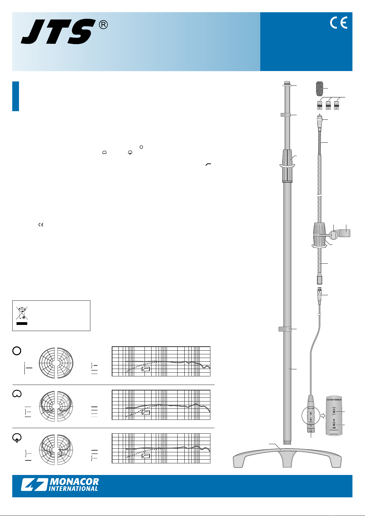
3 Inbetriebnahme
1)
Das Teleskoprohr (4) in den Stativ-
fuß (5) schrauben. Den Gewinde-
kopf(11) der Galgenhalterung auf
das Teleskoprohr schrauben und mit
der Kontermutter (1) fixieren.
2) Bei Auslieferung ist eine der drei Mik-
rofonkapseln (7) bereits auf das obere
Ende des Galgens geschraubt. Ist eine
Kapsel mit einer anderen Richtcha-
rakteristik (☞Symbol auf der Kapsel:
Kugel, Niere, Superniere) ge-
wünscht, diese aus der beiliegenden
Tasche nehmen und sie gegen die
bereits aufgeschraubte austauschen.
3)
Den Mini-XLR-Stecker (14) des Mik-
rofonkabels in die Buchse am unte-
ren Ende des Galgens stecken. (Beim
späteren Herausziehen zum Entriegeln
den schwarzen Knopf am Stecker drü-
cken.) Den XLR-Stecker(17) an einen
Mikrofoneingang des nachfolgenden
Geräts (z.B. Mischpult, Vorverstärker)
anschließen. Der Mikrofoneingang
muss eine Phantomspeisung im Be-
reich von 12– 48 V bereitstellen. Ist
dies nicht der Fall, das Mikrofon über
ein entsprechendes Phantomspeise-
gerät an den Eingang anschließen.
Als Betriebsanzeige* leuchtet der rote
Ring(8) am Mikrofon.
4)
Zur Höheneinstellung des Teleskop-
rohrs die Spannmuffe (3) durch Drehen
lösen, das Rohr auf die gewünschte
Länge ausziehen und die Muffe wie-
der festdrehen. Zur Höheneinstellung
des Galgens die Spannmuffe (12)
lösen, das Galgen-Rohr(13) lässt sich
jetzt in der Halterung verschieben. Da-
nach die Muffe wieder festdrehen. Die
Neigung des Galgens kann nach dem
Lösen der Feststellschraube (10) geän-
dert werden. Die Feinausrichtung des
Mikrofons durch Biegen des Schwa-
nenhalses(9) vornehmen.
5) Das Kabel lässt sich mit den Klemm-
ringen (2) am Teleskoprohr fixieren.
6)
Um Windgeräusche zu verringern,
z.B. beim nahen Sprechen in das Mi-
krofon oder bei der Nahabnahme von
Blasinstrumenten, den Windschutz(6)
auf die Mikrofonkapsel stecken. Die-
ser schützt die Kapsel auch vor Feuch-
tigkeit aus der Atemluft.
7) Die zwei Schalter am XLR-Stecker mit
einem spitzen Gegenstand in die ge-
wünschte Position stellen:
Steht der obere Schalter (15) in Po-
sition , ist das Hochpassfilter (zur
Unterdrückung tieffrequenter Störun-
gen wie z.B. Trittschall) eingeschaltet.
Steht der untere Schalter (16) in
Position „−10“, wird der Signalpe-
gel des Mikrofons um 10dB abge-
schwächt.
4 Technische Daten
Systeme:. . . . . . . . . . Back-Elektret
Richtcharakteristiken: Kugel, Niere,
Superniere
☞Diagramme
Frequenzgang, Filter: ☞Diagramme
Empfindlichkeit: . . . . 15,8 mV/Pa
Nennimpedanz: . . . .220Ω
Max. Schalldruck: . . . 125dB
Stromversorgung: . . . Phantomspeisung
⎓12– 48V*
Mikrofonkabel: . . . . . 8 m, 3-poliger
Mini-XLR-Stecker
auf XLR-Stecker
Galgenlänge: . . . . . . 146 cm
Stativhöhe: . . . . . . . . 90 –160 cm
Gewicht:. . . . . . . . . . 3,6 kg
Änderungen vorbehalten.
1
2
3
4
2
5
20 100 200 500 1k 2k 5k 10k 20kHz
-10
+10
[dB]
0
20 100 200 500 1k 2k 5k 10k 20kHz
-10
+10
[dB]
0
125 Hz
250 Hz
500 Hz
1000 Hz
90°
120°120°
30°
60°60°
30°
90°
150° 150°
2 kHz
4 kHz
8 kHz
16 kHz
180°
0°
25
dB
20
15
10
5
0
20 100 200 500 1k 2k 5k 10k 20kHz
-10
+10
[dB]
0
90°
120°120°
30°
60°60°
30°
90°
150° 150°
125 Hz
250 Hz
500 Hz
1000 Hz
2 kHz
4 kHz
8 kHz
16 kHz
0°
180°
25
dB
20
15
10
5
0
90°
120°120°
30°
60°60°
30°
90°
150° 150°
125 Hz
250 Hz
500 Hz
1000 Hz
2 kHz
4 kHz
8 kHz
16 kHz
0°
180°
25
dB
20
15
10
5
0
15
16
13
14
12
6
7
8
9
10 11
17
*Die Betriebsanzeige ist für eine 48-V-Phan-
tomspeisung ausgelegt.

www.jts-europe.com
®
Vertrieb von JTS-Produkten – Distribution of JTS products
MONACOR INTERNATIONAL GmbH & Co. KG, Zum Falsch 36, 28307 Bremen, Germany
Copyright©by MONACOR INTERNATIONAL. All rights reserved. A-2117.99.01.02.2022
These instructions are intended
for users with basic knowledge
of audio technology. Please read
the instructions carefully prior to
operation and keep them for later
reference.
1 Applications
FGM-170 with three different back elec-
tret microphone capsules is ideal for
speech and vocal applications (e.g. for
picking up sound from a choir), but it
can also be used for picking up sound
from instruments. The floor stand has a
telescopic tube and an extremely light
carbon fibre boom. The three micro-
phone capsules have different polar
patterns and require phantom power
for operation. The microphone offers a
level attenuation switch and a switch to
activate a high-pass filter.
2 Important Notes
The product corresponds to all relevant
directives of the EU and is therefore
marked with .
•
The product is suitable for indoor use
only. Protect it against dripping water,
splash water and high air humidity.
The admissible ambient temperature
range is 0–40 °C.
•
For cleaning only use a dry, soft cloth;
never use water or chemicals.
•
No guarantee claims for the product
and no liability for any resulting per-
sonal damage or material damage will
be accepted if the product is not cor-
rectly used or not expertly repaired.
If the product is to be put
out of operation definitively,
dispose of the product in
accordance with local regu-
lations.
3 Before Operation
1)
Screw the telescopic tube (4) into
the base (5) of the stand. Screw the
threaded head (11) of the boom sup-
port onto the telescopic tube and use
the locking nut (1) to fix it.
2)
When the microphone is delivered,
one of the three microphone cap-
sules(7) is already screwed onto the
upper end of the boom. If a capsule
with a different polar pattern (☞sym-
bol on the capsule: omnidirectional,
cardioid, supercardioid) is re-
quired, take this capsule out of the
bag provided and replace the capsule
screwed on in the factory.
3) Connect the mini XLR connector (14)
of the microphone cable to the socket
at the lower end of the boom. (To re-
move the connector, press the black
button on the connector to unlock it.)
Connect the XLR connector (17) to
a microphone input of the following
device (e.g. mixer, preamplifier). The
microphone input must provide phan-
tom power in the range of 12–48 V.
If this is not the case, connect the mi-
crophone to the input via a suitable
phantom power supply unit. The red
ring (8) on the microphone lights up
as a power indicator*.
4) To adjust the height of the telescopic
tube, turn the clamping sleeve (3) to
loosen the tube, extend the tube to
the desired length and tighten the
sleeve again. To adjust the height
of the boom, loosen the clamping
sleeve(12) so that the boom tube (13)
can be moved in the support. Then
tighten the sleeve again. To change
the inclination of the boom, loosen
the locking screw (10). For fine ad-
justment of the microphone, bend the
gooseneck (9).
5) The clamping rings (2) can be used to
fix the cable to the telescopic tube.
6)
To reduce wind noise, e. g. when
speaking into the microphone at close
range or when picking up sound from
wind instruments at close range, place
the windshield (6) on the microphone
capsule. The windshield will also pro-
tect the capsule from the moisture of
your breath.
7) Use a pointed object to set the two
switches on the XLR connector to the
desired position:
If the upper switch (15) is in
position , the high-pass filter (to
suppress low-frequency noise such as
impact sound) is activated.
If the lower switch (16) is in po-
sition “−10”, the signal level of the
microphone is attenuated by 10dB.
4 Specifications
Systems: . . . . . . . . . . back electret
Polar patterns: . . . . .omnidirectional,
cardioid, super-
cardioid
☞diagrams
Frequency response,
filter:. . . . . . . . . . . . . ☞diagrams
Sensitivity:. . . . . . . . . 15.8mV/Pa
Nominal impedance:. 220Ω
Max. SPL: . . . . . . . . . 125 dB
Power supply: . . . . . phantom power
⎓12– 48V*
Microphone cable: . . 8 m, 3-pole mini
XLR connector to
XLR connector
Length of boom:. . . . 146 cm
Height of stand: . . . . 90 –160cm
Weight: . . . . . . . . . .3.6kg
Subject to technical modification.
FGM-170
Order number 0236070
Microphone with Stand
ENGLISH
20 100 200 500 1k 2k 5k 10k 20kHz
-10
+10
[dB]
0
20 100 200 500 1k 2k 5k 10k 20kHz
-10
+10
[dB]
0
125 Hz
250 Hz
500 Hz
1000 Hz
90°
120°120°
30°
60°60°
30°
90°
150° 150°
2 kHz
4 kHz
8 kHz
16 kHz
180°
0°
25
dB
20
15
10
5
0
20 100 200 500 1k 2k 5k 10k 20kHz
-10
+10
[dB]
0
90°
120°120°
30°
60°60°
30°
90°
150° 150°
125 Hz
250 Hz
500 Hz
1000 Hz
2 kHz
4 kHz
8 kHz
16 kHz
0°
180°
25
dB
20
15
10
5
0
90°
120°120°
30°
60°60°
30°
90°
150° 150°
125 Hz
250 Hz
500 Hz
1000 Hz
2 kHz
4 kHz
8 kHz
16 kHz
0°
180°
25
dB
20
15
10
5
0
1
2
3
4
2
5
15
16
13
14
12
6
7
8
9
10 11
17
*The power indicator is designed for a 48 V
phantom power supply.
This manual suits for next models
1
Table of contents
Languages:
Other JTS Microphone manuals
Popular Microphone manuals by other brands

RODE Microphones
RODE Microphones NT4 instruction manual

SMK-Link
SMK-Link VP3421 GoSpeak! Pro user guide

Valcom
Valcom V-450 installation instructions

Sennheiser
Sennheiser EvolutionWireless EW 300 Series instruction manual

Standard Horizon
Standard Horizon SSM-71H manual

Stage Line electronic
Stage Line electronic ECM-310W quick start guide