JTS UF-20R User manual

Professional Wideband (75MHz)
True Diversity System
No.148, 9th Industry Road, Ta-Li Industrial
Park, Taichung City 41280, Taiwan (R.O.C.)
Tel: 886-4-24938803 Fax: 886-4-24914890
Email: [email protected]
PROFESSIONAL CO., LTD
www.jts.com.tw
Product manual
UF-20R / UF-20S /
JSS-20 / UF-20TB
59508-072-02
UF-20R / UF-20S / JSS-20 / UF-20TB

1. System operation instructions
2. Features
2-1 Receiver// UF-20R/UF-20S
2-2 Handheld Transmitter // JSS-20
2-3 Body-Pack Transmitter // UF-20TB
3. Specication
3-1 Receiver// UF-20R/UF-20S
3-2 Handheld Transmitter // JSS-20
3-3 Body-Pack Transmitter // UF-20TB
3-4 Charger For JSS-20 & UF-20TB & PS-20
3-5 Optional Condenser Microphone
4. Parts Identication & Accessories
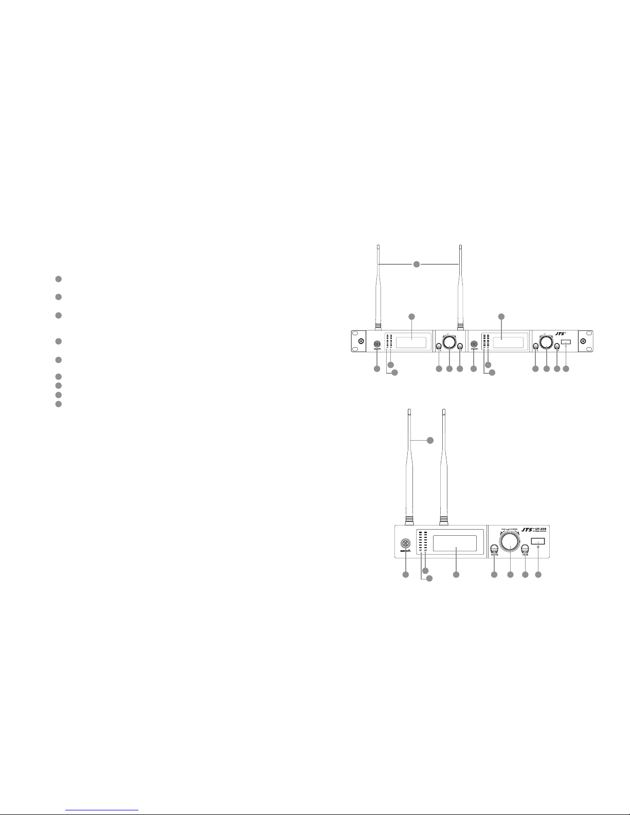
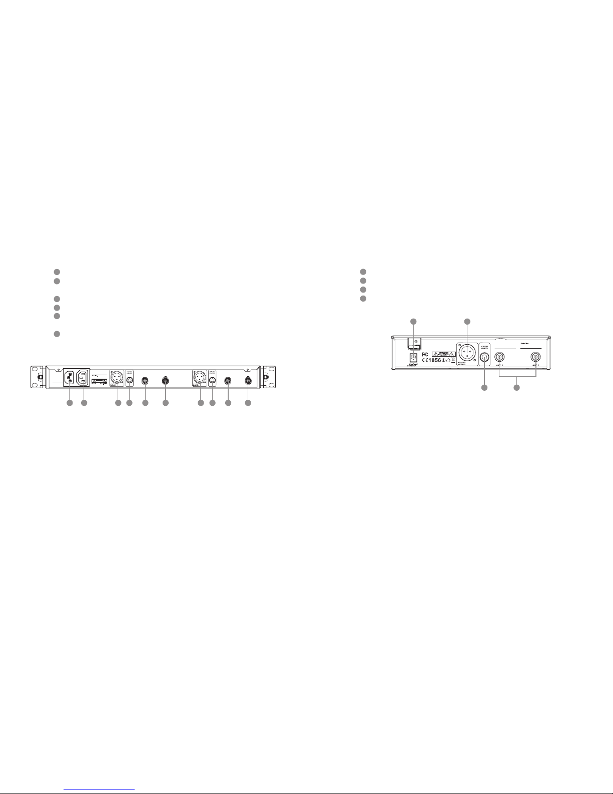
4-1 Receiver // UF-20R/UF-20S
4-2 Handheld Transmitter // JSS-20
4-3 Body-Pack Transmitter // UF-20TB
4-4 Optional 2-Slot Charger / 8-Slot Charger // CH-2/CH-8
4-5 Optional Condenser Microphone
4-6 Accessories
5. Connection method
6. Operation
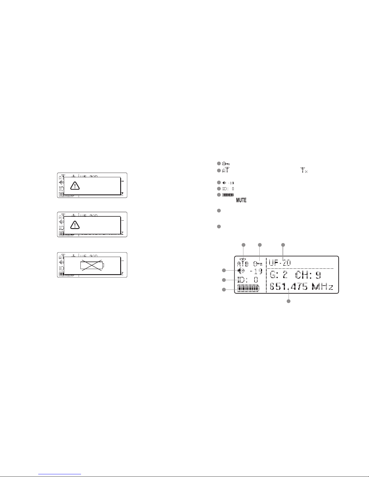
6-1 Receiver// UF-20R/UF-20S
6-2 Handheld Transmitter // JSS-20
6-3 Body-Pack Transmitter // UF-20TB
6-4 Installation of Condenser Microphones
7. Product notes
8. Important Notice
....................................... 1
............................................................................................. 1
............................................................... 1
....................................................... 2
................................................... 2
................................................................................. 3
............................................................... 3
....................................................... 5
................................................... 5
........................................ 6
..................................................... 6
.......................... 9
.............................................................. 9
...................................................... 15
................................................. 17
.................. 19
..................................................... 20
.................................................................................... 24
............................................................. 26
..................................................................................... 29
............................................................. 29
..................................................... 41
................................................ 47
......................................... 53
............................................................................. 55
................................................................... 56
INDEX
One year product warranty
Product Model
Warranty description
1. Be sure to put the warranty label indicating purchase date on the boom of equipment to ensure your
interest in maintenance and service.
2. Product warranty, starting on the purchase date indicated on “warranty label”, will last for one year; if
the equipment does not have “warranty label”, the warranty period is 15 months from the manufac-
turing date. If a microphone is broken but not sent back with the equipment, the warranty period is
15 months from the manufacturing date of the microphone.
3. Within the warranty period, if the equipment is broken under normal use as instructed in manual,
please contact the original selling store for repair.
4. When the product is returned for repair, to facilitate proper determination of cause of malfunction
and of whether repair fee is needed, please ship back the equipment and microphone together.
5. Within the warranty period, our company provides repair service at no cost except for the following
conditions that parts and repair may be charged:
a.Damages due to natural disaster or irresistible outside forces.
b.Damages due to drop, water, moisture, corrosion, foreign objects, missing components.
c.e warranty does not cover consumable parts. (such as microphone capsule, ball grille etc.)
d.ose without “warranty label” on equipment or with “warranty label” being damaged and failing to
identify warranty period.
6. Please keep the warranty properly. No replacement will be made if the warranty is missing.
Equipment
serial number
Customer
name
Contact
number
Address
Purchase date
Selling store
stamp
Be sure to put store stamp and ll in purchase date for the warranty to be
effective!

Professional Wideband True Diversity System (75MHz)
12
1. System operation instructions
2. Features
• Before connecting to power, make sure the voltage marked on equipment is the same as that
on the power socket.
• Do not place the equipment in damp and hot environment.
• Prior to operation, please dry your hands.
• Keep the equipment away from re and heat source.
• Transmier and receiver need to be adjusted to the same “default channel” or “frequency”.
• 2400 to 3000 selectable frequencies
• Preset 15 groups each of up to 63 compatible channels
• Phase-Locked Loop (PLL) synthesized tune
• Extended dynamic range and smooth frequency response.
• Adjustable transmission power between Low and High
• e panel Lock-On function prevents tampering and RF interruption
NEWEST FEATURE:
• Low cut function.
• JTS newest development SAM-8WLN capsule assures outstanding acoustic performance
while minimizes touching noise.
• Interchangeable capsule design for various choices including some classic capsule modules.
• It is designed with slot-in charging feature with two AA NiMH rechargeable baeries.
• 2400 to 3000 selectable frequencies
• Preset 15 groups each of up to 63 compatible channels
• Phase-Locked Loop (PLL) synthesized tune
• Extended dynamic range and smooth frequency response.
• Adjustable transmission power between Low and High
• e panel Lock-On function prevents tampering and RF interruption
• Together with JTS various music instrument mics, headset mics and tie clip mics this bodypack
is versatile for all applications.
NEWEST FEATURE:
• It is designed with slot-in charging feature with two AA NiMH rechargeable baeries.
2-2 UHF PLL Handheld Transmitter // JSS-20
2-3 UHF PLL Body-Pack Transmitter // UF-20TB
• UHF true diversity technology renders 200-480 meters of operation distance
• Maximum 2400 to 3000 selectable frequencies across 60 to 75 MHz
• Preset 15 groups each of up to 63 compatible channels
• User programmable 6 groups each of 64 channels
• Free space scan function
• JTS Patented obstacle-free RF function synchronizes a transmier by pushing
a buon
• JTS LCX circuit design technology minimizes Companding noise
NEWEST FEATURE:
• e now sends not only the frequency data but also transmier’s RF power,
sensitivity, low cut, key lock and user’s name.
• RF “NO SIGNAL” alert function.
• AF “MUTE” alert function.
• Transmier “LOW BAERY” alert function.
• Built in equalizer
• Power / Antenna cascading output provided. (UF-20R Only)
2-1 UHF PLL Wideband True Diversity Receiver // UF-20R/UF-20S
REMOSET
REMOSET

Professional Wideband True Diversity System (75MHz)
34
3. Specication
3-1-1. Dual Channel Wideband True Diversity Receiver // UF-20R
Frequency Preparation...............
Frequency Seing..........................
Carrier Frequency Range.........
Channel................................................
Bandwidth..........................................
S/N Ratio............................................
T.H.D. ....................................................
Chassis...................................................
Preset Channels / Group.........
Display...................................................
Display Contents...........................
Sensitivity.............................................
Receiving Mode..............................
Audio Output Level.....................
XLR AF Output Impedance
Frequency Response...................
Squelch..................................................
Power Supply.....................................
Output Connector........................
Dimension(mm)...........................
PLL Synthesized Control
JTS patented obstacles-free RF REMOSET
UHF 470~960MHz
Dual
60~75MHz Wideband
>108dB(A)
<0.5%@1KHz
1U standard metal chassis
*From group 1 ~ 15 up to 63 interference-free compatible channels.
*844 preset channels/group and 3000 selectable frequencies across
60 to 75 Hz Bandwidth.
*User programmable from U1 ~ U6 each of 64 channels reserved.
LCD and LED
Group, Channel, Frequency, Antenna A/B ,RF/AF Level Meter,
Mute Display, Transmier Baery Status, REMOSET ID Number,
User Name, Squelch
6dBμV, at S/N>80dB
True diversity
Maximum 6dBu
150/600Ω (mic/Line)
50Hz~18kHz, with high-pass lter
Pilot Tone & Noise Mute
100~240V or 12V DC
2 XLR Balanced Socket /
2 Ø6.3mm Balanced phone jack
480mm(W)x45Mmm(H)x260mm(D)
3-1-2. Single Channel Wideband True Diversity Receiver // UF-20S
Frequency Preparation...............
Frequency Seing..........................
Carrier Frequency Range.........
Channel................................................
Bandwidth..........................................
S/N Ratio............................................
T.H.D. ....................................................
Chassis...................................................
Preset Channels / Group.........
Display...................................................
Display Contents...........................
Sensitivity.............................................
Receiving Mode..............................
Audio Output Level.....................
XLR AF Output Impedance
Frequency Response...................
Squelch..................................................
Power Supply.....................................
Output Connector........................
Dimension(mm)...........................
PLL Synthesized Control
JTS patented obstacles-free RF REMOSET
UHF 470~960MHz
Single
60~75MHz Wideband
>108dB(A)
<0.5%@1KHz
1/2U standard metal chassis
*From group 1 ~ 15 up to 63 interference-free compatible channels.
*844 preset channels/group and 3000 selectable frequencies across
60 to 75 Hz Bandwidth.
*User programmable from U1 ~ U6 each of 64 channels reserved.
LCD and LED
Group, Channel, Frequency, Antenna A/B ,RF/AF Level Meter,
Mute Display, Transmier Baery Status, REMOSET ID Number,
User Name, Squelch
6dBμV, at S/N>80dB
True diversity
Maximum 6dBu
150/600Ω (mic/Line)
50Hz~18kHz, with high-pass lter
Pilot Tone & Noise Mute
100~240V or 12V DC
1 XLR Balanced Socket /
1 Ø6.3mm Balanced phone jack
212mm(W)x44Mmm(H)x 213.9mm(D)

Professional Wideband True Diversity System (75MHz)
56
3-2 Professional Wideband Handheld Transmitter // JSS-20
Frequency Preparation...............
Carrier Frequency Range.........
Bandwidth..........................................
RF Outputs........................................
Stability..................................................
Frequency Deviation...................
LCD Display......................................
Controls................................................
Spurious Emissions......................
Audio Frequency Response....
Capsule Module.............................
Baery....................................................
Dimension(mm)............................
Weight....................................................
PLL Synthesized Control
UHF 470~960 MHz
60~75MHz Wideband
Low / High
<±10KHz
±48KHz (Peak)
Group, Channel, Frequency, Battery Status, User Name,
GAIN Adjust
Power ON/OFF, AF Level, Frequency (Up/Down), Lock-on
Mode, REMOSET ID, RF Output Adjust
<-50 dBC
50Hz~18k Hz
Interchangeable
AA NiMH x2
50mm(W)x253mm(H)x35.5mm(D)
350g
Frequency Preparation...............
Carrier Frequency Range.........
Bandwidth..........................................
RF Outputs........................................
Stability..................................................
Frequency Deviation...................
Chassis...................................................
LCD Display.....................................
Controls................................................
Output Connector........................
Spurious Emissions.......................
Audio Frequency Response....
Baery.....................................................
Dimension(mm)............................
Weight....................................................
PLL Synthesized Control
UHF 470~960 MHz
60~75MHz Wideband
Low / High
<±10KHz
±48KHz (Peak)
Aluminium alloy
Group, Channel, Frequency, Battery Status, User Name ,
GAIN Adjust
Power ON/OFF, AF Level, Frequency (Up/Down), Lock-on
Mode, REMOSET ID, RF Output Adjust
4P Mini XLR
<-50 dBC
50Hz~18k Hz
AA NiMH x2
62mm(W)x80.3mm(H)x22.6mm(D)
93g
3-3 UHF PLL Body-Pack Transmitter // UF-20TB
3-4 Optional Charger For JSS-20 & UF-20TB & PS-20
3-5 Optional Condenser Microphone
Lavaliere Microphone
Model No...............................
Input...........................................
Output......................................
Model No...............................
Input...........................................
Output......................................
CH-2 ( 2-Slot Charger )
AC 100~240V, 0.4A max
DC 12V, 1A
CH-8( 8-Slot Charger )
AC 100~240V, 1.2A max
DC 15V, 3A
Model No...............................
Connector..............................
Frequency Response......
Polar Paern..........................
Sensitivity (at 1000Hz)
Impedance.............................
Max. SPL for 1% THD
Dimension(mm)..............
Net Weight............................
CM-501
4P Mini XLR
100~15,000 Hz
Cardioid
-60±3 dB
2.2kΩ
130dB
Ø10.1mm(W)
* 26.4mm(H)
21.5g
CM-201i
4P Mini XLR
60~15,000 Hz
Omni-directional
-60±3 dB
2.2kΩ
130dB
Ø5mm(W)
* 9mm(H)
20.7g
CM-125i
4P Mini XLR
50~18,000 Hz
Omni-directional
-53±3 dB
4.4kΩ
130dB
Ø4mm(W)
* 11mm(H)
7g (cable excluded)

Professional Wideband True Diversity System (75MHz)
78
Headset Microphone
Model No...............................
Connector...............................
Frequency Response......
Polar Paern..........................
Sensitivity (at 1000Hz)
Impedance.............................
Max. SPL for 1% THD
Dimension(mm)..............
Net Weight............................
CM-235i
801C4
(4P Mini XLR)
50~18,000 Hz
Omni-directional
-53±3 dB
1.8kΩ
130dB
155mm(W)
* 134mm(H)
* 157mm(D)
17g (cable excluded)
CX-504
4P Mini XLR
30~18,000 Hz
Cardioid
-68±3 dB
680Ω
130dB
285mm(W)
* 55mm(H)
* 111.3mm(D)
56.3g
Model No...............................
Connector...............................
Frequency Response......
Polar Paern..........................
Sensitivity (at 1000Hz)
Impedance.............................
Max. SPL for 1% THD
Dimension(mm)..............
Net Weight............................
CM-214i
801C4
(4P Mini XLR)
60~15,000 Hz
Omni-directional
-60±3 dB
1.8kΩ
130dB
125mm(W)
* 134mm(H)
* 157mm(D)
32.9g
CM-214Ui
801C4
(4P Mini XLR)
30~18,000 Hz
Cardioid
-68±3 dB
680Ω
130dB
205mm(W)
* 134mm(H)
* 157mm(D)
38.4g
CM-214ULi
801C4
(4P Mini XLR)
100 ~ 18,000Hz
Cardioid
-65±3 dB
1.8kΩ
120dB
125mm(W)
* 134mm(H)
* 157mm(D)
18g (cable excluded)
Ear-hook Microphone
Model No...............................
Connector..............................
Frequency Response......
Polar Paern..........................
Sensitivity (at 1000Hz)
Impedance.............................
Max. SPL for 1% THD
Good For.................................
Model No...............................
Connector..............................
Frequency Response......
Polar Paern..........................
Sensitivity (at 1000Hz)
Impedance.............................
Max. SPL for 1% THD
Good For.................................
CX-500
4P Mini XLR
20~20,000 Hz
Omni-directional
-58±3dB
1.5kΩ
130 dB
Violin
CX-508W
4P Mini XLR
50~18,000 Hz
Cardioid
-67±3 dB
220Ω
130 dB
Winds
CX-500F
4P Mini XLR
20~20,000 Hz
Omni-directional
-58±3dB
1.5kΩ
130 dB
Flutes
CX-520
4P Mini XLR
50~16,500 Hz
Supercardioid
-78±3dB
600Ω
148 dB
Harmonica
CX-516W
4P Mini XLR
30~18,000 Hz
Cardioid
-67±3 dB
220Ω
130 dB
Accordion
Compatible Instrument Microphone
Model No...............................
Connector..............................
Frequency Response......
Polar Paern..........................
Sensitivity (at 1000Hz)
Impedance.............................
Max. SPL for 1% THD
CM-801/CM-804i
801C4 (4P Mini XLR)
60~15,000 Hz
Omni-directional
-64±3 dB
1.8kΩ
130dB
CM-8015/CM-825i
801C4 (4P Mini XLR)
50~18,000 Hz
Omni-directional
-53±3 dB
1.8kΩ
130dB

Professional Wideband True Diversity System (75MHz)
910
4. Parts Identication & Accessories
4-1 Buttons and LCD Displays of Wideband True Diversity Receiver//
UF-20R/UF-20S
Power : Power on: Push the Power buon to turn on
Power o: Push and hold the Power buon until “Power O ” shows on the LCD
EXIT key: Push EXIT to cancel the selection and exit the menu when the UF-20R is in
the “Seing Menu.”
Rotary switch: When in the “Function Seing Menu,” the rotary switch allows the selec-
tion of the desired functions up and down; push the rotary switch (or the SETUP) to enter
the selection, rotate the switch to select the desired seing and push SETUP to save it.
SETUP: Push and hold for 2 seconds to enter the “Seing Menu;” when the selection and
seing is done with [3. Rotary Switch], push SETUP to save the seing.
REMOSET: When the seing is done on the receiver, push REMOSET to transmit the
seings to the handheld or body-pack transmier.
LCD display: See [4-1-2. Description of receiver LCD display].
AF indication: shows the strength of current audio signal.
RF indication: shows the strength of current radio signal.
Antenna
1
4
7
2
5
8
3
6
9
(1) Front panel
UF-20R
UF-20S
EXITSETUP
PUSH / CONTROL
EXITSETUP
PUSH / CONTROL
UF-20R
wireless receiver
3 34 42 2 1
6 6
5 5
7 7
8 8
9
3 2 146
7
8
5
9

Professional Wideband True Diversity System (75MHz)
11 12
4-1-2. Description of receiver LCD display
Display color:
Red: (1) No RF signal is received from any transmier, and the LCD shows:
(2) Transmier on mute.
(3) Transmier baery low.
Orange: RF and AF signals are received from transmiers.
No Signal
Mic Mute
15
10 1611
12
13
14
15
16
11
12
13
14
10 : Panel Lock On activated on receiver.
: It indicates antenna A or B is receiving signal; is shown when no signal is
received from a microphone.
: receiver volume.
: device ID: from 0 to 255.
: transmier baery level
is shown when no signal is received from transmier or the transmier
is mute.
G: the current group in use; from 1 to 15
CH: the current channel in use, up to 63
Frequency: the current frequency in use
User’s Name (dened in the username seing in the menu)

Professional Wideband True Diversity System (75MHz)
13 14
POWER: AC power, 100 ~ 240VAC
AC power outlet(for cascading): it allows power connection to next receiver with an
extension AC power cable.
AF OUTPUT BALANCED: XLR balanced audio output jack
AF OUTPUT BALANCED: Ø6.3mm balanced audio output jack
Antenna A (or B) In: antenna input (or antenna booster jack + 12VDC/150mA); it con-
nects to antenna or antenna booster through a BNC signal cable.
RF A (or B) Out: RF signal output socket(for cascading): Provide RF signal to next
receiver.
18
17
19
4-1-3. Back panel // UF-20R
RF A Out 12V out
Antenna A In
12V out
Antenna B In
RF B Out
Freq.Range:
1856
Made in Taiwan
RISKOF ELECTRIC SHOCK
DONOT OPEN
CAUTION
POWER
100V~240VAC~
50/60Hz, 2A
191917 18 2020 2222 2121
20
21
22
4-1-4. Back panel // UF-20S
12V
Freq.Range:
Made in Taiwan
23
24
25
26
23 24
Power receptacle: connect to power supply (DC12V/1000mA)
Balanced XLR MIC output
Ø6.3mm balanced output
BNC antenna socket: ANT 1 and ANT 2, set antennas vertical or sloping for beer
reception.
25 26

Professional Wideband True Diversity System (75MHz)
15 16
4-2-1. Panel functions
4-2 Buttons and LCD Displays of UHF PLL Handheld Transmitter //
JSS-20
LCD display
SET: set and save handheld transmier
、: up and down buons to select the desired function of the handheld device.
Power
(1) Handheld transmier on
Power on: push the Power buon.
Power o: push and hold the power buon for one second till the display shows
“Power O.”
(2) Mute: the handheld transmier is in use (with main screen on display)
To mute: Short push the power buon display “to activate mute.”
To cancel: Short push the power buon display again “to deactivate mute.”
(3) Exit Seing Menu:
Already in the Seing Menu: push the power buon to return to main screen.
Already in a function seing: push the power buon to return to the Seing Menu
and again to return to the main screen.
Baery tray
Recharging jack: for power charging.(Charger is optional)
Slide cover
Ball grille
LED status display
Green: power on
Blue: Remoset transmiing (approximately 5 seconds)
Red: baery low
Flashing red: mute
Flashing red/green: baery low and mute
27
28
29
30
31
32
33
34
35
Device ID: from 0 to 255
Sensitivity: -15dB ~ +15dB
Low Cut indication
Transmission Power: Hi (High) and Lo (Low)
User name
Baery level: in 5 levels
G: the group in use, from 1 to 15
CH: the channel in use,
up to 63
Lock On Statue
Frequency: it shows
the RF frequency
ID23
JSS-20
Lo
G: 2 C: 10
687.250 MHz
41
40
42
39 37
43
3638
31
27
34
28
29
30 28
32
33
35
4-2-2. Description of LCD display
36
37
38
39
40
41
42
43

Professional Wideband True Diversity System (75MHz)
17 18
Transmission Power: Hi (High) and Lo (Low)
User Name
Indicate current Group and current Channel
Frequency: it shows the RF frequency
Baery level: in 5 levels
Sensitivity Value
Low Cut indication
Aenuate Indication
Lock On Statue
LCD display
Baery level
Red: baery low; replace baery
REMOSET indicators
Blue: Remoset transmiing (approximately 5 seconds)
Power:
(1)On: push the power buon
O: push and hold the power buon for 2 seconds till the display shows “Power
O.”
(2)Exit Seing Menu: when in the Seing Menu, push the power buon to return to
the main screen.
、: up and down buons for selection
SET: to set and save
Mute: switch to “MUTE” to mute the transmier and the red indicator starts to ash.
Baery tray
UHF PLLTransmitter
-12dB
IDoff
633.875 MHz
G: 1 C: 11
UF-20TB
AT
Hi
-12dB
IDoff
633.875 MHz
G: 1 C: 11
UF-20TB
AT
Hi
44
45
46
47
51
48
49
50
4-3-1. Panel functions
4-3 Buttons and LCD Displays of UHF PLL Body-Pack Transmitter //
UF-20TB
45
47
48
44
46
51
49
50
For screen display and operation please refer to “6-3. System operation setup for
Body-Pack transmier”.
4-3-2. Description of LCD display
52
53
54
55
56
57
58
59
60
-12dB
IDoff
633.875 MHz
G: 1 C: 11
UF-20TB
AT
Hi
53
52
54
60
58 59
55
56
57

Professional Wideband True Diversity System (75MHz)
19 20
R
I
S
K
O
F
E
L
E
C
T
R
I
C
S
H
O
C
K
D
O
N
O
T
O
P
E
N
CAUTIO
N
3
.
3
CH-2 CH-8
61
61
4-4 Optional 2-Slot Charger / 8-Slot Charger // CH-2/CH-8
LED Indicator
Full Charged / Standby:Green
Charging:Flash Green
Fault:Flash Red
*Charging Time:3 hours
61
4-5 Optional Condenser Microphone
Clip
4 Pin Mini XLR
Windscreen
64
64 64 64
63
63
Lavaliere Microphone // CM-501 / CM-201i / CM-125i
CM-501 CM-201i CM-125i
62
62
62 62

Professional Wideband True Diversity System (75MHz)
21 22
Gooseneck
Adjustable headband
Headband
4 Pin Mini XLR
Windscreen
CM-214i CM-214Ui
CM-235i CX-504
66
66 66
66
66
67
68
69
69 69
69
69
69
65
65
65
65
65
65
67
68
CM-214ULi
Standard :
4 Pin Mini XLR
Headset Microphone // CM-214i / CM-214Ui / CM-214ULi / CM-235i /
CX-504
Boom
Adjustable Headband
Adjustable ear hook
Detchable Cable
Cable Clip
Windscreen
4 Pin Mini XLR
Ear-hook Microphone // CM-801 / CM-804i / CM-8015 / CM-825i
75
76
72
74
73
70
71
CM-825i 74
75
70
72
73
71
CM-801
74
75
70
72
73
CM-804i 74
75
70
72
73
71
CM-8015
74
75
70
72
73
76

Professional Wideband True Diversity System (75MHz)
23 24
Compatible Instrument Microphone // CX-500 / CX-500F / CX-520 /
CX-508W / CX-516W
82
Gooseneck
Clip
Bracket
Volume Control
Windscreen
4 Pin Mini XLR
80
81
82
79
78
81
81
77
CX-520
CX-500F
CX-500
CX-516W
77
CX-508W
78
77
81 81
77
79
78
80
4-6-1. Accessories for UF-20R
83 85
84
86 87
89 90
92 93
94
91
88
SELF-MA N
SM-018
SELF-MA N
SM-006
R
I
S
K
O
F
E
L
E
C
T
R
I
C
S
H
O
C
K
D
O
N
O
T
O
P
E
N
CAUTIO
N
3
.
3
PS-20
MADE
INTAIWAN
AC power cable * 1
BNC/BNC RF extension cable for cascading * 2
Front antenna signal cable
Extension AC power cable for series connection * 1
XLR(M)/XLR(F) Audio cable * 2
MA-935 Capsule adaptor
PS-20 rechargeable baery module
CH-2 double-slot charger
CH-8 8-slot charger
Antenna * 2
MH-56 Microphones Holder * 2
Color ID housing * 7
83
84
85
86
87
88
89
90
91
92
93
94
Option
Option
Option
Option
Option

Professional Wideband True Diversity System (75MHz)
25 26
4-6-2. Accessories for UF-20S
95 96 97
99 100
101 102
103
98
95
96
97
98
99
100
101
102
103
AC/DC power adapter * 1:
Switching power adapter
AC IN: AC100~240V/50~60Hz
DC OUT: DC12V/1000 mA
XLR(M)/XLR(F) Audio cable * 1
MA-935 Capsule adaptor
PS-20 rechargeable baery module
CH-2 double-slot charger
CH-8 8-slot charger
Antenna * 2
MH-56 Microphones Holder * 1
Color ID housing * 7
Option
Option
Option
Option
32
5. Connection method
1. UF-20 output to a mixer or an amplier:
Audio cable: XLR or Ø 6.3mm audio cable, one end connects to audio output of UF-20R “AF
OUTPUT BALANCED”, while the other end connects to audio input of a mixer or an ampli-
er.
2. Connect to power
Connect to AC outlet: one end connects to receiver “power input”, while the other end con-
nects to AC power receptacle.
5-1-1. Receiver connection method // UF-20R
Figure 1
Amplier
AC transformer
Power receptacle
Step 2
Step 1
Audio output
Power supply
RF A Out 12V out
AntennaA In
12V out
AntennaB In
RF B Out
Freq.Range:
1856
Made in Taiwan
RISKOFELECTRIC SHOCK
DONOTOPEN
CAUTION
POWER
100V~240VAC~
50/60Hz, 2A
PS-20
MADE
INTAIWAN
R
I
S
K
O
F
E
L
E
C
T
R
I
C
S
H
O
C
K
D
O
N
O
T
O
P
E
N
CAUTIO
N
3
.
3

Professional Wideband True Diversity System (75MHz)
27 28
RF A Out 12V out
Antenna A In
12V out
Antenna B In
RF B Out
Freq.Range:
1856
Made in Taiwan
RISKOF ELECTRIC SHOCK
DONOT OPEN
CAUTION
POWER
100V~240VAC~
50/60Hz, 2A
RF A Out 12V out
Antenna A In
12V out
Antenna B In
RF B Out
Freq.Range:
1856
Made in Taiwan
RISKOF ELECTRIC SHOCK
DONOT OPEN
CAUTION
POWER
100V~240VAC~
50/60Hz, 2A
RF A Out 12V out
Antenna A In
12V out
Antenna B In
RF B Out
Freq.Range:
1856
Made in Taiwan
RISKOF ELECTRIC SHOCK
DONOT OPEN
CAUTION
POWER
100V~240VAC~
50/60Hz, 2A
RF A Out 12V out
Antenna A In
12V out
Antenna B In
RF B Out
Freq.Range:
1856
Made in Taiwan
RISKOF ELECTRIC SHOCK
DONOT OPEN
CAUTION
POWER
100V~240VAC~
50/60Hz, 2A
5-2 Cascading of AC power cable and antenna (UF-20R Only)
Power socket
More UF-20Rs…
10 units
It is allowed to cascade power and antennas for 10 units.
12V
Freq.Range:
Made in Taiwan
1. UF-20S output to a mixer or an amplier:
Audio cable: XLR or Ø 6.3mm audio cable, one end connects to audio output of UF-20S “AF
OUTPUT BALANCED”, while the other end connects to audio input of a mixer or an ampli-
er.
2. Connect to power
Connect to AC/DC adapter: one end connects to receiver “DCV INPUT”, while the other
end connects to AC power receptacle.
32
Figure 1
Amplier
AC/DC transformer
Power receptacle
Step 2
Step 1
Audio output
Power supply
5-1-2. Receiver connection method // UF-20S

Professional Wideband True Diversity System (75MHz)
29 30
6-1 Operation settings for Wideband True Diversity Receiver //
UF-20R/UF-20S
6. Operation
6-1-1. Turn the receiver power on.
6-1-2. REMOSET function:
EXITSETUP
PUSH / CONTROL
UF-20R
wireless receiver
(1) Install the receiver antenna.
(2) Push the power buon to turn
the power on
(3)To turn o: push and hold the power
buon till the display shows
“Power O.”
(1) Push the REMOSET buon and the blue indicator starts to ash, indicating the receiver
is transmiing data (Figure 1).
*When using the REMOSET function of UF-20R, it is recommended to carry out RE-
MOSET one by one. is is to prevent the interference between the REMOSET signals
and the failure of data transmiing.
1
Figure 1
Fig. 2
(2) REMOSET successful: the blue indicator on the transmier is on for 3 seconds and that
on the receiver stops ashing.
(3)REMOSET failed: Check the following when the blue indicator on the receiver ashes in
a slow pace:
1)If the receiver and the transmier are of the same frequency band.
2)e “Remoset Function” on in the function menu of Transmier is “activated;”
3)e “Device ID” is the same on both the receiver and transmier.
4)e transmier baery is low (synchronization is not possible if it is too low).
Notes:
(1)For receiver seings, please see: “6. Device ID” and “7. Microphone Seing” of 6-1
Operation seings for Wideband True Diversity Receiver.
(2)For handheld transmier seings, please see: “5. Device ID” and “6. Remoset
Function” of 6.2 Operation seings for handheld transmier system.
(3)For body-pack transmier seings, please see: “5. Device ID” and “6. Remoset
Function” of 6.3 Operation seings for body-pack transmier system.

Professional Wideband True Diversity System (75MHz)
31 32
Push and hold the SETUP buon for 2 seconds to enter the menu.
(1) Turn the rotary switch clockwise or counterclockwise to select the desired function.
Push the switch (or the SETUP buon) to enter the seing screen. Push EXIT to
return to the main menu if nothing is done.
(2) In the seing screen, turn the rotary switch to the desired value or function, and push
SETUP to save the seing.
(3) EXIT: return to main menu or main screen; no saving or modication of seings is
made; push EXIT once to return to the menu and again to return to the main screen.
1. Frequency : this is to dene the frequency.
(1) Rotate the rotary switch to “1. Frequency ” Push the
rotary switch (or SETUP) to enter the frequency adjust-
ment screen.
(2) Adjust the le three digits of frequency: rotate the
switch [+/-] in steps of 1MHz. Push the rotary switch
to save the selected value.
(3) Adjust the right three digits of frequency: rotate the
switch [+/-] in steps of 0.025MHz:
Push the rotary switch to save the selected value.
Note: you may select to adjust the le or right part of
frequency by pushing the rotary switch.
2. Group/Channel : this is to dene groups and channels.
(1) Rotate the rotary switch to “2. Group/ Channel.” Push
SETUP (or the rotary switch) to enter the seing screen.
6-1-3. Menu setting
1. Frequency
2.Group/Channel
3.User Group
4. Scan
M
E
N
U
Setup Frequency
G: 1 CH: 1
687 .250 MHz
Setup Frequency
G: 1 CH: 1
687 . 250 MHz
1. Frequency
2.Group/Channel
3.User Group
4. Scan
M
E
N
U
(2) Rotate the switch to select a group “G:” from 1 to 15.
Push the rotary switch to save the selected value.
(3) Rotate the switch to select a channel “CH:” from up to
63 channels. Push the rotary switch to save the selected
value.
Note: you may select to adjust the group or channel by
pushing the rotary switch.
3. User Group: groups and channels dened by user
Rotate the rotary switch to “3. User Group.” Push the rotary
switch (or SETUP) to enter the seing screen.
#1. Custom Group: the user is to dene a group
(1) Rotate the rotary switch to “1. Custom Group.” Push the
rotary switch to enter the seing screen.
(2) For “every push” of the rotary switch, the display jumps
from group (G), channel (CH) to frequency (the le
or right three digits): when the frequency shows “---.---
MHz,” it means that this channel (G/CH) is not in use.
(3) Rotate the rotary switch to select the group, channel or
frequency for seing; push SETUP to save the seing.
Setup Group
633.625MHz
G: 2CH: 10
Setup Group
633.625MHz
G: 2 CH: 10
1. Frequency
2.Group/Channel
3.User Group
4. Scan
M
E
N
U
1. Custom Group
2. Clear Group
3. Return
Setup User Group
- - -.- - - MHz
G: U1 CH: 1
- - -.- - - MHz
G: U1 CH: 1
Setup User Group
Setup User Group
G: U1 CH: 1
624.000 MHz
Setup User Group
G: U1 CH: 1
624.025 MHz

Professional Wideband True Diversity System (75MHz)
33 34
1. Custom Group
2. Clear Group
3. Return
#2. Clear Group: delete a group dened by us er
(1) Rotate the rotary switch to “2. Clear Group.” Push the
rotary switch to enter the “Clear Group” screen.
(2) Rotate the rotary switch to select the group to be deleted
and push the rotary switch.
Select “Conrm” and all the channels and frequencies of
that group is returned to “---.---MHz.” Select conrm or
cancel and push the rotary switch.
#3. Return: return to main menu
Rotate the rotary switch to “3. Return,” and push the switch to
return to the main menu.
4. Scan: scan for channels
(1) Rotate the rotary switch to “4. Scan.” Push the rotary switch
(or SETUP) to enter the channel scanning screen.
#1. All Groups: scan all groups
(1) Rotate the rotary switch to “1. All Groups.” Push the rotary
switch (or SETUP) to enter the menu.
(2) Enter the “All Groups” (push EXIT to go back up a level)
and push the rotary switch to scan.
(3) e progress in % is shown on the screen during the scan-
ning. To stop scanning, just push EXIT.
(4) e display goes to the “2. Result List” screen automatically
aer the scanning is completed. User may select the list in
the menu.
e user may view the scan result in the screen. Rotate the
rotary switch to select an available channel. Push SETUP
to save seings.
Group: U1
Rotary to select
Push “Entrer” to clear
Push “Exit” to return
Group “U1” will be cleared
continues?
Yes NO
1. Custom Group
2. Clear Group
3. Return
1. Frequency
2.Group/Channel
3.User Group
4. Scan
M
E
N
U
1. All Groups
2. Result List
3. Current Group
4. Return
Scan All Groups
Press Setup or Enter to
start scan.
Press Exit to quit.
Scan All Groups
Scanning... 2%
#2. Result List: view the scan result list
Rotate the rotary switch to “2. Result List.” Push the rotary
switch and enter the menu screen to view the result. Select an
available channel and push SETUP to save the seings.
#3. Current Group: scan a single group
(1) Rotate the rotary switch to “3. Current Group.” Push the
rotary switch to enter the menu screen.
(2) Push the rotary switch to start scanning a single group.
(3) e display shows OK aer scanning; for “every push” of
the rotary switch, the unit starts to scan the next group.
Select and push SETUP to save the seing. Push EXIT to
go back to the previous level.
#4. Return: return to main menu
Rotate the rotary switch to “4. Return.” Push the rotary switch
to return to the main menu.
5. Squelch: adjust the receiver sensitivity
(1) Rotate the rotary switch to “5. Squelch.” Push the rotary
switch (or SETUP) to enter the adjustment menu.
(2) Rotate the rotary switch to adjust the sensitivity. 0dB is the
standard value. Push SETUP to save the seing. e higher
the value, the lower the receiver sensitivity, and the lower
the value, the higher the receiver sensitivity.
1. All Groups
2. Result List
3. Current Group
4. Return
Scan Result List
G: 1 CH: 1
Open Channel : 48
1. All Groups
2. Result List
3. Current Group
4. Return
Scan Current Group
G: 1 CH:1
Scan Current Group
Press Setup to Save.
G: 1 CH: 1 OK
1. All Groups
2. Result List
3. Current Group
4. Return
5. Squelch
6. Device ID
7. Mic Config
8. Volume
M
E
N
U
Setup Squelch
0

Professional Wideband True Diversity System (75MHz)
35 36
6. Device ID: dene the ID code of device
(1) Rotate the rotary switch to “6. Device ID.” Push the rotary
switch (or SETUP) to enter the ID seing menu.
(2) Rotate the rotary switch to select the ID from 0-255; push
SETUP to save the seing.
is seing determines the use of REMOSET. e receiver
and transmier must have the same “device ID” in order to use
REMOSET.
Note: this is not a problem if the microphone ID is not
activated.
7. Mic Cong: Adjust the REMOSET seing of transmier.
(1) Rotate the rotary switch to “7. Mic Cong.” Push the rotary
switch (or SETUP) to enter the adjustment menu.
(2) Rotate the rotary switch to select the desired item.
(1. Sensitivity
(1) Rotate the rotary switch to “1. Sensitivity.” Push the rotary
switch (or SETUP) to enter the adjustment menu.
Rotate the rotary switch to select and set the value. Push
SETUP to save the seing; range: -15dB - +15dB
(2. Aenuate: it sets the aenuation of microphone input
volume from body-pack transmier.
Rotate the rotary switch to “2. Aenuate.” Push the rotary
switch (or SETUP) to enter the adjustment menu.
Rotate the rotary switch to activate or deactivate.
Push SETUP to save the seing.
Note: this is not supported by handheld transmiers.
5. Squelch
6. Device ID
7. Mic Config
8. Volume
M
E
N
U
Setup Device ID
23 〔0~255〕
5. Squelch
6. Device ID
7. Mic Config
8. Volume
M
E
N
U
1. Sensitivity
2. Attenuate
3. Low Cut
4. RF Power
Mic Sensitivity
0 dB
1. Sensitivity
2. Attenuate
3. Low Cut
4. RF Power
Mic Attenuate
ON
OFF
(3. LowCut: base aenuation
Rotate the rotary switch to “3. LowCut.” Push the rotary
switch (or SETUP) to enter the adjustment menu.
e Low Cut is not set.
Rotate the rotary switch one notch clockwise to select
Low Cut (as shown on the right). Push SETUP to save the
seing.
(4. RF Power: RF frequency
Rotate the rotary switch to “4. RF Power” Push the rotary
switch (or SETUP) to enter the adjustment menu.
Rotate the rotary switch to select RF Power.
High → high RF Power
Low → low RF Power
Push SETUP to save the seing.
(5. KeyLock
Rotate the rotary switch to “5. KeyLock.” Push the rotary
switch (or SETUP) to enter the adjustment menu.
Rotate the rotary switch to select lock or unlock.
Push SETUP to save the seing.
(6. Remoset Cong: to select or unselect REMOSET seings.
(1) Rotate the rotary switch to “6. Remoset Cong.” Push the
rotary switch (or SETUP) to enter the seing menu.
1. Sensitivity
2. Attenuate
3. Low Cut
4. RF Power
Mic Low Cut
Mic Low Cut
1. Sensitivity
2. Attenuate
3. Low Cut
4. RF Power
Mic RF Power
High
Low
4. RF Power
5. Kry Lock
6. Remoset Config
7. Return
Mic KeyLock
Lock ON
Lock OFF
4. RF Power
5. Kry Lock
6. Remoset Config
7. Return
Mic Attenuate
ON
OFF
Other manuals for UF-20R
1
This manual suits for next models
3
Table of contents
Other JTS Microphone manuals