www.jts-europe.com
Cette notice d’utilisation s’adresse
aux utilisateurs sans connais-
sances techniques particulières.
Veuillez lire la présente notice
avec attention avant le fonc-
tionnement et conservez-la pour
pouvoir, si besoin, vous y repor-
ter ultérieurement.
1 Possibilités d’utilisation
Le set de microphones se compose d’un
microphone électret miniature pour instru-
ments, d’un microphone de contact (dans le
socle de fixation) et d’un mixeur qui sert éga-
lement pour l’alimentation des microphones.
Le set est particulièrement bien adapté pour la
prise de son d’instruments à cordes. Le mixeur
est alimenté via l’alimentation fantôme (par
exemple d’une table de mixage) ou via une
batterie 9V insérée. Il permet de mixer le son
des deux micros comme vous le souhaitez. En
mode fonctionnement sur batterie, le signal
de mixage des micros peut être contrôlé via la
sortie casque.
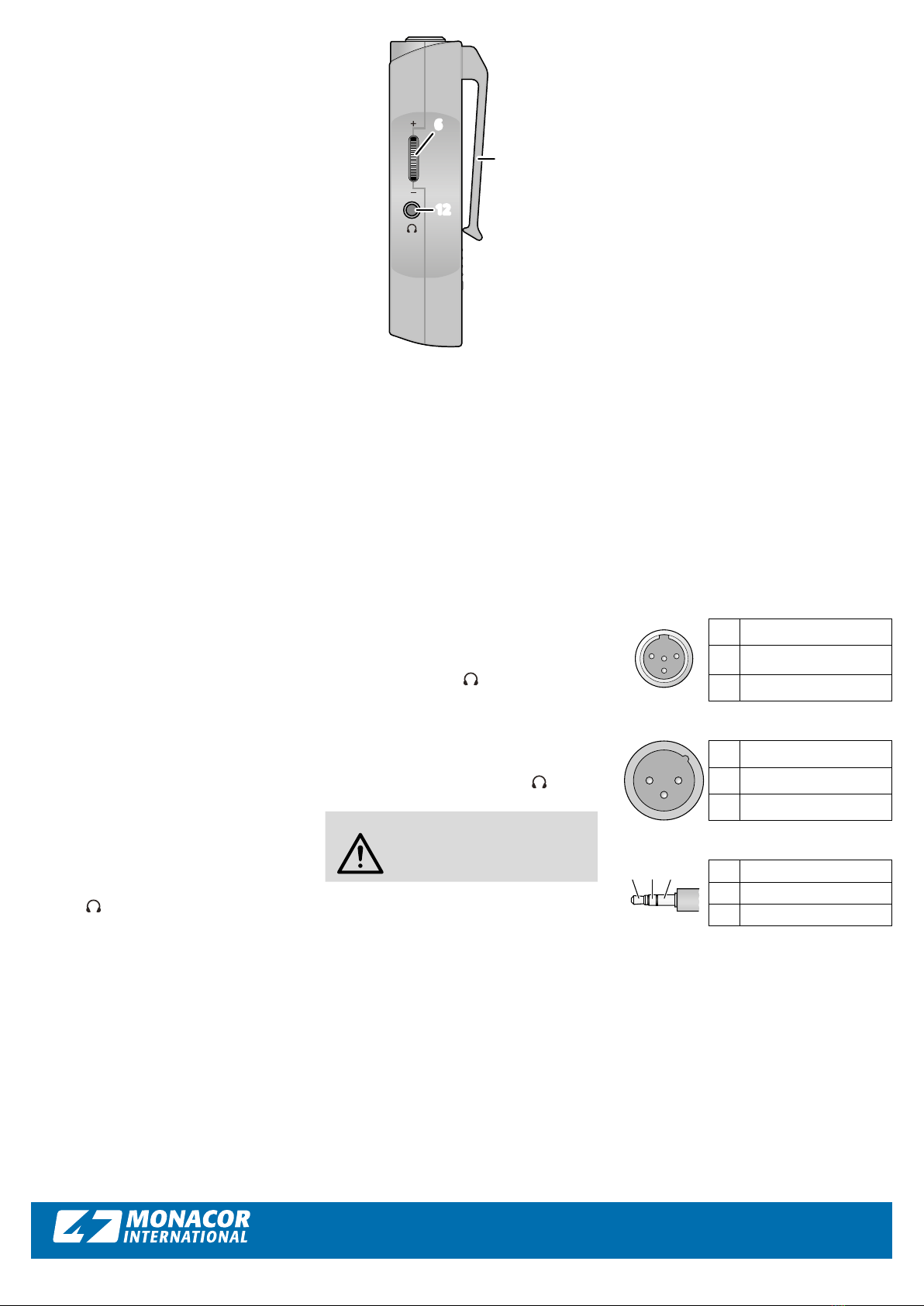
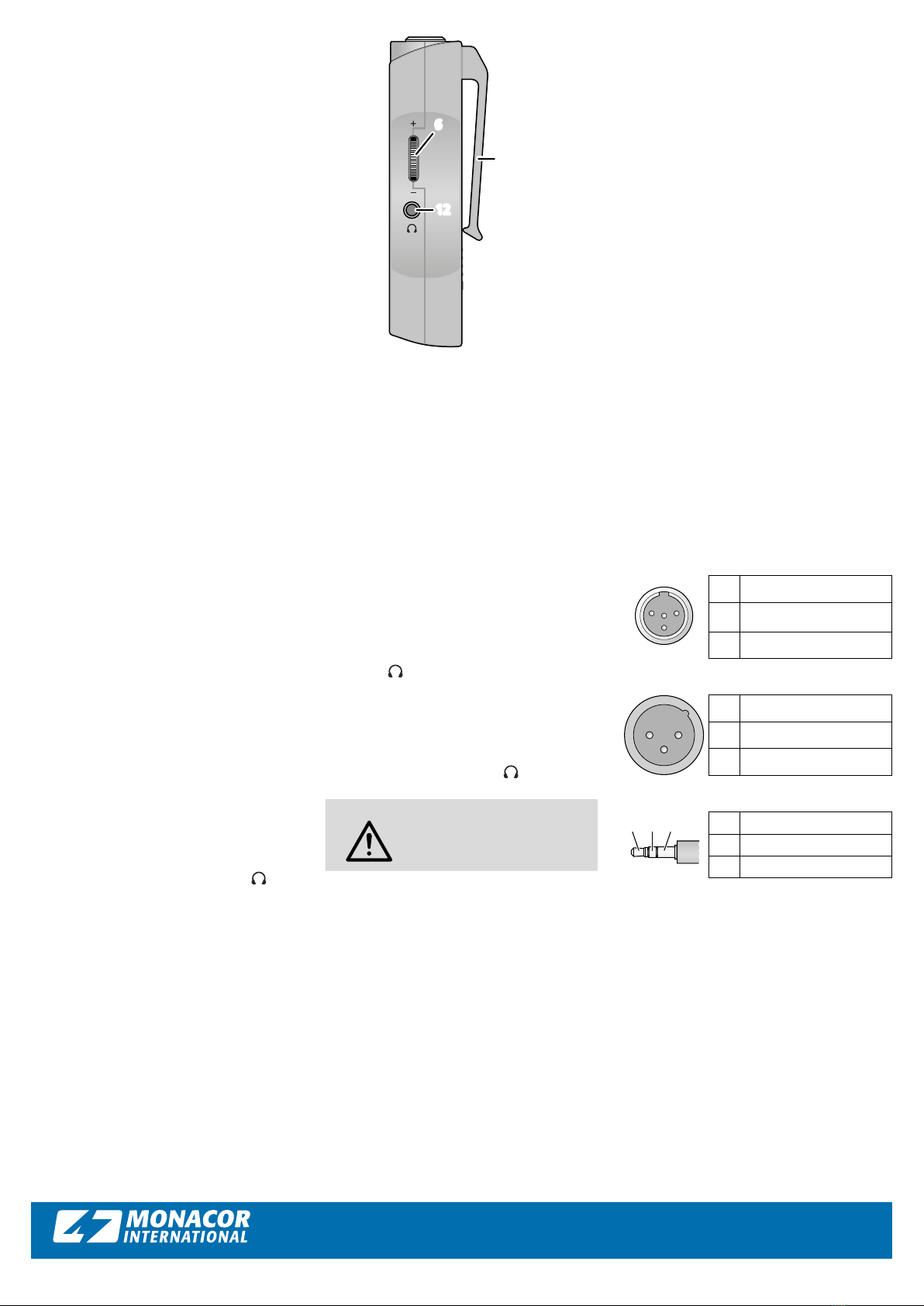
Le mixeur peut être fixé sur un vêtement
grâce à sa pince de ceinture (10) sur la face
arrière.
2 Conseils importants
Le produit répond à toutes les directives
nécessaires de l’Union européenne et porte
donc le symbole .
• Le produit n’est conçu que pour une utilisa-
tion en intérieur. Protégez-les des éclabous-
sures, de tout type de projections d’eau et
d’une humidité d’air élevée. La plage de tem-
pérature ambiante admissible est de 0–40°C.
• Pour le nettoyage, utilisez uniquement un
chiffon sec et doux, en aucun cas de pro-
duits chimiques ou d’eau.
• Nous déclinons toute responsabilité en cas
de dommages corporels ou matériels résul-
tants si le produit n’est pas correctement uti-
lisé ou s’il n’est pas réparé par une personne
habilitée ; de même, la garantie deviendrait
caduque.
Lorsque le produit est définitivement
retiré du service, éliminez-le conformé-
ment aux directives locales.
Ne jetez pas les batteries dans la poubelle
domestique. Déposez-les dans un container
spécifique pour les éliminer conformément aux
directives locales.
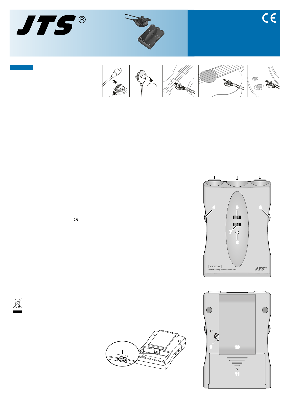
3 Fonctionnement
3.1 Fixation des microphones
Comme indiqué sur le schéma 1, fixez le cor-
don du micro miniature sur la face supérieure
du socle de fixation, près de la capsule micro.
Fixez la partie inférieure du socle dans lequel se
CX-500DUSET
Référence numérique 23.6710
Set de microphones
pour instruments
FRANÇAIS
➀
trouve le micro de contact, sur l’instrument (par
example violon, guitare, piano) à l’aide d’un
des coussins adhésifs livrés. Si besoin, faites
des tests pour trouver la meilleure position de
montage pour un son optimal. Une orientation
précise du micro miniature n’est pas nécessaire
car il est omnidirectionnel. Si besoin, placez la
bonnette de protection en mousse sur la cap-
sule micro du micro miniature.
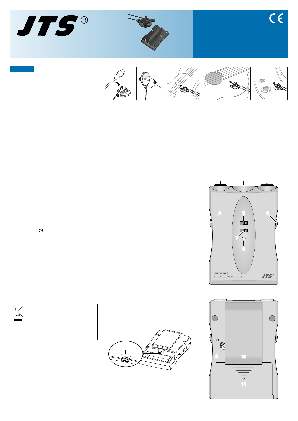
3.2 Insertion/remplacement de la batterie
Pour insérer ou remplacer la batterie, poussez
le couvercle (11) du compartiment batterie
vers le bas. Une fois la batterie existante reti-
rée, reliez les connecteurs de la batterie neuve
aux contacts correspondants. Remettez le cou-
vercle pour fermer le compartiment.
3.3 Sélection de l’alimentation
L’interrupteur PHANTOM/BATTERY (5) sert
pour sélectionner le type d’alimentation. Il
peut également être utilisé comme interrup-
teur marche/arrêt (☞chapitre 4.1).
BATTERY : Le mixeur et les microphones sont
alimentés via une batterie insérée.
PHANTOM : L’alimentation se fait via une ali-
mentation fantôme (12–48V)
disponible à l’entrée micro de
nombreuses tables de mixage et
préamplificateurs.
Important : Pour éviter les bruits forts de commu-
tation pendant le fonctionnement, n’activez cet
interrupteur que si le son de l’entrée est coupé ou si
le volume est baissé sur l’appareil relié (par exemple
table de mixage ou amplificateur).
3.4 Sélection du niveau de sortie
On peut adapter le niveau de sortie du mixeur
à la sensibilité d’entrée de l’appareil suivant.
Pour ce faire, ouvrez le compartiment batterie
(11) et si besoin, retirez la batterie pour que
l’interrupteur (13) soit accessible.
13
➁
MIC. : pour brancher à une entrée micro
LINE: pour brancher à une entrée niveau
ligne (p.ex. «LINE IN» ou «AUX IN»)
Si la sensibilité de l’entrée n’est pas connue,
mettez tout d’abord l’interrupteur sur la posi-
tion LINE ; si la restitution audio est trop basse,
il est possible de commuter ultérieurement sur
MIC.
Important : Pour éviter les bruits forts de commu-
tation pendant le fonctionnement, n’activez cet
interrupteur que si le son de l’entrée est coupé ou si
le volume est baissé sur l’appareil relié (p.ex. table
de mixage ou amplificateur).
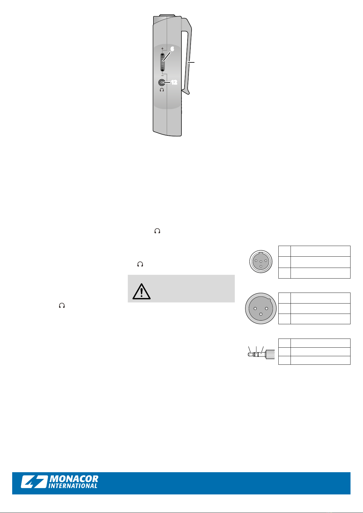
IN L
PHANTOM BATTERY
ON MUTE
IN R
54 6
8
7
➂
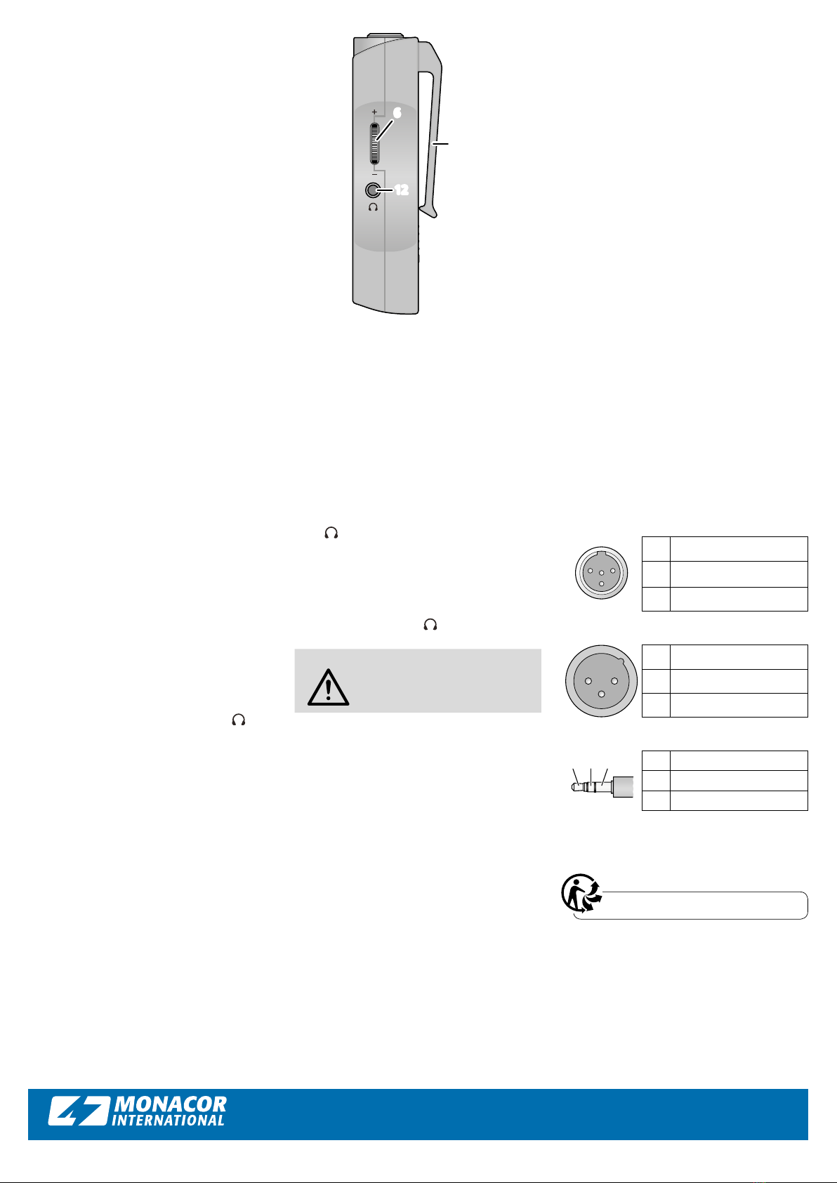
VOL
10
9
11
➃