JUKI DLN-6390 Quick start guide

R
ENGINEER’S MANUAL
40011375
No.E356-00
High-speed, 1-needle, Cylinder-bed, Needle-feed, Lockstitch
Machine with Large Hook
DLN-6390
High-speed, 1-needle, Cylinder-bed, Needle-feed, Lockstitch
Machine with Automatic Thread Trimmer and Large Hook
DLN-6390-7

PREFACE
This Engineer’s Manual is written for the technical personnel who are responsible for the service and maintenance of
the machine.
The Instruction Manual for these machines intended for the maintenance personnel and operators at an apparel
factory contains operating instructions in detail. And this manual describes “Standard Adjustment”, “Adjustment
Procedures”, “Results of Improper Adjustment”, and other important information which are not covered by the Instruction
Manual.
It is advisable to use the relevant Instruction Manual and Parts List together with this Engineer’s Manual when carrying
out the maintenance of these machines.
In addition, for the motor for the sewing machine with thread trimmer, refer to the separate Instruction Manual or
Engineer’s Manual for the motor. And for the control panel, refer to the Instruction Manual for the control panel.
This manual gives the “Standard Adjustment” on the former page under which the most basic adjustment value is
described, and on the latter page “Results of Improper Adjustment” under which stitching errors and troubles arising
from mechanical failures are described together with the “Adjustment Procedures”.

CONTENTS
1. OUTLINE ........................................................................................................... 1
(1) Features ............................................................................................................................ 1
(2) Specifications .................................................................................................................... 1
(3)Application .......................................................................................................................... 1
2. OPERATION...................................................................................................... 2
(1) Names of each components.............................................................................................. 2
(2) Matters to be checked before operation and trial run ........................................................ 2
3. THREAD TRIMMING ......................................................................................... 3
(1) Principle of thread trimming............................................................................................... 3
(2) Sequence of thread trimming ............................................................................................ 3
4. STANDARD ADJUSTMENT ............................................................................. 4
(1) Adjusting the height of the needle bar ............................................................................... 4
(2) Hook timing........................................................................................................................ 4
(3) Adjusting the needle stop position..................................................................................... 6
(4) Checking and adjusting the receding position of the moving knife.................................... 8
(5) Removing/installing the knife unit .................................................................................... 10
(6) Checking and adjusting the thread trimmer cam timing .................................................. 12
(7) Installing the counter knife............................................................................................... 14
(8) Replacing the moving knife ............................................................................................. 14
(9) Disk rising amount of the thread tension controller (asm.) .............................................. 16
(10) Adjusting the clutch plate and the thread trimmer magnet ............................................ 16
(11) Adjusting the driving arm stopper .................................................................................. 18
(12) Replacing the synchronizer and adjusting the position of the handwheel ..................... 18
(13) Adjusting and assembling the needle feed adjustment mechanism.............................. 20
(14) Adjusting and assembling the needle feed mechanism ................................................ 22
(15) Assembling the reduction gear ...................................................................................... 24
(16) Adjusting the belt tension .............................................................................................. 26
(17) Removing/installing the oil reservoir.............................................................................. 26
(18) Adjusting the position of the hemming binder cylinder .................................................. 28
(19) Installing the presser .....................................................................................................28
(20) Bobbin case................................................................................................................... 30
(21) Adjusting sewing............................................................................................................ 32
5. SETTING OF SC-380 ......................................................................................34
6. MAINTENANCE............................................................................................... 36
(1) How to sharpen the knife................................................................................................. 36

7. TROUBLES AND CORRECTIVE MEASURES............................................... 37
(1) With regard to mechanical components .......................................................................... 37
(2) With regard to sewing...................................................................................................... 41
8. DRAWING OF TABLE.....................................................................................47

−1−
DLN-6390 DLN-6390-7
Knee lifter (by manual) : 12.5 mm Auto-lifter : 12.5 mm
By manual Air cylinder drive
400W or higher power clutch motor
can be used.
1. OUTLINE
(1) Features
1) The machine incorporates the mechanical horizontal thread trimming system that has achieved with JUKI lockstitch
machines and the thread trimming performance has improved as com pared with the conventional models.
2) The forced lubrication system of JUKI lockstitch machine system is incorporated in the face plate section and the hook,
and the reliability is improved by stable lubrication. In addition, the forced lubrication mechanism by the plunger pump
is equipped to the face plate section and the hook section, and oil leakage is prevented at the time of sewing.
3) In order to improve the sewing environment and to reduce the operator’s burden, vibration and noise at the time of
sewing are reduced as compared with the conventional machines.
4) Scales are added to the respective adjustment sections of thread tension knob, presser spring regulator, etc., and
simplification of adjustment work is considered as well.
5) For the roller feed mechanism, the structure of the conventional machine which is highly appreciated in the market has
been succeeded, and the smooth feed at step section has been realized.
6) Common use of presser foot, roller, hemming binder, pitch changeover gear, etc. with the conventional machines is
attempted, and the exchangeability of gauges is secured.
7) A thread trimming blow device is equipped as standard and thread trimming failure due to the thread trimming section
clogged with dust is prevented.
8) The stepless dial adjustment system is incorporated for the adjustment of needle feed amounts, and the needle feed
amounts can be adjusted without using tools.
9) Workability in the process of sewing thick denim or multi-layered sections is improved since the needle bar stroke is 35
mm and max. 14 mm of the lift of the roller is secured.
(2) Specifications
No.
1
2
3
4
5
6
7
8
9
10
11
12
13
14
(3) Application
1) The machine comes standard with the binder of rolled hemming width of 1/2" for jeans at the time of
delivery. However, the machine can be used for the broad range of materials such as chinos, corduroy,
etc. by replacing optional binder (1"), presser foot (3/8", 1") and upper/lower rollers.
2) An edge guide is supplied with the machine as standard accessory and it is possible to sew lining.
Application
Max. sewing speed
Stitch pitch
Needle
Needle bar stroke
Thread take-up stroke
Hook
Lift of presser foot
(Throat plate to bottom surface
of presser foot)
Feed method
Hemmer opener type
Lubrication oil
Stitch length adjusting method
Needle clamp method
Motor
Model
Item Bottom hemming, waist band attaching (lockstitch type), hemming
(lockstitch type)
When stitch length is less than 3.6 mm : 5,000 rpm
When stitch length is not less than 3.6 mm : 4,500 rpm
2.1 mm, 2.3 mm, 2.5 mm, 2.8 mm, 3.2 mm (standard), 3.6 mm, 4.2 mm
SCHMETZ UY180GVS Standard Nm140 (shank diameter ø1.84)
Range of use : Nm75 to Nm150 (equivalent to #11 to #22.5)
35mm
123mm
Exclusive automatic lubricating full-rotary 1.7 fold hook (standard hook
can be used.) Presser lifting lever : 4.5 mm
Upper/lower roller continuous feed method
New Defrix Oil No. 1 (equivalent to ISO VG7)
Gear replacement method
Nut clamp method
SC-380

−2−
2. OPERATION
(1) Names of each components
1Needle feed dial
2Hemming binder
3Hemming binder cylinder
4Oil reservoir
5Oil gauge
6Gear cover
7Wiper
8Thread tension No. 1
9Thread tension controller (asm.)
(2) Matters to be checked before operation and trial run
(Matters to be checked)
1) Check whether wiring is securely performed to the control box.
2) Check whether the oil reservoir is filled with oil.
3) First, run the sewing machine at low speed and check whether there is any noise.
(Trial run)
1. Pedal operation
The pedal is operated in the following 5 steps.
1The machine runs at low sewing speed when you lightly depress the front part of the pedal.
2The machine runs at high sewing speed when you further depress the front part of the pedal.
3The machine stops when you return the pedal to stop (neutral) position.
4The presser foot goes up when you lightly depress the back part of the pedal.
5Presser foot comes down athread trimmer is actuated aneedle stops at UP position awiper is
actuated apresser foot goes up when you fully depress the back part of the pedal.
Low speed
Stop (neutral)
High speed
Presser foot lift
Thread trimming
High speed
Low speed
Presser foot lift
Thread trimming
Stop
12345
67
9
8

−3−
1. Blade point of the hook scoops needle thread.
3. THREAD TRIMMING
(1) Principle of thread trimming
(2) Sequence of thread trimming
3. Moving knife handles needle thread
(travels backward).
5. Moving knife catches needle /bobbin threads
(travels forward).
2. Needle thread crosses over the hook.
4. Needle thread is caught with the thread draw-out plate
(moving knife travels backward up to the end).
6. Thread is trimmed.
Depress front
part of pedal.
Low speed to
high speed
Pedal neutral
(Stop position)
DOWNstop
ThreadtrimmingMg
ON, machine runs
Moving knife
starts.
Moving knife handles
thread (Moving knife
travels backward.)
Needle thread is caught with
thread draw-out plate. (Moving
knifetravelsbackward up toend.)
Thread trimming
hreadtrimming
Mg OFF
Tension release
Mg OFF
DOWN detection
signal detection
Depress back
part of pedal.
Engagement of
cam and roller
Thread crosses
over hook.
Tension release
Mg ON
Movingknifecatchesneedle/
bobbinthreads. (Movingknife
travels forward.)
UP detection
signal detection
Disengagement
of cam and roller
UP stop

−4−
4. STANDARD ADJUSTMENT
(1) Adjusting the height of the needle bar
Standard Adjustment
1
2
3
4
A
2
Standard Adjustment
(2) Hook timing
1
2
3
56
7
8
9
ab
c
B
D
E
4
5
2
b
0 to 0.06 mm
!0
0.8mm
!2
!1
!0
A
B
B
A

−5−
Adjustment Procedures Results of Improper Adjustment
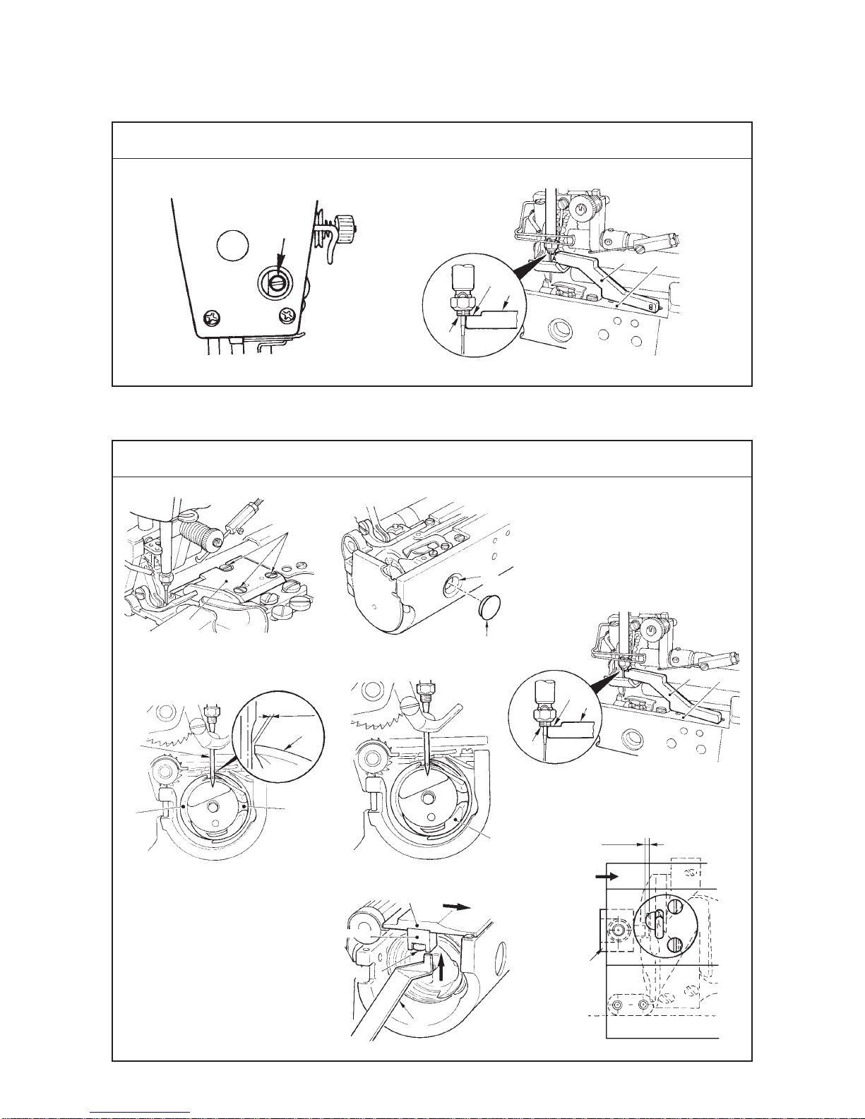
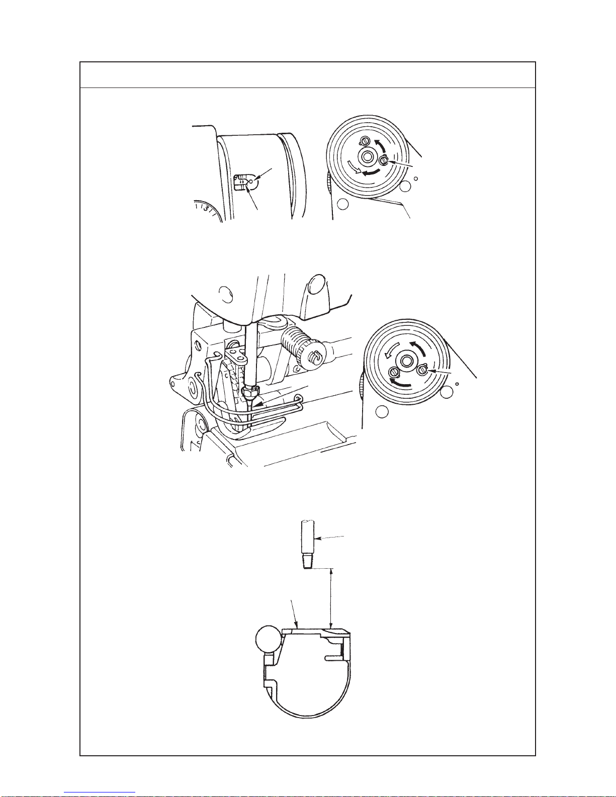
1) Turn the handwheel to bring the needle bar to the lowest position
of its stroke, and loosen setscrew 1in the needle bar bracket.
2) Set needle bar height gauge 2supplied with the machine as
accessories to installing plane 3of the throat plate as shown
in the figure, and make bottom end 4of the needle bar come
in contact with plane A(engraved A marking) of needle bar
height gauge 2. Then tighten setscrew 1in the needle bar
bracket.
1) Remove setscrews 1and remove throat plate 2.
2) Remove cap 3, and put a screwdriver from hole 4to loosen
three setscrews in the hook. Turn the handwheel in the direction
where needle bar goes up, set needle bar height gauge 5to
installing plane 6of the throat plate as shown in the figure,
and adjust the position so that plane B(engraved B marking)
of needle bar height gauge 5enters bottom end 7of the
needle bar.
3) Adjust blade point 8of hook ato the center of needle 9.
Then adjust so that the clearance provided between the needle
and the hook is 0 to 0.06 mm (standard), and securely tighten
three setscrews in the hook. (Tightening torque : 2 to 4N.m)
* Adjust inner hook bat the position as shown in the figure.
4) Install cap 3and throat plate 2, and securely tighten setscrews
1. (Tightening torque : 1.5 to 3N.m)
* Adjust the convex of bobbin case holder !0 to the concave of
inner hook bwhen installing the throat plate.
* Tighten setscrews 1and install throat plate 2while pushing
throat plate 2by hand in the direction of arrow mark cwhen
installing throat plate 2.
5) Adjust clearance Dprovided between the convex of the bobbin
case holder and the concave of the inner hook with gauge !2
supplied with the sewing machine as accessories. (Standard :
0.8 mm)
* Put gauge !2 supplied as accessories in clearance Dand
tighten setscrew !1while lightly pushing bobbin case holder !0
in the direction E. (Tightening torque : 1.5 to 2.5N.m)
* Check that gauge !2 can go in clearance Dand come out
from it with light resistance.
™Thread breakage will be caused
even when the height of the
needle is excessively high or
low.
™When hook timing is excessively
retarded (return amount is large)
Contact of the blade point of the
hook with the belly of needle is
increased resulting in stitch
skipping or thread breakage at
the time of sewing of overlapped
section.
™When hook timing is excessively
advanced (return amount is
small)
Thread loop becomes smaller
resulting in stitch skipping or
thread breakage at the time of
sewing of overlapped section.

−6−
Standard Adjustment
(3) Adjusting the needle stop position
1
2
3
4
5
A
B
C
D
E
F
44.1mm

−7−
Adjustment Procedures Results of Improper Adjustment
1. Stop position after thread trimming
1) The standard needle stop position is the position where pointer
Aon the machine arm aligns with white marker dot Bon the
handwheel. (Main shaft timing : 57.5˚)
2) Stop the needle at UP position, and loosen screw 1to perform
adjustment within the range of the slot.
™To advance UP stop position adirection of C
™To retard UP stop position adirection of D
2. DOWN stop position
1) The needle DOWN stop position when the pedal is returned to
the neutral position after the front part of the pedal is depressed
can be adjusted within the range of the slot by loosening screw
2after making needle 3stop at DOWN stop position.
™To advance DOWN stop position adirection of E
™To retard DOWN stop position adirection of F
(Caution) 1. Do not operate the machine with screws 1
and 2loosened. In addition, just loosen
the screws, and do not remove them.
2. When the UP stop position is excessively
advanced, the sewing machine stops before
completion of the thread trimming motion,
and there is a possibility of the occurrence
that thread is not trimmed. In addition, when
it is excessively retarded, there is a
possibility that the needle tip projects the
bottom surface of the presser foot or the
sewing machine overruns at the time of UP
stop.
Use the sewing machine at the position
where pointer Aon the machine arm aligns
with white marker dot Bon the handwheel.
3. Do not move the pointer on the arm since it
has been factory-adjusted according to the
base of the height of the needle bar at the
time of delivery. In case it has been moved,
adjust the needle feed dial to “P = 0”, and
precisely adjust the distance from the top
end of needle bar 4to the top surface of
throat plate 5to 44.1 mm when the needle
comes down. In this state, make white
marker dot Bon the handwheel align with
pointer Aon the machine arm.
4. When the UP stop position is adjusted,
check whether the needle comes in contact
with the wiper.

−8−
Standard Adjustment
(4) Checking and adjusting the receding position of the moving knife
™ Wiring diagram of pneumatic and electric components
Gray
Black
DLN-6390-7 main unit
Black
DLN-6390-7 main unit
Normal wiring
Moving knife receding amount at the time of checking cam timing
Gray
Correct position where
moving knife has fully
receded
Moving knife waiting
position
6
2
3
4
51
7
A
3
8
!4
B
C
N
D
E
FG
9
!0
!1
E
E
I
I
I
2
Y
Z
Y
Z
Y
Z
Y
Z
S. M.
DETECTOR
F. L.OPTION B
S. M.
DETECTOR
F. L.OPTION B

−9−
Adjustment Procedures Results of Improper Adjustment
1) Make sure that the power to the sewing machine is turned OFF.
2) Removesetscrews1,setscrews2andsetscrews3.Then remove
hemming binder 4, auxiliary throat plate 5and throat plate 6.
3) Replace the connectors.
™Disconnect connector Zfrom SC-380.
™Disconnectconnector YandconnectconnectorYto the detector
of SC-380 to which connector Zwas connected. (Refer to the
wiring diagram of pneumatic and electrical components.)
4) Turn ON the power to the sewing machine.
5) Turn handwheel 7by hand in the normal direction of rotation Aof
the sewing machine.
(Normal direction of rotation Aof the sewing machine is the
counterclockwise direction as observed from the handwheel side.)
6) When the needle bar goes up and the top end of needle comes
higherthan themoving knife,depressthe backpart ofpedal 8in the
direction B.
(Caution) Never depress the front part of pedal 8in the direction C.
(Bydepressing the back partofthe pedal, thethread trimmermagnet
is turned ON and the roller enters the thread trimmer cam in the
sewing machine.)
7) Then turn handwheel7by handin the normaldirection of rotationof
the sewing machine.
8) Moving knife lever 9turns counterclockwise in the direction Dand
moving knife !0 starts receding in the direction E.
9) When moving knife !0 has fully receded, the position where convex
Fof moving knife !0 aligns with end Gof the thread draw-out plate
is the correct position of moving knife receding position.
(Caution) The power switch has been turned ON during the
operationof steps 4) through9).Never depress the front
part of pedal 8in the direction C.
10) If the receding amount is not proper, be sure to turn OFF the
power switch of the sewing machine, loosen moving knife lever
tightening screw !1, and tighten moving knife lever tightening
screw !1 (tightening torque : 3 to 4 N.m) so that convex Fof
moving knife !0 aligns with end Gof the thread draw-out plate to
adjust again the moving knife to the correct receding position.
* The work of checking and adjusting the fully receding position of the
moving knife is completed in steps 1) through 10). Be sure to return
the connector which has been replaced in step 3) to the home place,
and return the components which have been removed in steps 1)
and 2) to the home places as well. Then securely tighten the
setscrews.
* When installing the throat plate, push it in the direction of arrow mark
Nand tighten setscrews 3in the state that stopper !4 comes in
contact with the frame.
* When adjusting the receding position of the moving knife, adjust the
position in the state that the backlash is drawn in the direction of I.
™Thread trimming failure will occur
when the receding position of
the moving knife is larger or
smaller than the correct position.

−10 −
Standard Adjustment
Moving play of knife unit
(5) Removing/installing the knife unit
AB
12 3

−11 −
Adjustment Procedures Results of Improper Adjustment
Do not remove it unless it is necessary.
And, along with the change of knife assembly position, the tail
end of moving knife also moves to backward, when re-adjustment
of positioning is necessary to make both the units work in
conformity.
Refer to "(4) Checking and adjusting the receding position of the
moving knife."
[Removing]
1) Remove the throat plate.
2) Hold up moving knife connecting link 1and remove moving
knife connecting link 1from pin 2of the moving knife.
3) Remove two setscrews 3in the knife unit and remove the
knife unit.
[Installing]
Installing can be performed by reversing the above removing order.
However, when installing the knife unit, adjust the position of the
knife unit by adjusting the part of play of the screw hole by the
procedure below.
1) Move the moving knife connecting link knife unit to the direction
of face plate section (direction A bin the figure) as much as
the play at the installing hole and fix the unit.
2) When needle thread trimming failure occurs at the fixed position
of moving knife connecting link 1at the time of thread trimming,
move the knife unit to the direction of handwheel (direction B
ain the figure) as much as the play and re-adjust it.

−12 −
Standard Adjustment
(6) Checking and adjusting the thread trimmer cam timing
No clearance
provided
A
8
B
1. Checking the thread trimmer cam timing
2. Adjusting the thread trimmer cam timing
Turn cam in
this direction.
7
J
!2
!3
KL
M
9
!0
I
H
I
I
1
2
3
5
6
2
46.8mm
47.1mm
47.4mm
Correct position where
moving knife has fully
receded
Moving knife waiting
position
234
!1
!4

−13 −
Adjustment Procedures Results of Improper Adjustment
1. Checking the thread trimmer cam timing
The work up to steps 1) through 8) is the same as that of (4) Checking
and adjusting the receding position of the moving knife.
Execute the work up to steps 1) through 8).
9) Then turn handwheel 7in the normal direction of rotation of the sewing
machine Awhile depressing the back part of pedal 8in the direction B.
(Moving knife lever 9turns clockwise in the direction Hafter the moving
knife has fully receded, and moving knife !0 starts moving in the direction
Ito return to the waiting position.
10) When turning handwheel 7in the reverse direction of rotation of the
sewing machine Jafter the moving knife has returned to the waiting
position, the handwheel cannot turn at a certain angle.
(Caution) Be sure to turn OFF the power switch to the sewing machine
after completion of the work of steps 4) through 10).
11) When the height of the needle bar from the top surface of the throat
plate is 46.8 to 47.4 mm, the thread trimmer cam timing is normal.
12) It is easy to check the height when the gauge supplied as accessories
is used.
When section Kof the gauge enters between the throat plate and the
bottom end of the needle bar and section Ldoes not enter, the height
of the needle bar is within the range of 46.8 to 47.4 mm and the thread
trimmer cam timing is normal.
13) When entering the gauge in the bottom end of the needle bar, loosen
setscrew !2 and remove presser foot !3. Return presser foot !3 to the
home position after the completion of the work and securely tighten
setscrew !2. (Tightening torque : 1.5 to 2N.m)
14) When the height of the needle bar from the top surface of the throat
plate is not 46.8 to 47.4 mm, the thread trimmer cam timing is not proper.
Adjust the thread trimmer cam timing according to 2. Adjusting the thread
trimmer cam timing below
2. Adjusting the thread trimmer cam timing
1) Loosen setscrews 1in the thread trimmer cam in the order of screw
No. 1 to screw No. 2.
2) Press down roller arm 2to make thread trimmer cam 3and roller 4
engage with each other.
* Workability is improved when medium-sized screwdriver 5supplied
as accessories or the like is inserted between roller arm 2and driving
arm stopper 6.
(Caution) Make the state that roller arm 2is fully pressed down so
that the clearance is not provided between roller arm 2
and knife driving arm !1.
3) Turn the handwheel to the right direction,then stop it where the distance
between of bottom end of needle bar and surface of the throat plate
comes to meet the mark M.
4) Turn thread trimmer cam 3only by fingertip in the reverse direction of
rotation of the hook driving shaft without turning the hook driving shaft,
lightly press thread trimmer cam 3to roller 4at the position where
thread trimmer cam 3does not turn, and tighten screw No. 2 of thread
trimmer cam 3.
* When cam collar !4 is not moved, press thread trimmer cam 3to cam
collar !4 and tighten thread trimmer cam 3.
5) Draw out screwdriver 5inserted between roller arm 2and driving arm
stopper 6, and tighten screw No. 1 of thread trimmer cam 3.
6) After adjusting the cam timing, check the timing described in the previous
item. (Height of the needle bar is within the range of gauges K, Mand
L.)
™Thread trimmer cam timing is set
in accordance with the standard
value (return amount : 1.8 mm)
of the hook timing.
When the hook timing is
excessively changed from the
standard value, even when the
thread trimmer cam timing is
adjusted to the standard value
(46.8 to 47.4 mm), thread
trimming failure occurs. So, be
careful.

−14 −
Standard Adjustment
(7) Installing the counter knife
(8) Replacing the moving knife
To be in
the center
Installing
plane
Center of
needle
Standard Adjustment
BA
0.5mm
4.5mm
1
2
1
2
1
2

−15 −
Adjustment Procedures Results of Improper Adjustment
1) The correct installing position of counter knife 1is that the
distance from the center of the needle to the blade tip of counter
knife 1is 4.5 mm and that the eyelet of moving knife 2is
positioned so as to pass the center of the blade tip of counter
knife 1.
2) It is the aim that the blade tip of counter knife 1is positioned
at 0.5 mm above from the installing plane.
3) When counter knife 1is moved in the direction A as shown in
the figure, the length of remaining needle thread on the needle
after thread trimming will be longer and when it is moved in the
direction B, the length will be reversely shorter.
* When adjusting or replacing counter knife 1, be sure to check
the sharpness and adjust the installing position of counter knife
1.
1) Replacement of moving knife 1can be performed with ease
by removing moving knife hinge screw 2only. (Hexagon width
: 6 mm)
2) When moving knife 1is replaced, check that moving knife 1
smoothly moves after tightening moving knife hinge screw 2.
™When the position of counter
knife 1is excessively moved to
side B, thread trimming failure
(slip-off of needle thread at the
start of sewing or the like) may
occur.
Adjustment Procedures Results of Improper Adjustment

−16 −
Standard Adjustment
(9) Disk rising amount of the thread tension controller (asm.)
(10) Adjusting the clutch plate and the thread trimmer magnet
Section A
1
2
A
12
3
4
3
4
5
6
4
3
Standard Adjustment
7
Other manuals for DLN-6390
3
This manual suits for next models
1
Table of contents
Other JUKI Sewing Machine manuals

JUKI
JUKI MEB-3200C User manual

JUKI
JUKI MO-613 User manual

JUKI
JUKI LZ-2290A-SS-7 Quick start guide

JUKI
JUKI HZL-E80 User manual

JUKI
JUKI TL Series User manual

JUKI
JUKI LZH-1290 User manual

JUKI
JUKI CP-180 User manual

JUKI
JUKI SC-921 User manual

JUKI
JUKI LZ-271 User manual

JUKI
JUKI APW-895/IP-420 User manual