−4 −
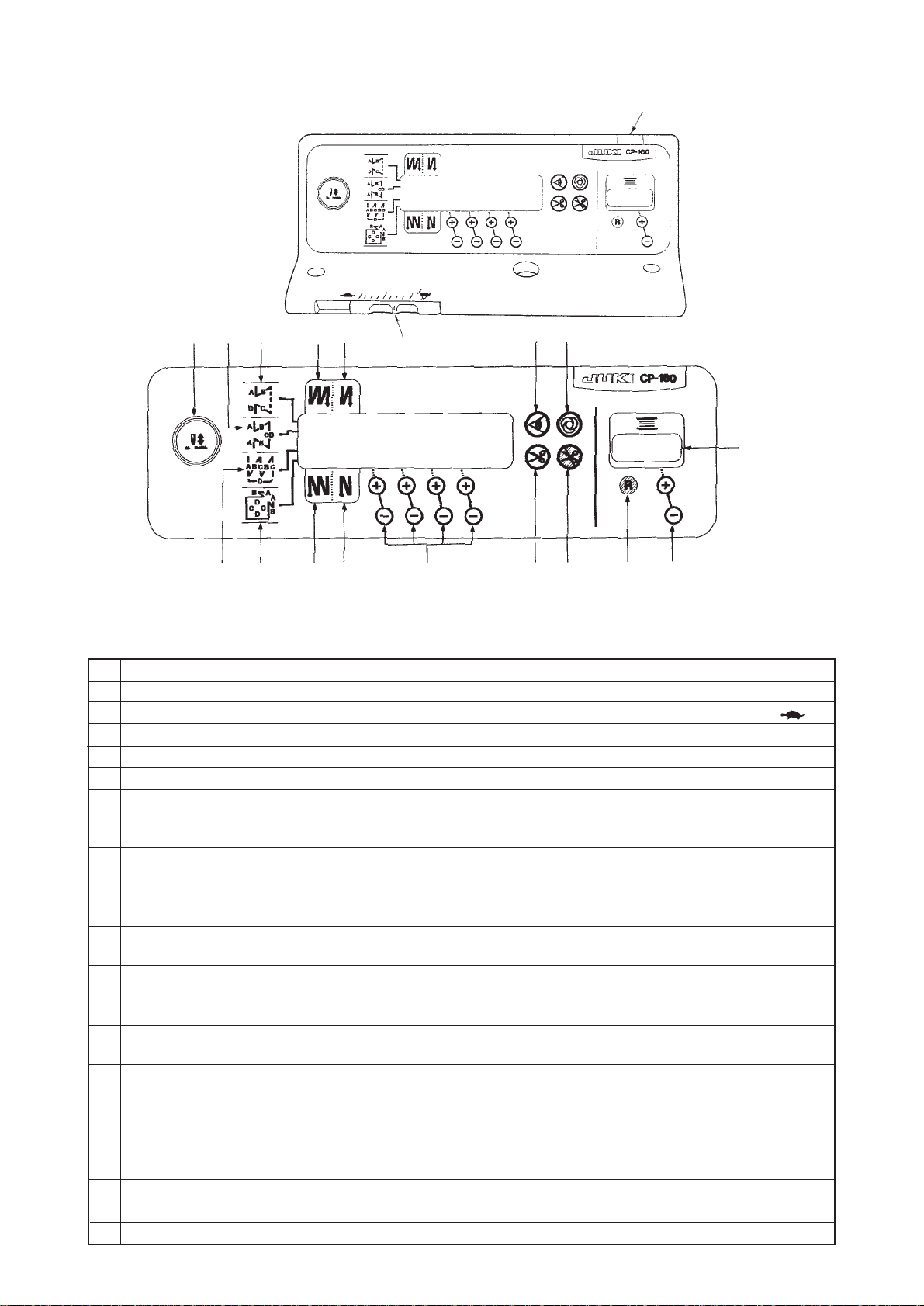
(2) Explanation of control panel CP-160
1) Reverse stitching pattern When the sewing machine performs the free stitching operation, the
machine performs the reverse stitching operation at the start and end of
sewing.
The reverse stitching operation can set the ON and OFF settings.
Furthermore, single and double reverse stitching patterns can be
selected.
Setting of number of stitches or other settings can be performed by
operating the control panel.
A, B, C and D = 0 to 19 stitches
2) Overlapped stitching pattern
The sewing machine repeats the normal stitching and reverse stitching
by the predetermined time, and performs the line bartacking. Then, the
machine makes the thread trimmer actuate and stop to complete the
overlapped stitching procedure.
Change of the number of stitches or the number of times of repetition
can be performed by operating the control panel.
A, B and C = 0 to 19 stitches
D = 0 to 9 times
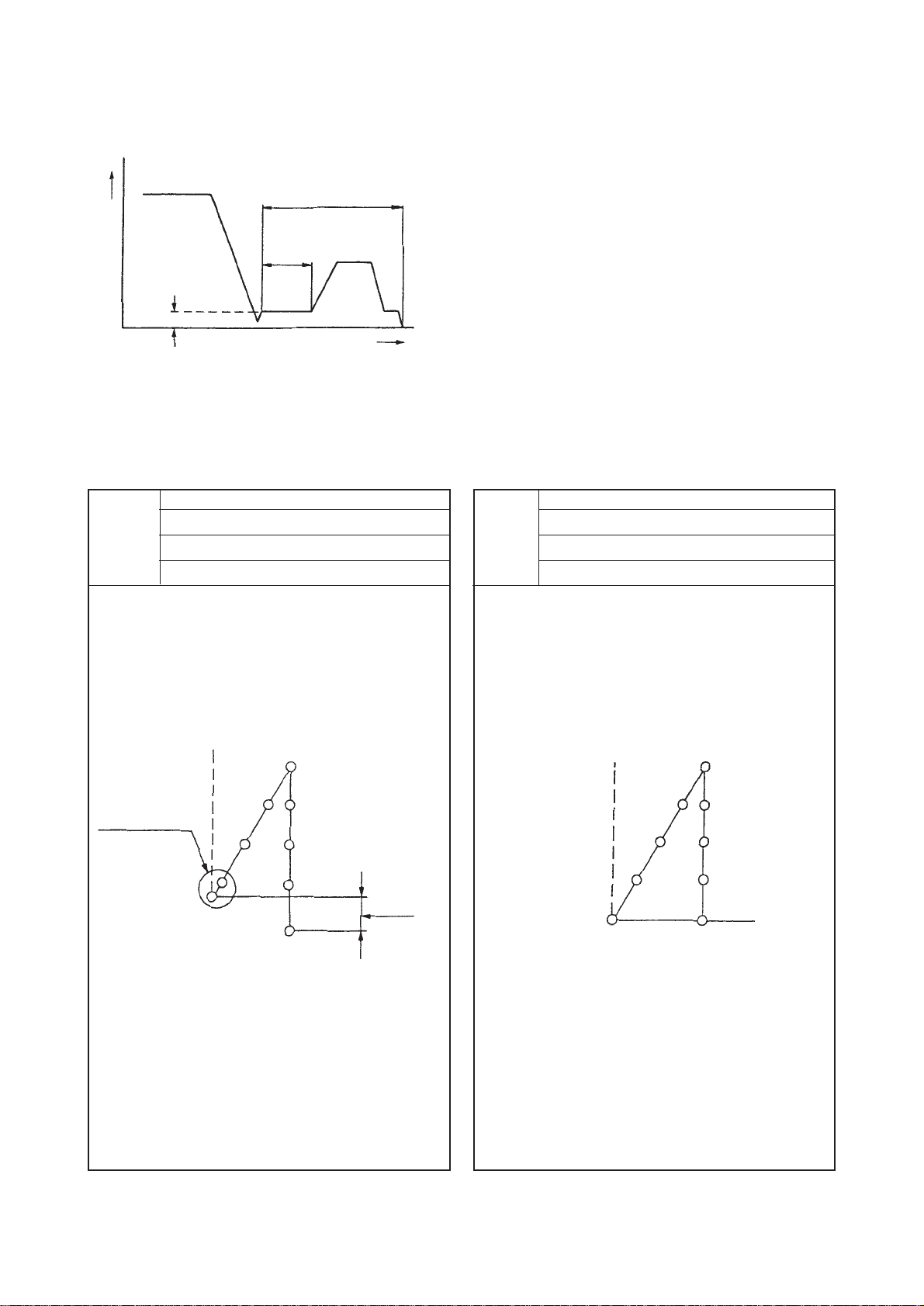
3) Constant-dimension stitching pattern
The free stitching process in the reverse stitching pattern becomes the
set value of the number of stitches. The sewing machine will automatically
stop (automatically perform thread trimming if the automatic thread
trimming is selected.) after the machine finishes the predetermined
number of stitches in the process of CD.
If the automatic thread trimming is not selected, operate the touch-back
switch after the machine has automatically stopped. Then, the machine
runs at a low speed (stitch compensation operation). Also, if the pedal is
returned to its neutral position and depressed its front part again, the
sewing can be continued regardless of the setting of number of stitches.
Setting of number of stitches or selection of automatic thread trimming
can be performed by operating the control panel.
A and B = 0 to 19 stitches CD = 0 to 500 stitches
4) Rectangular stitching pattern
There are 4 operation steps in the process of constant-dimension stitching
pattern. At each operation step the sewing machine automatically stops
after sewing the predetermined number of stitches. At this time, if the
touch-back switch is operated, the sewing machine runs at a low speed
(stitch compensation operation). Also, in case of the last operation step,
if the pedal is returned to its neutral position and depressed its front part
again, the sewing can be continued regardless of the setting of number
of stitches. However, if the automatic thread trimming is set, the machine
will perform thread trimming. Setting of number of stitches or selection
of automatic thread trimming can be performed by operating the control
panel.
A and B = 0 to 19 stitches C and D = 0 to 99 stitches