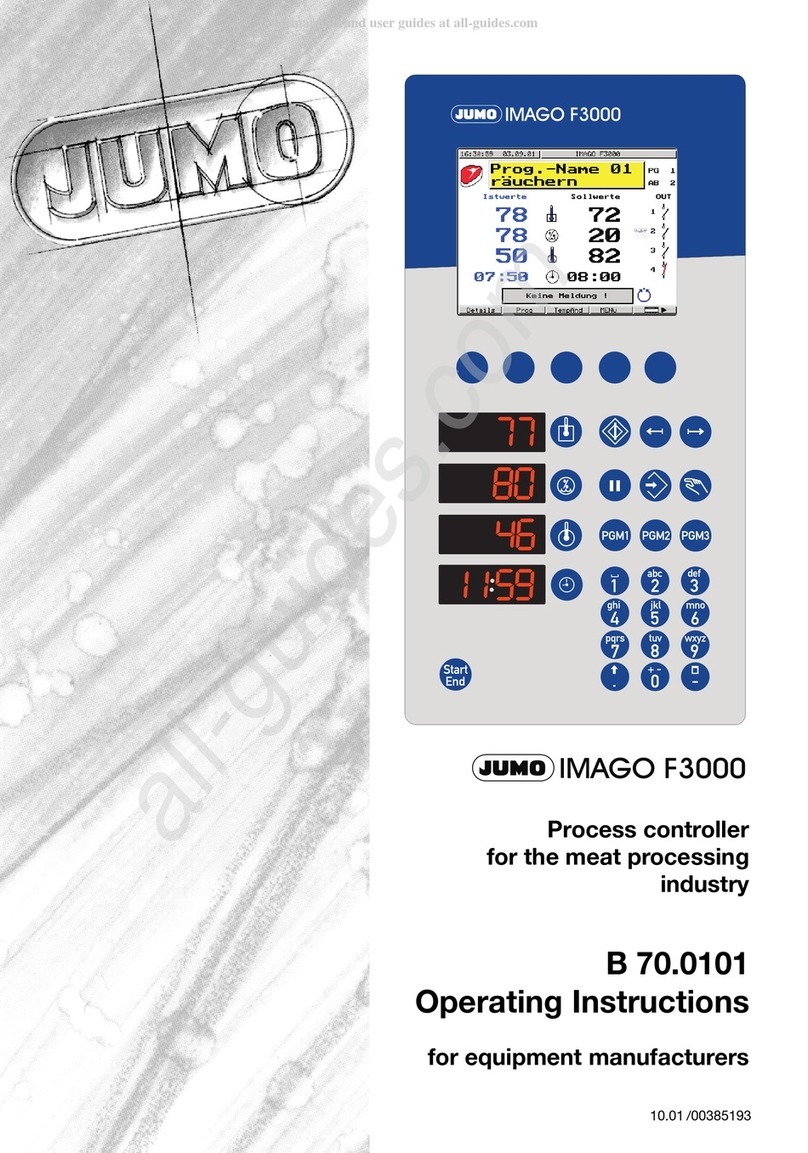
JUMO IMAGO F3000 User manual

/00385193
Process controller
for the meat processing
industry
B 70.0101
Operating Instructions
for equipment manufacturers
10.01


IMAGO F3000 / 10.01
Contents
1 Introduction 5
1.1 Preface .................................................................................................................... 5
1.2 Arrangement of the documentation ..................................................................... 5
1.3 Typographical conventions ................................................................................... 6
1.3.1 Warning signs ........................................................................................................ 6
1.3.2 Note signs .............................................................................................................. 6
1.3.3 Representation ...................................................................................................... 7
2 Identifying the instrument version 9
2.1 Type designation .................................................................................................... 9
2.2 Delivery package .................................................................................................. 10
2.3 Accessories .......................................................................................................... 10
2.4 Plug-in boards for expansion/retrofitting .......................................................... 10
3 Installation 11
3.1 Dimensions ........................................................................................................... 11
3.2 Mounting ............................................................................................................... 12
4 Electrical Connection 13
4.1 Installation notes .................................................................................................. 13
4.2 Connection diagram ............................................................................................ 14
4.2.1 I/O module (slot 1) ............................................................................................... 14
4.2.2 I/O module (slot 2) ............................................................................................... 15
4.2.3 Logic module (slot 3) ........................................................................................... 15
4.2.4 Universal interface (slot 3) ................................................................................... 16
4.2.5 Relay module (slot 4) ........................................................................................... 16
4.2.6 Relay module (slot 5) ........................................................................................... 16
4.2.7 Logic module (slot 6) ........................................................................................... 17
4.2.8 Relay module (slot 6) ........................................................................................... 17
4.2.9 Connector 13 ....................................................................................................... 17
4.2.10 Connector 14 ....................................................................................................... 18
4.2.11 Connector 15 ....................................................................................................... 18
4.2.12 Connector 16 ....................................................................................................... 18
4.3 Electrical isolation ................................................................................................ 19

IMAGO F3000 / 10.01
Contents
5 Instrument Description 21
5.1 Display and control elements ............................................................................. 21
5.1.1 Color screen ........................................................................................................ 23
5.1.2 Keypad for numerical and text entry ................................................................... 24
5.1.3 Freely assignable function keys ........................................................................... 24
5.1.4 LED displays ........................................................................................................ 25
5.1.5 Start/End key ....................................................................................................... 25
5.2 Operating summary ............................................................................................. 26
6 Operation 27
6.1 Basic status .......................................................................................................... 27
6.2 Program design .................................................................................................... 28
6.2.1 General ................................................................................................................ 28
6.2.2 Program entry ...................................................................................................... 29
6.3 Start program ....................................................................................................... 36
6.3.1 Special function: Quick Start ............................................................................... 37
6.4 Automatic operation ............................................................................................ 38
6.4.1 Pause program .................................................................................................... 38
6.4.2 Temporary alterations .......................................................................................... 39
6.5 Manual operation ................................................................................................. 40
6.6 Stop program ........................................................................................................ 41
6.7 Program end signal .............................................................................................. 41
6.8 General .................................................................................................................. 42
6.9 MENU configuration ............................................................................................. 42
6.9.1 Setup interface .................................................................................................... 42
6.9.2 Fieldbus interface ................................................................................................ 42
6.9.3 Analog inputs ....................................................................................................... 43
6.9.4 Controller ............................................................................................................. 43
6.9.5 Core probe ........................................................................................................... 43
6.9.6 Program source ................................................................................................... 43
6.9.7 Process step editor ............................................................................................. 44
6.9.8 Temperature unit .................................................................................................. 44
6.9.9 Password (config) ................................................................................................ 45
6.10 MENU parameterization ...................................................................................... 45
6.10.1 Controller parameter sets .................................................................................... 45
6.10.2 Limit comparators ............................................................................................... 45

IMAGO F3000 / 10.01
Contents
6.10.3 Smoke generator ................................................................................................. 45
6.10.4 Self-optimization .................................................................................................. 45
6.10.5 Password (parameter) .......................................................................................... 45
6.11 User data ............................................................................................................... 46
6.11.1 Contrast ............................................................................................................... 46
6.11.2 Display ................................................................................................................. 46
6.11.3 Instrument data ................................................................................................... 46
6.12 MENU counter ...................................................................................................... 46
6.13 MENU instrument access .................................................................................... 46
6.14 Plug & Play (P&P) .................................................................................................. 47
6.14.1 Write data to P&P memory .................................................................................. 49
6.14.2 Activate automatic save ...................................................................................... 49
6.14.3 Activate/de-activate write protection .................................................................. 50
6.14.4 Copying programs ............................................................................................... 52
6.14.5 Replacing a faulty instrument .............................................................................. 53
6.14.6 Retrofitting a P&P memory .................................................................................. 54
6.14.7 Making a backup copy ........................................................................................ 54
6.14.8 Commissioning a new instrument ....................................................................... 54
6.14.9 P&P memory, programming by OEM .................................................................. 54
6.14.10 Loading data for a write-protected P&P memory on site .................................... 54
6.14.11 Load new instrument software ............................................................................ 55
6.15 Instrument-only settings ..................................................................................... 56
7SetupProgram 57
7.1 Selectors ............................................................................................................... 58
7.2 Process steps ....................................................................................................... 60
7.2.1 List of the process steps ..................................................................................... 60
7.2.2 Editing process steps .......................................................................................... 61
7.3 Screen representation ......................................................................................... 63
7.4 Configuration ........................................................................................................ 63
7.4.1 Interfaces ............................................................................................................. 63
7.4.2 Special settings in interface operation with mTRON modules ............................ 63
7.4.3 Analog inputs ....................................................................................................... 64
7.4.4 Controller ............................................................................................................. 65
7.4.5 Core changeover ................................................................................................. 67
7.4.6 Program source ................................................................................................... 68
7.5 Parameterization .................................................................................................. 70

IMAGO F3000 / 10.01
Contents
7.5.1 Controller parameters .......................................................................................... 70
7.5.2 Limit comparators ............................................................................................... 71
7.5.3 Smoke generator ................................................................................................. 73
7.6 User data ............................................................................................................... 74
7.6.1 Screen saver ........................................................................................................ 74
7.6.2 Instrument data ................................................................................................... 74
7.7 Setup-only settings .............................................................................................. 75
7.7.1 7-segment displays ............................................................................................. 75
7.7.2 Function keys ...................................................................................................... 75
7.7.3 Texts .................................................................................................................... 76
7.7.4 Names ................................................................................................................. 77
7.7.5 Analog outputs .................................................................................................... 77
7.7.6 Assignment of the relay outputs .......................................................................... 78
7.7.7 Logic and alarm functions ................................................................................... 79
7.7.8 Fan control ........................................................................................................... 82
7.7.9 Math/logic ............................................................................................................ 83
7.7.10 Software locks ..................................................................................................... 87
7.7.11 Operating hours counter ..................................................................................... 87
7.7.12 Production data ................................................................................................... 88
7.8 Setup data info ..................................................................................................... 88

IMAGO F3000 / 10.01 5
1 Introduction
1.1 Preface
Version These instructions are valid for the software version: 152.00.19
The version can be called up under MENU ➔Configuration ➔ User data ➔
Instrument data
Warranty
Technical
data Technical data can be found on the Internet at: www.jumo.net
Products ➔Electronic controllers ➔ Programmers ➔ JUMO Imago F3000
Electrostatic
discharge
1.2 Arrangement of the documentation
Operating
Instructions
B 70.0101
These operating instructions are addressed to equipment manufacturers
(OEMs) who have had appropriate professional training. In addition to installa-
tion and electrical connection, they also include all the information required for
commissioning the instrument and setting its parameters.
Expanding /
retrofitting
B 70.0101.5.1
These instructions will be included in the package if accessory modules are
ordered at a later date.
They contain information on installing the modules and safety procedures for
internal operations within the equipment.
HIf any difficulties should arise during commissioning, please do not
make any unauthorized manipulations to the instrument. This could
endanger your rights under the instrument warranty. In such a
case, please contact your local representative or the main factory.
EWhen returning instrument modules, assemblies or components,
the rules of EN 100 015 “Protection of electrostatically sensitive
components” must be observed. Use only the appropriate ESD
packaging for transport. Please note that we cannot accept any
liability for damage caused by ESD (electrostatic discharge).
BPlease read these operating instructions before commissioning the
equipment. Keep the operating instructions in a place that is
accessible to all users at all times.
Please help us to improve these instructions where necessary.
Phone: +49 661 6003 - 0
Fax: +49 661 6003 - 607

1 Introduction
6 IMAGO F3000 / 10.01
1.3 Typographical conventions
1.3.1 Warning signs
Danger
Caution
ESD
1.3.2 Note signs
Note
Reference
Footnote
Instructions for
action
VThis sign is used where there may be danger to personnel if the
instructions are ignored or not followed correctly!
AThis sign is used where there may be damage to equipment or
data if the instructions are ignored or not followed correctly!
EThis sign is used where precautionary measures must be taken for
handling electrostatically sensitive components.
HThis sign is used where your special attention is drawn to a com-
ment.
vThis sign refers to additional information in other manuals, chap-
ters or sections.
abc1Footnotes are remarks that refer to specific points in the text.
Footnotes consist of two parts:
A marker in the text, and the footnote text itself.
The markers in the text are arranged as continuous superscript
numbers.
hThis sign marks the description of a required action. The individual
steps are indicated by this asterisk, e.g.
hInsert the instrument into the panel cut-out from the front.

IMAGO F3000 / 10.01 7
1 Introduction
1.3.3 Representation
Softkeys
and their
operation
Menu items
Keys are shown as they appear on the color screen in the bottom
line. They are labeled by symbols or texts.
If a key has a multiple function, then the text used it that which
corresponds to the function at the moment.
File ➔save as Small arrows between the words indicate a se-
quence of commands to be performed one after
another.

IMAGO F3000 / 10.01 9
2 Identifying the instrument version
2.1 Type designation
The nameplate is glued onto the housing. The type designation that is printed
on it must correspond to the text of the order.
(1) Basic version
700101 JIMAGO F3000
(2) Basic type extension
Format
x 1 332mm x 165mm, portait format
x 2 165mm x 332mm, landscape format
Version
x 8 Standard, with factory settings
x 9 Customized programming according to specification
Language for the configuration level
x 1 German
x 2 English
x 3 French
(3) Slot assignments Slot number
Code Plug-in boards for inputs, outputs, interfaces 123456
0not used - 0 0 - X 0
1Relay module: 10 relay outputs (8 make contacts, 2 changeover) - - - 1 1 X
2Input module: 4 analog inputs, 5 logic inputs for floating contacts 2 X - - - -
3I/O module: 4 analog inputs, 5 logic inputs for floating contacts,
2 analog outputs
X X - - - -
4Logic module: 11 logic inputs for floating contacts, 5 relay outputs (make) - - X - - X
5Universal interface: MODbus (electrically isolated) - - X - - -
6Universal interface: Profibus-DP (electrically isolated) - - X - - -
7Input module: 4 analog inputs, 5 logic inputs for PLC signal levels X X - - - -
8I/O module: 4 analog inputs, 5 logic inputs for PLC signal levels X X - - - -
9Logic module: 11 logic inputs for PLC signal levels, 5 relay outputs (make) - - X - - -
- cannot be assigned
X can be assigned
kstandard assignment
(4) Supply
x23 110 — 240V AC -15/+10%, 48 — 63Hz
x25 20 — 30V AC/DC, 48 — 63Hz
(5) Interface for teleservice and visualization
x00 no interface
x54 Interface RS422/485 (MODbus slave, connector 13)
(6) Extra codes
x000 no extra code
x211 Plug & Play memory
(7) Approvals
x000 none
x061 Underwriters Laboratories Inc. (UL)
(1) (2) (3) (4) (5) (6) (7)
Order code / - - - ,
Order example 700101 /181 -200110 -23 -00 ,000 -000

2 Identifying the instrument version
10 IMAGO F3000 / 10.01
2.2 Delivery package
- Operating Instructions B 70.0101 for the equipment manufacturer
- Operating Instructions B 70.0101.1 for the user
- 4 mounting brackets
2.3 Accessories
Hardware requirements for the setup program:
- PC486DX2-100 or better
- 32 Mbyte RAM
- 15 Mbyte free space on the hard disk
- CD-ROM
- 1 free serial interface
2.4 Plug-in boards for expansion/retrofitting
Product designation Sales No.
Setup program with program editor for Windows 95/98/NT4.0 -
Setup program with program editor and teleservice
for Windows 95/98/NT4.0
-
Program editor -
Interface converter, RS232 to RS422 70/00376969
PC interface cable for setup program,
to connect the instrument to a PC, length 2 m
70/00301315
Relay module: 10 relay outputs (8 make, 2 changeover) -
Input module: 4 analog inputs, 5 logic inputs -
I/O module: 4 analog inputs, 5 logic inputs, 2 analog outputs -
Logic module: 11 logic inputs, 5 relay outputs (make) -
Universal interface: MODbus master (electrically isolated) -
Universal interface: Profibus-DP (electrically isolated) -
Plug & Play memory -
Plug-in boards for expansion/retrofitting Sales No.
Relay module: 10 relay outputs (8 make, 2 changeover) 70/00398349
Input module: 4 analog inputs, 5 logic inputs 70/00398351
I/O module: 4 analog inputs, 5 logic inputs,
2 analog outputs
70/00398352
Logic module: 11 logic inputs, 5 relay outputs (make contacts) 70/00398350
Interface for teleservice and visualization,
RS422/485 (MODbus slave)
70/00398353

3 Installation
12 IMAGO F3000 / 10.01
3.2 Mounting
Front panel
cut-out
h(1) Insert the instrument from the front into the front panel cut-out
h(2) From the back of the panel, push the mounting brackets into the guide
slots on the sides of the housing
h(3) Use a screwdriver to tighten up the mounting brackets evenly
Close mounting If several instruments are mounted in the same front panel, either above one
another or side-by-side, then a minimum spacing of 35 mm must be allowed
between each cut-out in the panel.
Care of the
front panel The front panel can be cleaned with normal commercial detergents and clean-
ing agents. It is resistant to organic solvents (such as ethyl alcohol, turpentine
substitute, P1, xylol and the like).
AIt is not resistant to corrosive acids or lyes, abrasives, or cleaning
with high-pressure cleaners!

IMAGO F3000 / 10.01 13
4 Electrical Connection
4.1 Installation notes
■The choice of cable material, the installation and the electrical connections
to the equipment must meet the requirements of VDE 0100 “Regulations on
the Installation of Power Circuits with Nominal Voltages below 1000V”, or
the appropriate local regulations.
■Work inside the equipment must only be carried out to the extent described
and, like the electrical connections, must only be performed by qualified
personnel.
■If it is possible to make bodily contact with live parts while working on the
equipment, it must be completely (2-pole) isolated from the supply.
■The electromagnetic compatibility (EMC) conforms to the standards and
regulations cited under Technical Data.
vData Sheet T 70.0101
■All input and output cables which are not connected to the supply network
must be implemented as twisted and shielded cables. The shield must be
grounded at one end.
■As far as possible, do not run input and output cabling close to current-
carrying components or cables, but route them separately and not parallel
to such cables.
■Inductive loads in the vicinity of the equipment, such as contactors or
solenoid valves, should be fitted with RC modules for interference
suppression.
■Earth the equipment to the protective earth at the PE terminal. The earthing
cable must have the same conductor cross-section as the power supply
cables.
■Earth/ground cables must be routed in a star configuration to a common
earthing point that is connected to the protective earth of the supply
installation.
Earth cables must not be looped (“daisy-chained”), i.e. they must not be
routed through one piece of equipment after another.
■Do not connect any additional loads to the supply terminals of the
equipment.
■The equipment is not suitable for installation in Ex areas (areas with an
explosion hazard).
A

4 Electrical Connection
14 IMAGO F3000 / 10.01
4.2 Connection diagram
V
The electrical connections must only be made by qualified personnel.
4.2.1 I/O module (slot 1)
Analog input No. 1 2 3 4 Symbol
Thermocouple 1 +
3 -
4 +
6 -
7 +
9 -
10 +
12 -
Resistance
thermometer
1(a)
2(b)
3(c)
4(a)
5(b)
6(c)
7(a)
8(b)
9(c)
10 (a)
11 (b)
12 (c)
Current input
0(4) — 20mA
2 +
3-
5+
6 -
8 +
9 -
11 +
12 -
Voltage input
0(2) — 10V
1 +
3 -
4 +
6 -
7 +
9 -
10 +
12 -
Logic input No. 1 2345Symbol
Floating contact, or
PLC input
24V DC
LO level: -30 to +6V
HI level: 13 to 30V
13 S
18 P
13 +
18 COM
14 S
18 P
14 +
18 COM
15 S
18 P
15 +
18 COM
16 S
18 P
16 +
18 COM
17 S
18 P
17 +
18 COM
Analog output No. 1 2 Symbol
0(4) — 20mA
0(2) — 10V
configurable
19 +
20 -
21 +
22 -

IMAGO F3000 / 10.01 15
4 Electrical Connection
4.2.2 I/O module (slot 2)
4.2.3 Logic module (slot 3)
Analog input No. 5 6 7 8 Symbol
Thermocouple 23 +
25 -
26 +
28 -
29 +
31 -
32 +
34 -
Resistance
thermometer
23 (a)
24 (b)
25 (c)
26 (a)
27 (b)
28 (c)
29 (a)
30 (b)
31 (c)
32 (a)
33 (b)
34 (c)
Current input
0(4) — 20mA
24 +
25-
27 +
28 -
30 +
31 -
33 +
34 -
Voltage input
0(2) — 10V
23 +
25 -
26 +
28 -
29 +
31 -
32 +
34 -
Logic input No. 6 7 8 9 10 Symbol
Floating contact,
or
PLC input: 24V DC
LO level: -30 to +6V
HI level: +13 to +30V
35 S
40 P
35 +
40 COM
36 S
40 P
36 +
40 COM
37 S
40 P
37 +
40 COM
38 S
40 P
38 +
40 COM
39 S
40 P
39 +
40 COM
Analog output No. 3 4 Symbol
0(4) — 20mA
0(2) — 10V
configurable
41 +
42 -
43 +
44 -
Logic input No. 22 23 24 25 26 27 28 29 30 31 32 Symbol
Floating contact,
or
PLC input: 24V DC
LO level: -30 to +6V
HI level: +13 to +30V
45 S
56 P
45 +
56 COM
46 S
56 P
46 +
56 COM
47 S
56 P
47 +
56 COM
48 S
56 P
48 +
56 COM
49 S
56 P
49 +
56 COM
50 S
56 P
50 +
56 COM
51 S
56 P
51 +
56 COM
52 S
56 P
52 +
56 COM
53 S
56 P
53 +
56 COM
54 S
56 P
54 +
56 COM
55 S
56 P
55 +
56 COM
Relay output No. 31 32 33 34 35 Symbol
3A 230V 57 P
58 S
59 P
60 S
61 P
62 S
63 P
64 S
65 P
66 S

4 Electrical Connection
16 IMAGO F3000 / 10.01
4.2.4 Universal interface (slot 3)
4.2.5 Relay module (slot 4)
4.2.6 Relay module (slot 5)
Connection for Assignment PROFIBUS-DP Symbol
RS422 interface,
electrically isolated
4 RxD (+)
9 RxD (-)
3 TxD (+)
8 TxD (-)
5 GND
8 A(+)
3 B(-)
6 VCC
5 GND
9 GND
RS485 interface,
electrically isolated
3 RxD/TxD A(+)
8 RxD/TxD B(-)
5 GND
Relay output No. 1 2 3 4 5 Symbol
3A 230V 67 P
68 O
69 S
70 P
71 O
72 S
73 P
74 S
75 P
76 S
77 P
78 S
Relay output No. 6 7 8 9 10 Symbol
3A 230V 79 P
80 S
81 P
82 S
83 P
84 S
85 P
86 S
87 P
88 S
Relay output No. 11 12 13 14 15 Symbol
3A 230V 89 P
90 O
91 S
92 P
93 O
94 S
95 P
96 S
97 P
98 S
99 P
100 S
Relay output No. 16 17 18 19 20 Symbol
3A 230V 101 P
102 S
103 P
104 S
105 P
106 S
107 P
108 S
109 P
110 S

IMAGO F3000 / 10.01 17
4 Electrical Connection
4.2.7 Logic module (slot 6)
4.2.8 Relay module (slot 6)
4.2.9 Connector 13
Logic input No. 11 12 13 14 15 16 17 18 19 20 21 Symbol
Floating contact,
or
PLC input: DC 24V
LO level: -30 to +6V
HI level: +13 to +30V
111 S
122 P
111 +
122 COM
112 S
122 P
112 +
122 COM
113 S
122 P
113 +
122 COM
114 S
122 P
114 +
122 COM
115 S
122 P
115 +
122 COM
116 S
122 P
116 +
122 COM
117 S
122 P
117 +
122 COM
118 S
122 P
118 +
122 COM
119 S
122 P
119 +
122 COM
120 S
122 P
120 +
122 COM
121 S
122 P
121 +
122 COM
Relay output No. 26 27 28 29 30 Symbol
3A 230V 123 P
124 S
125 P
126 S
127 P
128 S
129 P
130 S
131 P
132 S
Relay output No. 21 22 23 24 25 Symbol
3A 230V 111 P
112 O
113 S
114 P
115 O
116 S
117 P
118 S
119 P
120 S
121 P
122 S
Relay output No. 26 27 28 29 30 Symbol
3A 230V 123 P
124 S
125 P
126 S
127 P
128 S
129 P
130 S
131 P
132 S
Teleservice,
visualization
RS 422 RS 485 Symbol
RS422/485 interface 4 RxD (+)
9 RxD (-)
3 TxD (+)
8 TxD (-)
8 RxD/TxD B(-)
3 RxD/TxD A(+)
5 GND 5 GND

4 Electrical Connection
18 IMAGO F3000 / 10.01
4.2.10 Connector 14
4.2.11 Connector 15
4.2.12 Connector 16
Connection for Picture Symbol
Plug & Play interface
Connection for Diagram Symbol
Setup connector PC interface with TTL/RS232 converter
Connection Assignment Symbol
Supply voltage,
as per nameplate
L1 phase/line
N neutral
PE protective earth
Other manuals for IMAGO F3000
1
Table of contents
Other JUMO Controllers manuals

JUMO
JUMO eTron M 100 User manual

JUMO
JUMO dTRANS CR 02 User manual

JUMO
JUMO DICON 401 User manual

JUMO
JUMO DICON touch User manual

JUMO
JUMO TYA 202 User manual

JUMO
JUMO AQUIS 500 AS User manual

JUMO
JUMO IMAGO 500 User manual

JUMO
JUMO IMAGO 500 User manual

JUMO
JUMO cTRON 04 User manual

JUMO
JUMO DICON touch User manual

JUMO
JUMO diraTRON Series User manual

JUMO
JUMO dTRON 16.1 B 70.3011 User manual

JUMO
JUMO AQUIS 500 RS User manual

JUMO
JUMO IMAGO 500 User manual

JUMO
JUMO dTRANS pH 02 User manual

JUMO
JUMO cTRON 04 User manual

JUMO
JUMO DICON touch User manual

JUMO
JUMO TYA S202 User manual

JUMO
JUMO DICON touch User manual

JUMO
JUMO TYA S201 User manual