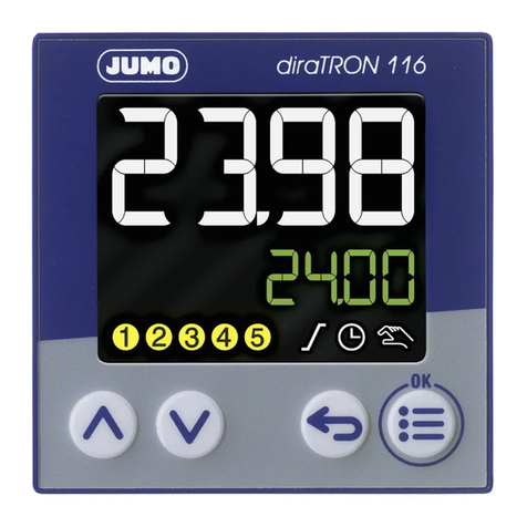
JUMO diraTRON Series User manual

70211000T92Z001K000
V3.00/EN/00688816/2019-10-15
JUMO diraTRON/diraVIEW 104/108/116/132
Compact controller/digital indicator
Interface Description


Contents
Contents
1 Introduction . . . . . . . . . . . . . . . . . . . . . . . . . . . . . . . . . . . . . . . . . . . . . . . . . 5
1.1 Safety information . . . . . . . . . . . . . . . . . . . . . . . . . . . . . . . . . . . . . . . . . . . . . . . . . . . . . . . . .5
1.2 Intended use . . . . . . . . . . . . . . . . . . . . . . . . . . . . . . . . . . . . . . . . . . . . . . . . . . . . . . . . . . . . .5
1.3 Qualification of personnel . . . . . . . . . . . . . . . . . . . . . . . . . . . . . . . . . . . . . . . . . . . . . . . . . . .5
1.4 Content of this document . . . . . . . . . . . . . . . . . . . . . . . . . . . . . . . . . . . . . . . . . . . . . . . . . . .6
2 Interface . . . . . . . . . . . . . . . . . . . . . . . . . . . . . . . . . . . . . . . . . . . . . . . . . . . . 7
3 Modbus protocol description. . . . . . . . . . . . . . . . . . . . . . . . . . . . . . . . . . . 13
3.1 Master-slave principle . . . . . . . . . . . . . . . . . . . . . . . . . . . . . . . . . . . . . . . . . . . . . . . . . . . . . .13
3.2 Transmission mode. . . . . . . . . . . . . . . . . . . . . . . . . . . . . . . . . . . . . . . . . . . . . . . . . . . . . . . .13
3.3 Chronological sequence of communication . . . . . . . . . . . . . . . . . . . . . . . . . . . . . . . . . . . . .14
3.4 Structure of a Modbus telegram . . . . . . . . . . . . . . . . . . . . . . . . . . . . . . . . . . . . . . . . . . . . . .15
3.5 Device address (RS485). . . . . . . . . . . . . . . . . . . . . . . . . . . . . . . . . . . . . . . . . . . . . . . . . . . .16
3.6 Function codes . . . . . . . . . . . . . . . . . . . . . . . . . . . . . . . . . . . . . . . . . . . . . . . . . . . . . . . . . . .16
3.6.1 Reading n words . . . . . . . . . . . . . . . . . . . . . . . . . . . . . . . . . . . . . . . . . . . . . . . . . . . . . . . . . .17
3.6.2 Writing one word . . . . . . . . . . . . . . . . . . . . . . . . . . . . . . . . . . . . . . . . . . . . . . . . . . . . . . . . . .18
3.6.3 Writing n words . . . . . . . . . . . . . . . . . . . . . . . . . . . . . . . . . . . . . . . . . . . . . . . . . . . . . . . . . . .19
3.7 Transmission formats . . . . . . . . . . . . . . . . . . . . . . . . . . . . . . . . . . . . . . . . . . . . . . . . . . . . . .20
3.7.1 Integer values . . . . . . . . . . . . . . . . . . . . . . . . . . . . . . . . . . . . . . . . . . . . . . . . . . . . . . . . . . . .20
3.7.2 Float values. . . . . . . . . . . . . . . . . . . . . . . . . . . . . . . . . . . . . . . . . . . . . . . . . . . . . . . . . . . . . .20
3.8 Checksum (CRC16) . . . . . . . . . . . . . . . . . . . . . . . . . . . . . . . . . . . . . . . . . . . . . . . . . . . . . . .22
3.9 Error messages. . . . . . . . . . . . . . . . . . . . . . . . . . . . . . . . . . . . . . . . . . . . . . . . . . . . . . . . . . .23
3.9.1 Modbus error codes . . . . . . . . . . . . . . . . . . . . . . . . . . . . . . . . . . . . . . . . . . . . . . . . . . . . . . .23
3.9.2 Error messages for invalid values. . . . . . . . . . . . . . . . . . . . . . . . . . . . . . . . . . . . . . . . . . . . .24
4 Modbus addresses . . . . . . . . . . . . . . . . . . . . . . . . . . . . . . . . . . . . . . . . . . . 25
4.1 Data types and access types . . . . . . . . . . . . . . . . . . . . . . . . . . . . . . . . . . . . . . . . . . . . . . . .25
4.2 Addresses . . . . . . . . . . . . . . . . . . . . . . . . . . . . . . . . . . . . . . . . . . . . . . . . . . . . . . . . . . . . . . .26
4.2.1 Configuration data. . . . . . . . . . . . . . . . . . . . . . . . . . . . . . . . . . . . . . . . . . . . . . . . . . . . . . . . .26
4.2.2 Commands . . . . . . . . . . . . . . . . . . . . . . . . . . . . . . . . . . . . . . . . . . . . . . . . . . . . . . . . . . . . . .31
4.2.3 Process values . . . . . . . . . . . . . . . . . . . . . . . . . . . . . . . . . . . . . . . . . . . . . . . . . . . . . . . . . . .33

Contents

5
1 Introduction
1 Introduction
1.1 Safety information
General
This manual contains information that must be observed in the interest of your own safety and to avoid
material damage. This information is supported by symbols which are used in this manual as indicated.
Please read this manual before starting up the device. Store this manual in a place that is accessible to
all users at all times.
If difficulties occur during startup, please do not intervene in any way that could jeopardize your warranty
rights!
Warning symbols
CAUTION!
This symbol in connection with the signal word indicates that material damage or data loss will occur
if the respective precautionary measures are not taken.
Note symbols
NOTE!
This symbol refers to important information about the product, its handling, or additional benefits.
1.2 Intended use
The device is designed for use in an industrial environment as specified in the technical data. Other uses
beyond those defined are not viewed as intended uses.
The device has been manufactured in compliance with applicable standards and directives as well as
the applicable safety regulations. Nevertheless, improper use may lead to personal injury or material
damage.
To avoid danger, only use the device:
• For the intended use
• When in good order and condition
• When taking the technical documentation provided into account
Risks resulting from the application may arise, e.g. as the result of missing safety provisions or wrong
settings, even when the device is used properly and as intended.
1.3 Qualification of personnel
This document contains the necessary information for the intended use of the device to which it relates.
It is intended for staff with technical qualifications who have been specially trained and have the appro-
priate knowledge in the field of automation technology.
The appropriate level of knowledge and the technically fault-free implementation of the safety informa-
tion and warnings contained in the technical documentation provided are prerequisites for risk-free
mounting, installation, and startup as well as for ensuring safety when operating the described modules.
Only qualified personnel have the required specialist knowledge to correctly interpret and implement the
safety information and warnings contained in this document in specific situations.
REFERENCE!
This symbol refers to additional information in other sections, chapters, or other manuals.

1 Introduction
6
1.4 Content of this document
NOTE!
This document applies to devices from the device series 70211x (compact controllers) as well as to de-
vices from the device series 70151x (digital indicators).
This document describes the use of the RS485 interface or the Ethernet interface as a Modbus slave in
the operating modes Modbus-RTU or Modbus-TCP or Modbus-RTU/ASCII via TCP/IP. After a short in-
troduction to the Modbus protocol, the addresses of all the configuration data, commands, and process
values accessible via Modbus will be listed.
In addition to this document, the operating manual of the respective device series must be observed:
• Types 701510, 701511, 701512, 701513, 701514 (digital indicators):
Document 70151000T90Z...K...
• Types 702110, 702111, 702112, 702113, 702114 (compact controllers):
Document 70211000T90Z...K...

7
2 Interface
2Interface
There is an option to equip the device with an RS485 interface or an Ethernet interface.
RS485 interface
NOTE!
A twisted connecting cable with shielding must be used to connect the RS485 interface.
To avoid transmission errors, only the signals listed above and, if necessary, GND may be routed in the
connecting cable.
NOTE!
To ensure fault-free operation, terminating resistors are required at the beginning and end of an RS485
transmission path.
For further information on electrical connection and configuration of the interface, please refer to the op-
erating manual of the device.
Ethernet interface
NOTE!
To connect the Ethernet interface, use a network cable that at least corresponds to the CAT 5 category.
Within the device, the communication is converted from Ethernet to the serial interface. The protocol
used via Ethernet (Modbus-TCP or Modbus-RTU/ASCII via TCP) is automatically detected. A configu-
ration of the serial interface is not necessary (baud rate and data format are fixed).
The settings of the Ethernet interface must be made with the Lantronix CPR Manager PC software from
the manufacturer Lantronix, Inc. This software is available for download at the following link:
https://www.lantronix.com/products/com-port-redirector
Version
for type 701510 (format 132)
Symbol and termi-
nal designation
Version
for types 701511 to 701514
Symbol and termi-
nal designation
Option 1:
RS485 interface
11 Option 1 (alternative to digital
output 4):
RS485 interface
11
12 12
RxD/TxD+
RxD/TxD-
RxD/TxD+
RxD/TxD-
Version
for type 702110 (format 132)
Symbol and termi-
nal designation
Version
for types 702111 to 702114
Symbol and termi-
nal designation
Option 1:
RS485 interface
11 Option 1 (alternative to digital
output 4):
RS485 interface
11
12 12
RxD/TxD+
RxD/TxD-
RxD/TxD+
RxD/TxD-

2 Interface
8
Configuration of the Ethernet interface
Prerequisite: The Lantronix CPR Manager PC software has been installed and started.
1. Start screen
Click OK on the start screen.
The "CPR Manager ..." window opens.
2. Search for device
Click on „Search For Devices“.
The device found is listed in the Device List.
3. Start the web interface of the device
If several devices were found, the device can be identified by the MAC address in the "HW Address"
column. The MAC address is indicated on the nameplate of the device.
Move the mouse pointer to the found device in the device list and select the menu item "Launch Web
Interface for Device" in the context menu (right mouse button).
The web interface starts in the web browser.
4. The first time, the user name and password are requested.
Leave both input fields empty and click OK.
The Device Status window opens.
5. The Device Status window displays the current settings of the device.

9
2 Interface
Click on the menu item "Network" in the left column.
The Network Settings window opens.
6. The Network Settings window displays the current network settings of the device.
Under "IP Configuration", assign a fixed IP address for the device and enter the subnet mask. Con-
firm the settings with OK.
In the left column, click on the menu item "Channel 1 - Serial Settings".
The Serial Settings window of channel 1 opens.
7. In the Serial Settings window, the current settings of channel 1 are displayed.

2 Interface
10
If necessary, change the values under "Port Settings" so that they match the settings in this figure.
Confirm the settings with OK.
In the left column, click on the menu item "Channel 1 - Connection".
The Connection Settings window of Channel 1 opens.
8. The Connection Settings window displays the current settings of channel 1.
Under "Endpoint Configuration", enter the IP address of the Modbus master in the "Remote Host"
field. Enter the port number 502 in the two fields "Local Port" and "Remote Port". Confirm the settings
with OK..
All necessary settings have been made.
9. In the left column, click on the menu item "Apply Settings"
The settings are stored in the device.

11
2 Interface
NOTE!
The communication should be tested with a suitable PC program, e.g. the Modbus Poll program
(https://www.modbustools.com/download.html).

2 Interface
12

13
3 Modbus protocol description
3.1 Master-slave principle
Communication between a master and a slave device with Modbus takes place according to the master/
slave principle in the form of data request/instruction – response.
The master controls the data exchange; the slaves only have a response function. They are identified
by their device address.
NOTE!
This device can only be operated as a Modbus slave.
The Modbus master can read and write different device data, configuration parameters, and device pro-
cess values. Refer to the Modbus address tables for details.
chapter 4 "Modbus addresses", Page 25
3.2 Transmission mode
RS485
RTU mode (Remote Terminal Unit) is used as the transmission mode. The transmission of a character
is therefore performed in binary format with 8 data bits, 1 start bit, 1 or 2 stop bits, and, if necessary, 1
parity bit (see data format). The highest value bit (MSB, most significant bit) is transmitted first.
The ASCII operating mode is not supported.
Ethernet
Via Ethernet, the protocols Modbus-TCP and Modbus-RTU/ASCII via TCP/IP are supported, whereby
the protocol used is automatically recognized. A character is transmitted exclusively with 8 data bits, 1
start bit and 1 stop bit (8-1-no parity; see data format).
Data format
The data format describes the structure of a transmitted character.
Master
Slave 1 Slave 2 Slave n
Data format (con-
figuration)
Start bit Data bits Parity bit Stop bit Number of
bits
8 - 1 - no parity180110
8 - 1 - odd parity181111
8 - 1 - even parity181111
8 - 2 - no parity180211

3 Modbus protocol description
14
3.3 Chronological sequence of communication
Character transmission time
The character transmission time (time taken to transmit one character with 8 data bits) depends on the
baud rate and the number of bits of the character (see table for data format):
Time diagram of a data request
A data request runs according to the following time diagram:
The data request and response consist of several characters (each with a start bit, 8 data bits, a parity
bit if necessary, and a stop bit) which are transmitted coherently.
NOTE!
The waiting periods t1 and t2 also contain the end identifier (3.5 × character transmission time), which
follows after each data request or response.
NOTE!
In the configuration of the serial interface of the device, a minimum response time can be set
(0 to 500 ms). This set time is the minimum waiting period before a response is transmitted. If a smaller
value is set, then the response time may be longer than the preset value (internal processing takes lon-
ger); the controller responds as soon as internal processing is completed. The preset time of 0 ms
Character transmission time [ms] = 1000 × number of bits/baud rate
Baud rate[Bd] Number of bits Character transmission time[ms]
115200 11 0.095
10 0.087
38400 11 0.286
10 0.260
19200 11 0.573
10 0.521
9600 11 1.146
10 1.042
t1The slave has to observe this waiting period before sending the response.
min.: 5 ms
typically: 5to35ms
max.: 35 ms or the minimum response time set in the configuration
t2The master has to observe this waiting period before starting a new data request.
35 ms
Master
Slave
Data request
Response
Data request
t
t1t2

15
3 Modbus protocol description
means that the device responds at the maximum possible speed.
The minimum response time is required by the master in order to switch the interface drivers from trans-
mitting to receiving.
NOTE!
During t1 and t2 and during the response time of the slave, no data requests may be generated by the
master. Requests during t1 and t2 are ignored by the slave. Requests during the response time invalidate
all the data currently on the bus.
3.4 Structure of a Modbus telegram
Modbus-RTU
All telegrams have the same structure:
Each telegram has four fields:
Modbus-TCP
Modbus-TCP is a standardized procedure in which a Modbus telegram is transmitted encapsulated in a
TCP segment via Ethernet. The Modbus telegram (without CRC) is transmitted with an additional 6 or 7
byte MBAP header (Modbus Application Header). The seventh byte corresponds to the first byte of the
Modbus RTU, but here it is called differently.
For comparison: The "normal" Modbus telegram:
Slave address Function code Data field Checksum
CRC
1 byte 1 byte x bytes 2 bytes
Slave address Device address of a specific slave
Function code Function selection (read/write words)
Data field Contains information (according to the function code)
• Word address
• Number of words
• Word value(s)
Checksum Detection of transmission errors
MBAP header Modbus telegram
2 bytes
Transaction ID
2 bytes
Protocol ID
2 bytes
Length
1 byte
Unit ID
Additional bytes as below,
however, without CRC
Identical in re-
quest and re-
sponse
Must be 0 for
Modbus
Length of re-
quest/re-
sponse in
bytes starting
with (incl.)
"Unit ID"
Corresponds to
device address
and must be TCP
0xFF or 0 (0 =
broadcast)
Slave
Address
1 byte
Function code
1 byte
Data field
x bytes
CRC16
2 bytes

3 Modbus protocol description
16
Modbus-RTU/ASCII via TCP/IP
With Modbus-RTU/ASCII via TCP/IP the MBAP header is omitted, the entire Modbus telegram (with
CRC) is transmitted via TCP.
3.5 Device address (RS485)
The device address can be set to between 1DEC and 254DEC. Each Modbus station must have a unique
device address.
The following data exchange variants are available for accessing the connected stations:
Query
This is a data request/instruction from the master to a slave via the corresponding device address
(1 to 254). The addressed slave responds.
Broadcast
The broadcast is an instruction from the master to all slaves via the device address 0 (for example, to
transmit a certain value to all slaves).
The connected slaves do not respond. In such a case, the correct acceptance of the value by the slaves
should be checked by a subsequent readout at each individual slave. A data request using the device
address 0 is meaningless.
NOTE!
A maximum of 31 slaves can be accessed via the RS485 interface.
The device address 0 is reserved as a Modbus broadcast address:
an instruction from the master to address 0 is executed by all slaves, however, none of the slaves re-
spond (since it would otherwise lead to a data collision).
The address is given in binary format in the transmission protocol.
3.6 Function codes
Function overview
The functions described in the following are available for the readout of measured values, device data,
and process data, as well as for writing specific data.
NOTE!
A hexadecimal number is marked by a preceding "0x".
Example: 0x0010 (= 16DEC)
NOTE!
If the device does not respond to these functions or generates an error code, these can be evaluated.
chapter 3.9 "Error messages", Page 23
Function code Function Limit
0x03 or 0x04 Reading n words Max. 127 words (254 bytes)
0x06 Writing one word Max. 1 word (2 bytes)
0x10 Writing n words Max. 127 words (254 bytes)

17
3 Modbus protocol description
3.6.1 Reading n words
This function is used to read n words starting at a specific address.
Data request
Response
Example
Read measured value (here: 25.0) from the analog input (from word address 0x7000, 4 bytes = 2 words):
chapter 3.7.2 "Float values", Page 20
chapter 3.8 "Checksum (CRC16)", Page 22
Slave address Function
0x03 or 0x04
Address of
first word
Number of words Checksum CRC
1 byte 1 byte 2 bytes 2 bytes 2 bytes
Slave address Function
0x03 or 0x04
Number
of bytes read
Word value(s) Checksum CRC
1 byte 1 byte 1 byte x bytes 2 bytes
Data request:
01 03 70 00 00 02 DE CB
Slave Function Address of
1st word
Number of words CRC
Response (measured value in Modbus floating-point format):
01 03 04 00 00 41 C8 CB F5
Slave Function Bytes
read
Measured value CRC

3 Modbus protocol description
18
3.6.2 Writing one word
This function is used to write one word to a specific address.
The data blocks are identical for the instruction and response.
Instruction
Response
Example
Write binary value 1 to the external digital input 1 (word address 0x37A1):
chapter 3.8 "Checksum (CRC16)", Page 22
Slave address Function
0x06
Word address Word value Checksum CRC
1 byte 1 byte 2 bytes 2 bytes 2 bytes
Slave address Function
0x06
Word address Word value Checksum
CRC
1 byte 1 byte 2 bytes 2 bytes 2 bytes
Instruction:
01 06 37 A1 00 01 17 9C
Slave Function Word address Value CRC
Response:
01 06 37 A1 00 01 17 9C
Slave Function Word address Value CRC

19
3 Modbus protocol description
3.6.3 Writing n words
This function is used to write n words starting at a specific address.
Instruction
Response
Example
Write value 25.0 to the external analog input 1 (from word address 0x3700, 4 bytes = 2 words):
chapter 3.7.2 "Float values", Page 20
chapter 3.8 "Checksum (CRC16)", Page 22
Slave address Function
0x10
Address of
first word
Number of
words
Number of
bytes
Word val-
ue(s)
Checksum
CRC
1 byte 1 byte 2 bytes 2 bytes 1 byte x bytes 2 bytes
Slave address Function
0x10
Address of
first word
Number of
words
Checksum
CRC
1 byte 1 byte 2 bytes 2 bytes 2 bytes
Instruction (value in Modbus floating-point format):
01 10 37 00 00 02 04 00 00 41 C8 B0 58
Slave Function Address of
first word
Number of
words
Number of
bytes
Value CRC
Response:
01 10 37 00 00 02 4F BC
Slave Function Address of
first word
Number of
words
CRC

3 Modbus protocol description
20
3.7 Transmission formats
3.7.1 Integer values
Integer values are transmitted via Modbus in the following sequence:
First the high byte, then the low byte.
Example
In this example, the integer value at address 0x5208 is to be extracted. The value here is to be "4" (word
value 0x0004).
3.7.2 Float values
For floating-point values, Modbus functions with the IEEE 754 standard format (32-bit), but with the dif-
ference that bytes 1 and 2 are interchanged with bytes 3 and 4.
Example
In this example, the measured value of the analog input (from word address 0x7000) is to be extracted.
The value here should be 25.0 (0x41C80000 in IEEE 754 format).
Data request:
01 03 52 08 00 01 15 70
Slave Function Address of
first word
Number of words CRC
Response:
01 03 02 00 04 B9 87
Slave Function Bytes
read
Integer value CRC
Single floating-point format (32-bit) according to standard IEEE 754
SEEEEEEE EMMMMMMM MMMMMMMM MMMMMMMM
Byte 1 Byte 2 Byte 3 Byte 4
S - Prefix sign bit
E - Exponent (two's complement)
M - 23-bit normalized mantissa
Modbus floating-point format
Modbus address x Modbus address x+1
MMMMMMMM MMMMMMMM SEEEEEEE EMMMMMMM
Byte 3 Byte 4 Byte 1 Byte 2
Data request:
01 03 70 00 00 02 DE CB
Slave Function Address of
1st word
Number of words CRC
Response:
01 03 04 00 00 41 C8 CB F5
Slave Function Bytes
read
Measured value as
floating-point value
CRC
This manual suits for next models
9
Table of contents
Other JUMO Controllers manuals

JUMO
JUMO DICON touch User manual

JUMO
JUMO DICON touch User manual

JUMO
JUMO DICON touch User manual

JUMO
JUMO AQUIS 500 RS User manual

JUMO
JUMO cTRON 04 User manual

JUMO
JUMO IMAGO F3000 User manual

JUMO
JUMO dTRON 16.1 B 70.3011 User manual

JUMO
JUMO IMAGO 500 User manual

JUMO
JUMO AQUIS 500 AS User manual

JUMO
JUMO DICON 400 User manual

JUMO
JUMO B 703571.0 User manual

JUMO
JUMO DICON touch User manual

JUMO
JUMO iTRON DR 100 User manual

JUMO
JUMO dTRANS CR 02 User manual

JUMO
JUMO AQUIS 500 pH User manual

JUMO
JUMO diraTRON 104 Reference guide

JUMO
JUMO TYA S201 User manual

JUMO
JUMO AQUIS 500 RS User manual

JUMO
JUMO diraTRON 104 User manual

JUMO
JUMO TYA S202 User manual