1-6 (No.YD010)
2.2 Service position
This unit has been designed so that the Mechanism and Main
board assemblies can be removed together from the chassis as-
sembly. Before diagnosing or servicing the circuit boards, take
out the major parts from the chassis assembly.
2.2.1 How to set the "Service position"
(1) Refer to the disassembly procedure and perform the disas-
sembly of the major parts before removing the Mechanism
assembly.
(2) Remove the screws that fix the Mechanism assembly to
the Chassis assembly. If any other screws are used to fix
the boards, remove them also.
(3) Remove the combined Mechanism and Main board assem-
blies.
(4) If any other major parts are used, remove them also.
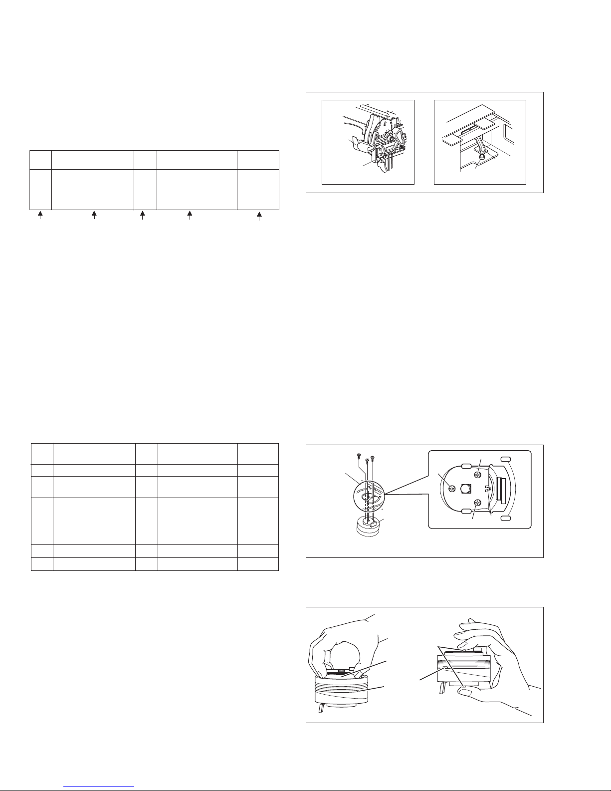
(5) Connect the wires and connectors of the major parts that
have been removed in steps (1) to (4). (Refer to Fig. 2-2a.)
(6) Place the combined Mechanism, Main board and other
board assemblies upside down.
(7) Insert the power cord plug into the power outlet and then
proceed with the diagnostics and servicing of the board as-
sembly.
Notes:
•Before inserting the power cord plug into the power out-
let, make sure that none of the electrical parts are able
to short-circuit between the workbench and the board
assembly.
•For the disassembly procedure of the major parts and
details of the precautions to be taken, see "3.1 Remov-
ing the major parts".
•If there are wire connections from the Main board and
Mechanism assemblies to the other major parts, be sure
to remove them (including wires connected to the major
parts) first before performing step (2).
•When carrying out diagnosis and repair of the Main
board assembly in the "Service position", be sure to
ground both the Main board and Mechanism assem-
blies. If they are improperly grounded, there may be
noise on the playback picture or FDP counter display
may move even when the mechanism is kept in an inop-
erative status.
•In order to diagnose the playback or recording of the cas-
sette tape, set the Mechanism assembly to the required
mode before placing it upside down. If the mechanism
mode is changed (including ejection) while it is in an up-
side down position the tape inside may be damaged.
•For some models, the mechanism and board assem-
blies are attached by connectors only. When carrying
out a diagnosis or repair of the boards in the "Service
position", make sure that the connectors are not dis-
connected.
Fig.2-2a
2.3 Jig RCU mode
This unit uses the following two modes for receiving remote con-
trol codes.
(1) User RCU mode:Ordinary mode for use by the user.
(2) Jig RCU mode: Mode for use in production and servicing.
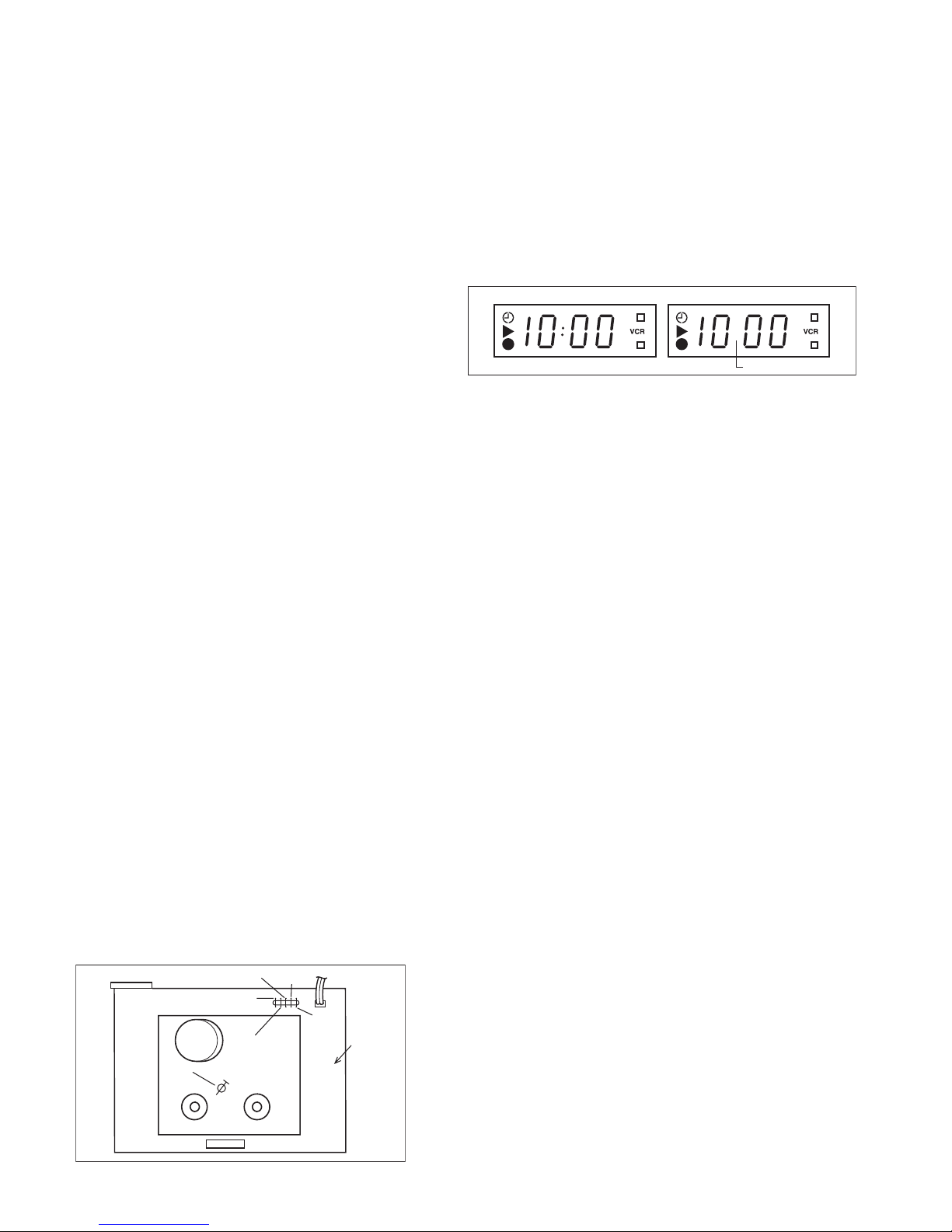
When using the Jig RCU, it is required to set the VCR to the Jig
RCU mode (the mode in which codes from the Jig RCU can be
received). As both of the above two modes are stored in the EE-
PROM, it is required to set the VCR back to the User RCU mode
each time that an adjustment is made or to check that the neces-
sary operations have been completed.These modes can be set
by the operations described below.
2.3.1 Setting the Jig RCU mode
(1) Unplug the power cord plug from the power outlet.
(2) Press and hold the "REC" and "PAUSE" buttons on the
VCR simultaneously, while plugging the power cord plug
into the power outlet.
When the VCR is set to the Jig RCU mode, the symbols
( " : " ) in the time display of the FDP are turned off.
2.3.2 Setting the User RCU mode
(1) Turn off the power.
(2) Press the "REC" and "PAUSE" buttons of the VCR simulta-
neously. Alternatively, transmit the code "80" from the Jig RCU.
2.4 Mechanism service mode
This model has a unique function to enter the mechanism into ev-
ery operation mode without loading of any cassette tape. This
function is called the "Mechanism service mode".
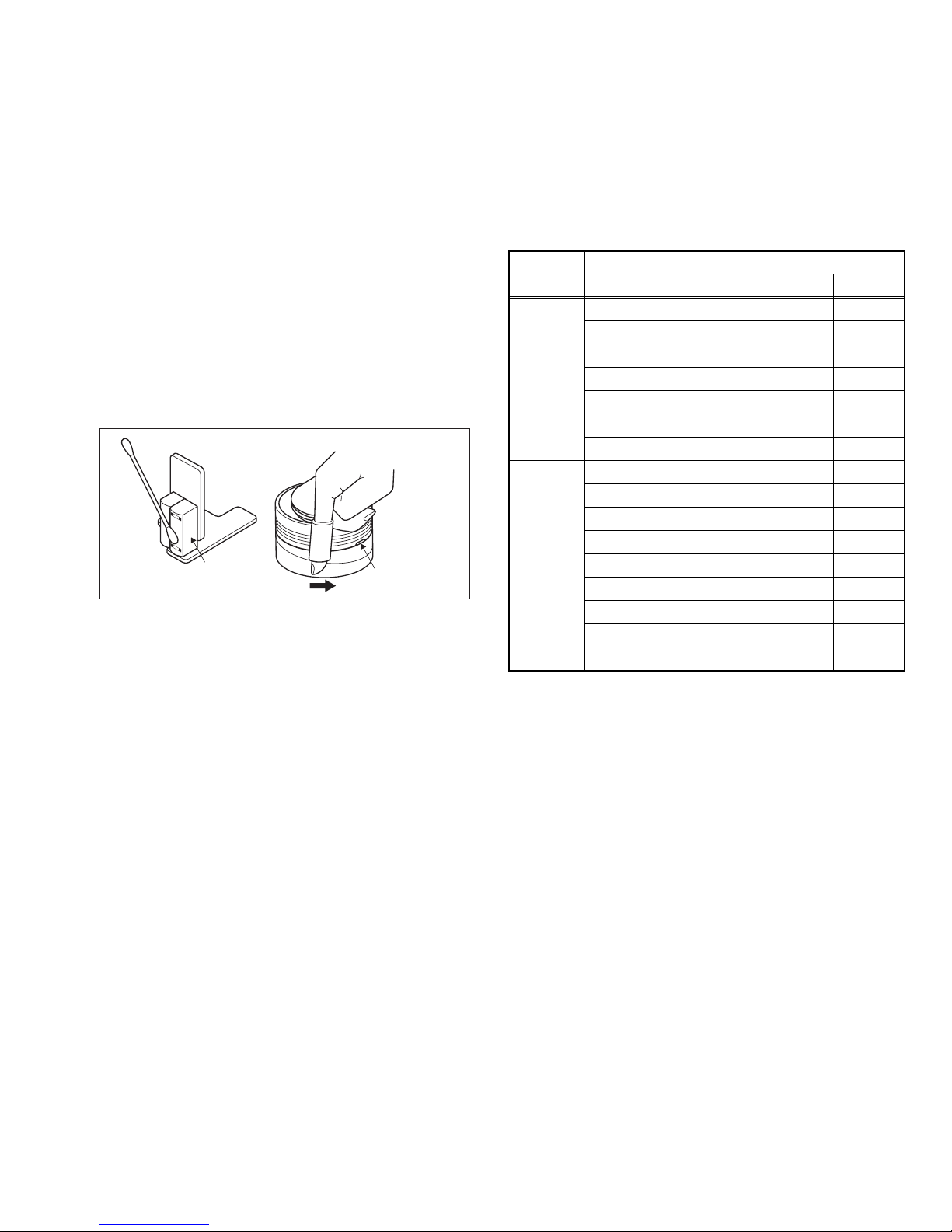
2.4.1 How to set the "Mechanism service mode"
(1) Set the VCR to the Jig RCU mode (the mode in which
codes from the Jig RCU can be received).
(2) Transmit the code "E5" from the Jig RCU.
(3) Release the lug of the Cassette holder and then slide the
Cassette holder toward the direction where the Cassette
holder is loaded by manually.
(4) The cassette holder lowers and, when the loading has
completed, the mechanism enters the desired mode.
When the VCR is set to the Mechanism service mode, the
symbols ("Timer") in the FDP (LED) are blinked.
2.4.2 How to exit from the "Mechanism service mode"
(1) Unplug the power cord plug from the power outlet.
Main board
assembly
TP2253
A.PB.FM
TP106
PB.FM
TP2254
A.REC.FM
C3025
TIMER
CLOCK
TP4001
CTL.P
TP111
D.FF
User RCU mode
( :not displayed)
Jig RCU mode