Hard Disk Drive (HDD)
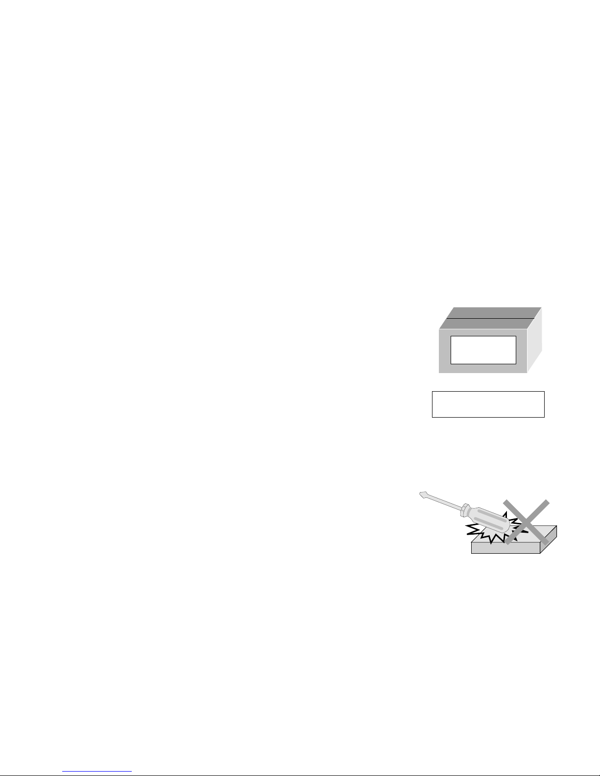
Important Safety Precautions
INSTRUCTIONS
1. DISASSEMBLY
1.1 HOW TO REMOVE THE MAJOR PARTS ..................................................... 1-1
1.1.1 Introduction .................................................................................... 1-1
1.2 HOW TO READ THE DISASSEMBLY AND ASSEMBLY .............................. 1-1
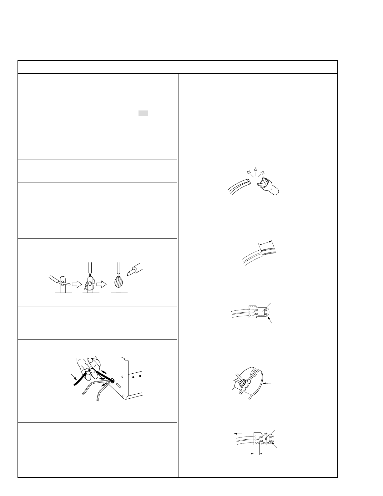
1.3 DISCONNECTION OF CONNECTORS (WIRES) ........................................ 1-1
1.4 SCREWS USED CABINET COMPONENTS AND BOARD ASSEMBLIES .. 1-1
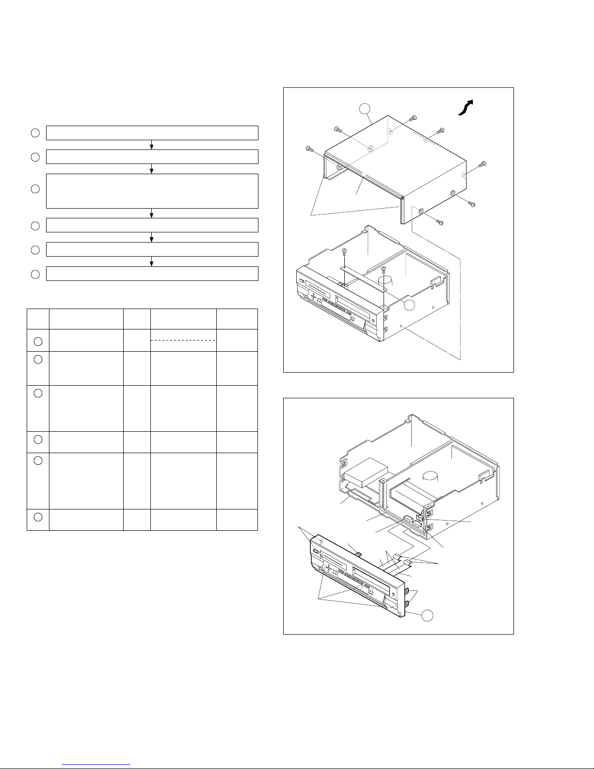
1.5 HOW TO REMOVE THE MAJOR PARTS <COM section> ........................... 1-2
1.5.1 Disassembly flow chart .................................................................. 1-2
1.5.2 Disassembly/assembly method <COM section> ............................ 1-2
1.6 HOW TO REMOVE THE MAJOR PARTS <VHS section> ............................ 1-4
1.6.1 Disassembly flow chart .................................................................. 1-4
1.6.2 DIsassembly/assembly method <VHS section> ............................ 1-4
Hard Disk Drive (HDD) Handling Precautions ...................................................... 1-6
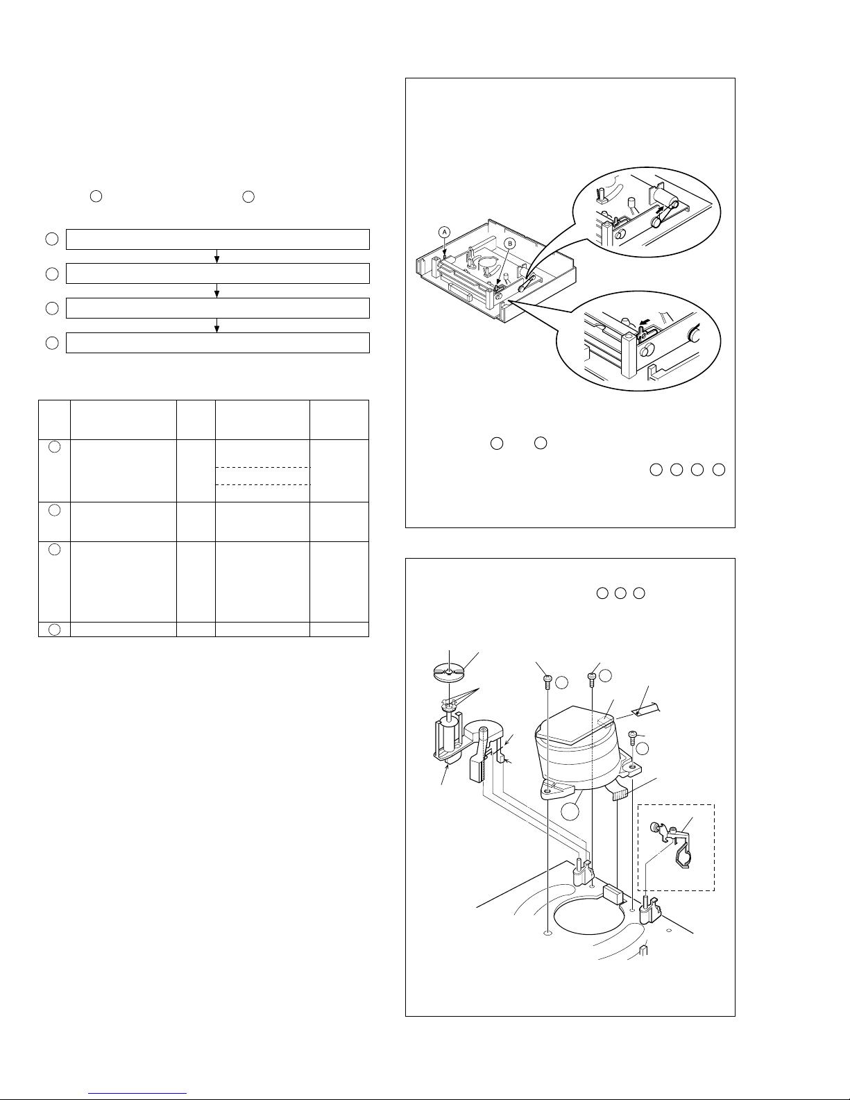
1.7 HOW TO REMOVE THE MAJOR PARTS <HDD section> ............................ 1-6
1.7.1 Disassembly flow chart .................................................................. 1-6
1.7.2 DIsassembly/assembly method <HDD section> ............................ 1-6
1.8 SERVICE POSITIONS .................................................................................. 1-7
1.8.1 Service position <VHS SIDE> ........................................................ 1-7
1.8.2 Service position <HDD SIDE> ....................................................... 1-8
1.9 MECHANISM SERVICE MODE .................................................................... 1-9
1.9.1 How to set the "MECHANISM SERVICE MODE" .......................... 1-9
1.10 CONNECTION ........................................................................................... 1-10
1.11 EMERGENCY DISPLAY FUNCTION ........................................................ 1-12
1.11.1 Displaying the emergency information ................................................. 1-12
1.11.2 Clearing the emergency history ........................................................... 1-12
1.11.3 Emergency content description ............................................................ 1-13
1.11.4 Emergency detail information 1......................................................... 1-14
1.11.5 Emergency detail information 2......................................................... 1-15
2. MECHANISM ADJUSTMENT (VHS)
2.1 Before starting repair and adjustment ............................................................ 2-1
2.1.1 Precautions .................................................................................... 2-1
2.1.2 Checking for proper mechanical operations ................................... 2-1
2.1.3 Manually removing the cassette tape ............................................. 2-1
2.1.4 Jigs and tools required for adjustment ........................................... 2-2
2.1.5 Maintenance and inspection .......................................................... 2-3
2.2 Replacement of major parts .......................................................................... 2-6
2.2.1
Before starting disassembling (Phase matching between mechanical parts) ..
2-6
2.2.2 How to set the “Mechanism assembling mode” ............................. 2-6
2.2.3 Cassette holder assembly .............................................................. 2-6
2.2.4 Pinch roller arm assembly .............................................................. 2-8
2.2.5 Guide arm assembly and press lever assembly ............................. 2-8
2.2.6 A/C head ........................................................................................ 2-8
2.2.7 Loading motor ................................................................................ 2-8
2.2.8 Capstan motor ................................................................................ 2-9
2.2.9 Pole base assembly (supply or take-up side) ................................. 2-9
2.2.10 Rotary encoder ............................................................................ 2-10
2.2.11 Clutch unit .................................................................................... 2-10
2.2.12
Change lever assembly, direct gear, clutch gear and coupling gear .
2-10
2.2.13 Link lever ...................................................................................... 2-11
2.2.14 Cassette gear, control cam and worm gear ................................. 2-11
2.2.15 Control plate ................................................................................. 2-11
2.2.16
Loading arm gear (supply or take-up side) and loading arm gear shaft ..
2-12
2.2.17 Take-up lever, take-up head and control plate guide .................... 2-13
2.2.18 Capstan brake assembly .............................................................. 2-13
2.2.19 Sub brake assembly (take-up side) .............................................. 2-13
2.2.20 Main brake assembly (take-up side), reel disk (take-up side) and
main brake assembly (supply side) .............................................. 2-13
2.2.21
Tension brake assembly, reel disk (supply side) and tension arm assembly .
2-14
2.2.22 Idler lever, idler arm assembly ..................................................... 2-14
2.2.23 Stator assembly ........................................................................... 2-14
2.2.24 Rotor assembly ............................................................................ 2-14
2.2.25 Upper drum assembly .................................................................. 2-15
2.3 Compatibility adjustment ............................................................................. 2-16
2.3.1 FM waveform linearity .................................................................. 2-16
2.3.2 Height and tilt of the A/C head ..................................................... 2-17
2.3.3 A/C head phase (X-value) ............................................................ 2-17
2.3.4 Standard tracking preset .............................................................. 2-18
2.3.5 Tension pole position .................................................................... 2-18
3. ELECTRICAL ADJUSTMENT (VHS)
3.1 PRECAUTION ............................................................................................... 3-1
3.1.1 Required test equipments .............................................................. 3-1
3.1.2 Required adjustment tools ............................................................. 3-1
3.1.3 Color (colour) bar signal,Color (colour) bar pattern ....................... 3-1
3.1.4 Switch settings and standard precautions ...................................... 3-1
3.1.5 EVR Adjustment ............................................................................. 3-1
TABLE OF CONTENTS
Section Title Page Section Title Page
3.2 SERVO CIRCUIT .......................................................................................... 3-2
3.2.1 Switching point ............................................................................... 3-2
3.2.2 Slow tracking preset ....................................................................... 3-2
3.3 VIDEO CIRCUIT ........................................................................................... 3-2
3.3.1 D/A level ......................................................................................... 3-2
3.3.2 EE Y level ....................................................................................... 3-3
3.3.3 PB Y level (S-VHS / VHS) .............................................................. 3-3
3.3.4 REC color (colour) level ................................................................. 3-3
3.3.5 Video EQ (Frequency response) .................................................... 3-4
3.3.6 AUTO PICTURE initial setting ........................................................ 3-4
3.4 DIGITAL CIRCUIT ......................................................................................... 3-4
3.4.1 HDD EE Y level .............................................................................. 3-4
3.4.2 HDD PB Y level .............................................................................. 3-5
3.4.3 HDD PB C burst level ..................................................................... 3-5
3.5 AUDIO CIRCUIT ........................................................................................... 3-5
3.5.1 Audio REC FM ............................................................................... 3-5
3.6 SYSCON CIRCUIT [HM-HDS1EU] ............................................................... 3-6
3.6.1 Timer clock ..................................................................................... 3-6
4. CHARTS AND DIAGRAMS
NOTES OF SCHEMATIC DIAGRAM ................................................................... 4-1
CIRCUIT BOARD NOTES .................................................................................... 4-2
4.1 BOARD INTERCONNECTIONS ................................................................... 4-3
4.2
SWITCHING REGULATOR AND REGULATOR SCHEMATIC DIAGRAMS ...........
4-5
4.3 VIDEO/AUDIO SCHEMATIC DIAGRAM ....................................................... 4-7
4.4 SYSTEM CONTROL SCHEMATIC DIAGRAM ............................................. 4-9
4.5 VIDEO I/O SWITCH SCHEMATIC DIAGRAM ............................................ 4-13
4.6 AUDIO I/O SCHEMATIC DIAGRAM ............................................................ 4-15
4.7 CONNECTION SCHEMATIC DIAGRAM .................................................... 4-17
4.8 TUNER SCHEMATIC DIAGRAM ................................................................ 4-19
4.9 3D DIGITAL/2M SCHEMATIC DIAGRAM ................................................... 4-21
4.10 TERMINAL SCHEMATIC DIAGRAM ........................................................ 4-23
4.11 DEMODULATOR SCHEMATIC DIAGRAM ............................................... 4-25
4.12 S-SUB SCHEMATIC DIAGRAM ............................................................... 4-27
4.13 ON SCREEN SCHEMATIC DIAGRAM ..................................................... 4-29
4.14
EJECT SW, DISPLAY, JACK, LED/SW AND LED SCHEMATIC DIAGRAMS ..
4-31
4.15 DIGITAL P.SUP SCHEMATIC DIAGRAM .................................................. 4-33
4.16 DIGITAL VIDEO SCHEMATIC DIAGRAM ................................................. 4-35
4.17 DIGITAL AUDIO SCHEMATIC DIAGRAM ................................................ 4-37
4.18 DIGITAL MPEG DEC SCHEMATIC DIAGRAM ......................................... 4-39
4.19 DIGITAL MPEG ENC SCHEMATIC DIAGRAM ......................................... 4-41
4.20 DIGITAL ASIC IF SCHEMATIC DIAGRAM ............................................... 4-43
4.21 SWITCHING REGULATOR AND REGULATOR CIRCUIT BOARDS ....... 4-45
4.22 3D DIGITAL/2M AND S-SUB CIRCUIT BOARDS .................................... 4-47
4.23 TERMINAL CIRCUIT BOARD .................................................................. 4-48
4.24 EJECT SW, DISPLAY, JACK, LED/SW, AND LED CIRCUIT BOARDS .... 4-49
4.25 MAIN CIRCUIT BOARD ........................................................................... 4-51
4.26 DEMODULATOR AND ON SCREEN CIRCUIT BOARDS ........................ 4-54
4.27 DIGITAL CIRCUIT BOARD ....................................................................... 4-55
4.28 FDP GRID ASSIGNMENT AND ANODE CONNECTION ........................ 4-58
4.29 DIGITAL SUB SCHEMATIC DIAGRAM .................................................... 4-59
4.30 DIGITAL SUB CIRCUIT BOARD .............................................................. 4-61
4.31 REMOTE CONTROL SCHEMATIC DIAGRAM ........................................ 4-62
4.32 WAVEFORMS ........................................................................................... 4-63
4.33 VOLTAGE CHARTS .................................................................................. 4-65
4.34 CPU PIN FUNCTION ................................................................................ 4-68
4.35 SYSTEM CONTROL BLOCK DIAGRAM (VHS) ....................................... 4-69
4.36 AUDIO BLOCK DIAGRAM ........................................................................ 4-71
4.37 VIDEO BLOCK DIAGRAM(VHS) .............................................................. 4-73
4.38 VIDEO/AUDIO BLOCK DIAGRAM (HDD) ................................................ 4-77
5. PARTS LIST
5.1 PACKING AND ACCESSORY ASSEMBLY <M1> ....................................... 5-1
5.2 FINAL ASSEMBLY <M2> ............................................................................. 5-2
5.3 MECHANISM ASSEMBLY <M4> .................................................................. 5-4
5.4 ELECTRICAL PARTS LIST ........................................................................... 5-6
SW.REG BOARD ASSEMBLY <01> ......................................................... 5-6
REG BOARD ASSEMBLY <02> ............................................................... 5-7
MAIN BOARD ASSEMBLY <03> .............................................................. 5-8
3D DIGITAL/2M BOARD ASSEMBLY <05> ............................................ 5-15
TERMINAL BOARD ASSEMBLY <06> ................................................... 5-17
A/C HEAD BOARD ASSEMBLY <12> .................................................... 5-18
DEMOD BOARD ASSEMBLY <14> ........................................................ 5-18
S-SUB BOARD ASSEMBLY <15> .......................................................... 5-19
ON SCREEN BOARD ASSEMBLY <17> ................................................ 5-20
EJECT SW BOARD ASSEMBLY <27> ................................................... 5-20
SW/DISPLAY BOARD ASSEMBLY <28> ................................................ 5-20
JACK BOARD ASSEMBLY <36> ............................................................ 5-21
LED/SW BOARD ASSEMBLY <47> ....................................................... 5-22
DIGITAL SUB BOARD ASSEMBLY <49> ............................................... 5-22
DIGITAL BOARD ASSEMBLY <50> ........................................................ 5-22
LOADING MOTOR BOARD ASSEMBLY <55> ....................................... 5-27
LED BOARD ASSEMBLY <90> .............................................................. 5-27
HM-HDS1EK HM-HDS1EU
VIDEO SYSTEM PAL/NTSC ON PAL TV PAL/MESECAM(MANUAL)/NTSC ON PAL TV
BROADCASTING STANDARD I B/G,D/K
STEREO DECODER NICAM NICAM/A2
VCR PLUS+ VIDEOPLUS+ DELUXE SHOWVIEW DELUXE
VPS(AUTO) NOT USED USED
INITIAL (TIMER) OFF GER,AUS,SWISS:ON, OTHER:OFF
LANGUAGE [INITIAL] (ON SCREEN DISPLAY)
ENG 10 LANG. [E]
POWER PLUG 3PIN CEE
The following table lists the differing points between Models ( HM-HDS1EK and HM-HDS1EU) in this series.