JVC HM-DH40000K User manual

SERVICE MANUAL
COPYRIGHT © 2003 VICTOR COMPANY OF JAPAN, LIMITED No.82988
2003/8
D-VHS DIGITAL RECORDER
8298820038HM-DH40000K
Regading service information other than these sections, refer to the service manual No. 82933 (HM-DH40000U).
Also, be sure to note important safety precautions provided in the service manual.
SPECIFICATION
START STOP DATE
PLAY
REW
REC
STOP
PAUSE
FF
TV/VCR CH
C. RESET
CANCEL
DBS DAILY
WEEKLY
ENTER
REC
LINK
REC
SPEED
SKIP
SEARCH
MENU
NAVI
SUBTITLE
VCR
PROGRAM PROG.CHECK TIMER
A/B/C/D
TV
TV/VCR
CABLE
/DBS
POWER
REMOTE
CODE
., ? ABC DEF
GHI JKL MNO
PQRS TUV WXYZ
AUX
TV
VOL
A
.
M
O
N
I
TO
R
D
I
S
PL
A
Y
OSD
ENTER
B
AC
K
K
MTP
NTSC
HM-DH40000K D2D4

(No.82988)
AV & MULTIMEDIA COMPANY VIDEO RECORDER CATEGORY 12, 3-chome, Moriya-cho, kanagawa-ku, Yokohama, kanagawa-prefecture, 221-8528, Japan
VICTOR COMPANY OF JAPAN, LIMITED
WPC
Printed in Japan
DIFFERENCE LIST
DIFFERENT TABLE OF FEATURE
The following table indicates main different points between models HM-DH40000U and HM-DH40000K
DIFFERENT TABLE OF PARTS LIST
The following table indicate different parts number between models HM-DH40000U and HM-DH40000K.
PACKING AND ACCESSORY ASSEMBLY<M1>
FINAL ASSEMBLY<M2>
DIGITAL BOARD ASSEMBLY<50>
TERMINAL SUB BOARD ASSEMBLY<52>
Note :
Mark - is not used.
Mark * reference model was also changed.
Mark ←is same as left.
ITEM HM-DH40000U HM-DH40000K
POWER VOLTAGE 120V / 60Hz 110V / 60Hz
D-VHS CLEANING TAPE PROVIDED OPTIONAL
INSTRUCTION / LANGUAGE ENGLISH, FRENCH KOREAN
D THEATER REGION 1 REGION 3
VCR PLUS+ VCR+ C3 NOT USED
CABLE BOX or DBS.BOX CTL USED NOT USED
TITLE DOWNLOAD USED NOT USED
REF NO. ITEM HM-DH40000U HM-DH40000K
301 PACKING CASE LP31128-001B LP31128-014A
310 INST.BOOK(ENGLISH) LPT0698-001B -
310 INST.BOOK(FRENCH) LPT0698-002B -
310 INST.BOOK(KOREAN) - LPT0859-001A
315 LED CABLE ASSY QAL0095-004 -
318 REGIST.CARD BT-51028-2 -
320 CLEANING TAPE QAM0492-001 -
321 WARRANTY CARD - BT-56013-1
REF NO. ITEM HM-DH40000U HM-DH40000K
501 FRONT PANEL ASSY LP10437-001D LP10437-007A
510 TOP COVER PQ11922-52-13 *PQ11922-66
513 STICKER(TOP) LP31153-001A -
REF NO. ITEM HM-DH40000U HM-DH40000K
PW1 DIGITAL BOARD ASSY LPA10175-01D or LPA10175-01E LPA10175-05A
IC901 IC PDI1394P23BD or TSB41AB2PAP TSB41AB2PAP
C908 C CAPACITOR NOT USED or NCB31CK-104X NCB31CK-104X
REF NO. ITEM HM-DH40000U HM-DH40000K
PW1 TERMINAL SUB BOARD ASSY LPA10176-01A4 LPA10176-04A4
TB1 TERMINAL BOARD ASSY LP31132-001B LP31132-004A

SERVICE MANUAL
COPYRIGHT © 2003 VICTOR COMPANY OF JAPAN, LTD. No.82933
2003/06
D-VHS DIGITAL RECORDER
82933200306 HM-DH40000U
SPECIFICATION
GENERAL
VIDEO/AUDIO (D-VHS)
VIDEO/AUDIO (S-VHS/VHS)
TUNER
TIMER
CONNECTOR
ACCESSORIES
START STOP DATE
PLAY
REW
REC
STOP
PAUSE
FF
TV/VCR CH
C. RESET
CANCEL
DBS DAILY
WEEKLY
ENTER
REC
LINK
REC
SPEED
SKIP
SEARCH
MENU
NAVI
SUBTITLE
VCR
PROGRAM PROG.CHECK TIMER
A/B/C/D
TV
TV/VCR
CABLE
/DBS
POWER
REMOTE
CODE
. , ? ABC DEF
GHI JKL MNO
PQRS TUV WXYZ
AUX
TV
VOL
A
.
M
O
N
I
TO
R
D
I
S
PL
A
Y
OSD
ENTE
R
B
AC
K
K
MTP
NTSC
Power requirement AC 120 V~, 60 Hz
Power consumption
Power on 42 W
Power off 18 W
Temperature Operating 5°C to 40°C (41°F to 104°F)
Storage -20°C to 60°C (-4°F to 140°F)
Operating position Horizontal only
Dimensions (W x H x D) 435 mm x 94 mm x 383 mm
(17-3/16" x 3-3/4" x 15-1/8")
Weight 5.5 kg (12.2 lbs)
Maximum recording time
D-VHS (HS) 210 min. with DF-420 video cassette
D-VHS (STD) 420 min. with DF-420 video cassette
D-VHS (LS3) 1260 min. with DF-420 video cassette
D-VHS (LS5) 2100 min. with DF-420 video cassette
S-VHS/VHS (SP) 210 min. with ST-210 video cassette
S-VHS/VHS (EP) 630 min. with ST-210 video cassette
Video format MPEG2 standard
Audio format Encode MPEG1 Layer2
Decode MPEG1 Layer2/Dolby Digital
LINEAR PCM (HS/STD)
Track composition
Tape speed 33.4 mm/sec (HS mode)
16.67 mm/sec (STD mode)
5.55 mm/sec (LS3 mode)
3.33 mm/sec (LS5 mode)
Head azimuth ±30 deg
Drum rotation 1800 rpm
Tracking system CTL track system
Recording specification
Main data input rate 28.2 Mbps (HS mode)
14.1 Mbps (STD mode)
4.7 Mbps (LS3 mode)
2.8 Mbps (LS5 mode)
Interface IEEE1394 compliant DTCP digital copy
protection compatible
Format S-VHS/VHS NTSC standard
Signal system NTSC-type color signal and
EIA monochrome signal, 525 lines/60 fields
Recording/Playback
system DA-4 (Double Azimuth) head helical scan
system
Signal-to-noise ratio 45 dB
Frequency range
Normal audio 70 Hz to 10,000 Hz
Hi-Fi audio 20 Hz to 20,000 Hz
Tuning system Frequency-synthesized tuner
Channel coverage VHF Channels 2-13
UHF Channels 14-69
CATV 113 Channels
Clock reference Quartz
Program capacity 1-year programmable timer/24 programs
Memory backup time Approx. 10 min.
Input/Output i.LINK IN/OUT (DV IN) x 2 (4-pin, S400)
RCA connectors (IN x 3, OUT x 2)
S-video connectors (IN x 3, OUT x 2)
Component video OUT (Y, PB/CB, PR/CR) x 1
Digital OUT (optical) x 1
Provided accessories Infrared remote control unit, “AA” battery x 2,
Audio cable, RF cable (F-type),
S-video cable (4-pin), Controller
D2D4

1-2 (No.82933)
TABLE OF CONTENTS
1 PRECAUTIONS . . . . . . . . . . . . . . . . . . . . . . . . . . . . . . . . . . . . . . . . . . . . . . . . . . . . . . . . . . . . . . . . . . . . . . . .1-3
1.1 SAFTY PRECAUTIONS . . . . . . . . . . . . . . . . . . . . . . . . . . . . . . . . . . . . . . . . . . . . . . . . . . . . . . . . . . . .1-3
2 SPECIFIC SERVICE INSTRUCTIONS . . . . . . . . . . . . . . . . . . . . . . . . . . . . . . . . . . . . . . . . . . . . . . . . . . . . . .1-5
2.1 Disassembly flow chart . . . . . . . . . . . . . . . . . . . . . . . . . . . . . . . . . . . . . . . . . . . . . . . . . . . . . . . . . . . . .1-5
2.2 How to read the disassembly and assembly. . . . . . . . . . . . . . . . . . . . . . . . . . . . . . . . . . . . . . . . . . . . .1-5
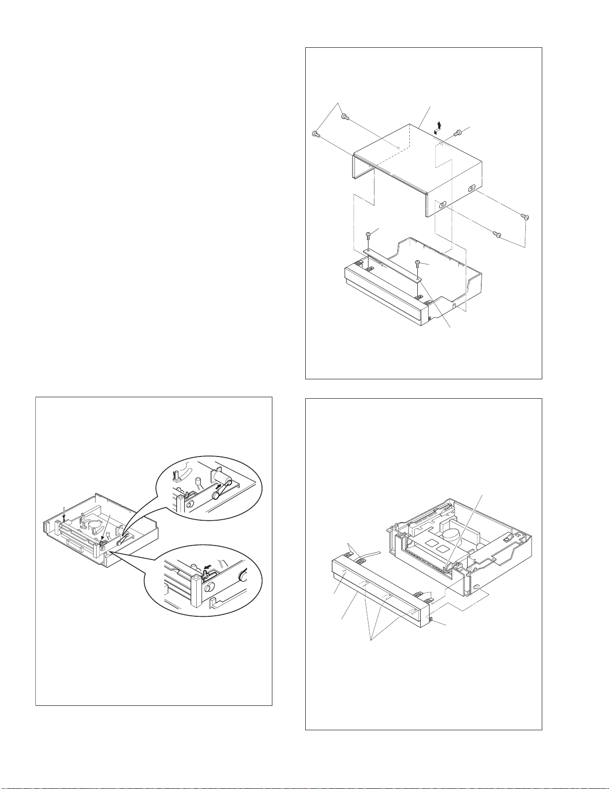
2.3 Disassembly/assembly method. . . . . . . . . . . . . . . . . . . . . . . . . . . . . . . . . . . . . . . . . . . . . . . . . . . . . . .1-5
2.4 Service position. . . . . . . . . . . . . . . . . . . . . . . . . . . . . . . . . . . . . . . . . . . . . . . . . . . . . . . . . . . . . . . . . . .1-9
2.5 Mechanism service mode . . . . . . . . . . . . . . . . . . . . . . . . . . . . . . . . . . . . . . . . . . . . . . . . . . . . . . . . . .1-10
2.6 Jig RCU mode. . . . . . . . . . . . . . . . . . . . . . . . . . . . . . . . . . . . . . . . . . . . . . . . . . . . . . . . . . . . . . . . . . .1-10
2.7 Opening on the chassis. . . . . . . . . . . . . . . . . . . . . . . . . . . . . . . . . . . . . . . . . . . . . . . . . . . . . . . . . . . .1-10
2.8 Emergency display function . . . . . . . . . . . . . . . . . . . . . . . . . . . . . . . . . . . . . . . . . . . . . . . . . . . . . . . .1-11
3 MECHANISM ADJUSTMENT . . . . . . . . . . . . . . . . . . . . . . . . . . . . . . . . . . . . . . . . . . . . . . . . . . . . . . . . . . . .1-15
3.1 Before starting repair and adjustment . . . . . . . . . . . . . . . . . . . . . . . . . . . . . . . . . . . . . . . . . . . . . . . . .1-15
3.2 Replacement of major parts . . . . . . . . . . . . . . . . . . . . . . . . . . . . . . . . . . . . . . . . . . . . . . . . . . . . . . . .1-19
3.3 Compatibility adjustment. . . . . . . . . . . . . . . . . . . . . . . . . . . . . . . . . . . . . . . . . . . . . . . . . . . . . . . . . . .1-28
4 ELECTRICAL ADJUSTMENT . . . . . . . . . . . . . . . . . . . . . . . . . . . . . . . . . . . . . . . . . . . . . . . . . . . . . . . . . . . .1-31
4.1 Precaution. . . . . . . . . . . . . . . . . . . . . . . . . . . . . . . . . . . . . . . . . . . . . . . . . . . . . . . . . . . . . . . . . . . . . .1-31
4.2 Servo circuit. . . . . . . . . . . . . . . . . . . . . . . . . . . . . . . . . . . . . . . . . . . . . . . . . . . . . . . . . . . . . . . . . . . . .1-32
4.3 Audio circuit. . . . . . . . . . . . . . . . . . . . . . . . . . . . . . . . . . . . . . . . . . . . . . . . . . . . . . . . . . . . . . . . . . . . .1-34
4.4 Digital circuit . . . . . . . . . . . . . . . . . . . . . . . . . . . . . . . . . . . . . . . . . . . . . . . . . . . . . . . . . . . . . . . . . . . .1-34
CHARTS AND DIAGRAMS
BOARD INTERCONNECTIONS. . . . . . . . . . . . . . . . . . . . . . . . . . . . . . . . . . . . . . . . . . . . . . . . . . . . . .2-3
SW.REG AND MAIN (REG) SCHEMATIC DIAGRAMS . . . . . . . . . . . . . . . . . . . . . . . . . . . . . . . . . . . .2-5
MAIN (VIDEO/AUDIO) SCHEMATIC DIAGRAM. . . . . . . . . . . . . . . . . . . . . . . . . . . . . . . . . . . . . . . . . .2-7
MAIN (SYNC DET) SCHEMATIC DIAGRAM . . . . . . . . . . . . . . . . . . . . . . . . . . . . . . . . . . . . . . . . . . . .2-9
MAIN (S-SUB) SCHEMATIC DIAGRAM. . . . . . . . . . . . . . . . . . . . . . . . . . . . . . . . . . . . . . . . . . . . . . .2-11
MAIN (FMA/DEMOD) SCHEMATIC DIAGRAM . . . . . . . . . . . . . . . . . . . . . . . . . . . . . . . . . . . . . . . . .2-13
MAIN (SYSCON) SCHEMATIC DIAGRAM. . . . . . . . . . . . . . . . . . . . . . . . . . . . . . . . . . . . . . . . . . . . .2-15
MAIN (TUNER) SCHEMATIC DIAGRAM . . . . . . . . . . . . . . . . . . . . . . . . . . . . . . . . . . . . . . . . . . . . . .2-17
MAIN (TERMINAL) AND TERMINAL SUB SCHEMATIC DIAGRAMS. . . . . . . . . . . . . . . . . . . . . . . .2-19
RESET SW,REC SAFETY/D.CASS SW,DISPLAY AND JACK SCHEMATIC DIAGRAMS . . . . . . . .2-21
PRE/REC SCHEMATIC DIAGRAM. . . . . . . . . . . . . . . . . . . . . . . . . . . . . . . . . . . . . . . . . . . . . . . . . . .2-23
DIGITAL(SUB CPU) SCHEMATIC DIAGRAM . . . . . . . . . . . . . . . . . . . . . . . . . . . . . . . . . . . . . . . . . .2-25
DIGITAL(DMAIN) SCHEMATIC DIAGRAM. . . . . . . . . . . . . . . . . . . . . . . . . . . . . . . . . . . . . . . . . . . . .2-27
DIGITAL(DMAIN IF) SCHEMATIC DIAGRAM . . . . . . . . . . . . . . . . . . . . . . . . . . . . . . . . . . . . . . . . . .2-29
DIGITAL(E5) SCHEMATIC DIAGRAM . . . . . . . . . . . . . . . . . . . . . . . . . . . . . . . . . . . . . . . . . . . . . . . .2-31
DIGITAL(E5 DDR) SCHEMATIC DIAGRAM. . . . . . . . . . . . . . . . . . . . . . . . . . . . . . . . . . . . . . . . . . . .2-33
DIGITAL(MEMORY) SCHEMATIC DIAGRAM . . . . . . . . . . . . . . . . . . . . . . . . . . . . . . . . . . . . . . . . . .2-35
DIGITAL(DIGITAL IF) SCHEMATIC DIAGRAM . . . . . . . . . . . . . . . . . . . . . . . . . . . . . . . . . . . . . . . . .2-37
DIGITAL(VIDEO) SCHEMATIC DIAGRAM. . . . . . . . . . . . . . . . . . . . . . . . . . . . . . . . . . . . . . . . . . . . .2-39
DIGITAL(AUDIO) SCHEMATIC DIAGRAM. . . . . . . . . . . . . . . . . . . . . . . . . . . . . . . . . . . . . . . . . . . . .2-41
SW.REG, DISPLAY, REC SAFETY, JACK AND TERMINAL SUB CIRCUIT BOARDS. . . . . . . . . . .2-43
MAIN CIRCUIT BOARD . . . . . . . . . . . . . . . . . . . . . . . . . . . . . . . . . . . . . . . . . . . . . . . . . . . . . . . . . . .2-45
COMPONENT PARTS LOCATION GUIDE <MAIN> LPB10177-001C. . . . . . . . . . . . . . . . . . . . . . . .2-47
PRE/REC CIRCUIT BOARD. . . . . . . . . . . . . . . . . . . . . . . . . . . . . . . . . . . . . . . . . . . . . . . . . . . . . . . .2-48
COMPONENT PARTS LOCATION GUIDE <PRE/REC> LPB10174-001B . . . . . . . . . . . . . . . . . . . .2-48
DIGITAL CIRCUIT BOARD. . . . . . . . . . . . . . . . . . . . . . . . . . . . . . . . . . . . . . . . . . . . . . . . . . . . . . . . .2-49
COMPONENT PARTS LOCATION GUIDE <DIGITAL> LPB10175-001B . . . . . . . . . . . . . . . . . . . . .2-51
REMOTE CONTROLLER SCHEMATIC DIAGRAM . . . . . . . . . . . . . . . . . . . . . . . . . . . . . . . . . . . . . 2-53
FDP GRID ASSIGNMENT AND ANODE CONNECTION. . . . . . . . . . . . . . . . . . . . . . . . . . . . . . . . . .2-53
CPU PIN FUNCTION . . . . . . . . . . . . . . . . . . . . . . . . . . . . . . . . . . . . . . . . . . . . . . . . . . . . . . . . . . . . .2-54
VOLTAGE CHARTS . . . . . . . . . . . . . . . . . . . . . . . . . . . . . . . . . . . . . . . . . . . . . . . . . . . . . . . . . . . . . .2-55
WAVEFORMS. . . . . . . . . . . . . . . . . . . . . . . . . . . . . . . . . . . . . . . . . . . . . . . . . . . . . . . . . . . . . . . . . . .2-56
VIDEO BLOCK DIAGRAM (1). . . . . . . . . . . . . . . . . . . . . . . . . . . . . . . . . . . . . . . . . . . . . . . . . . . . . . .2-57
VIDEO BLOCK DIAGRAM (2). . . . . . . . . . . . . . . . . . . . . . . . . . . . . . . . . . . . . . . . . . . . . . . . . . . . . . .2-59
AUDIO BLOCK DIAGRAM . . . . . . . . . . . . . . . . . . . . . . . . . . . . . . . . . . . . . . . . . . . . . . . . . . . . . . . . .2-61
SYSTEM CONTROL BLOCK DIAGRAM . . . . . . . . . . . . . . . . . . . . . . . . . . . . . . . . . . . . . . . . . . . . . .2-63
D-VHS BLOCK DIAGRAM . . . . . . . . . . . . . . . . . . . . . . . . . . . . . . . . . . . . . . . . . . . . . . . . . . . . . . . . .2-65
PARTS LIST
1. EXPLODED VIEW
1.1 PACKING AND ACCESORY ASSEMBLY<M1> . . . . . . . . . . . . . . . . . . . . . . . . . . . . . . . . . . . . .3-1
1.2 FINAL ASSEMBLY<M2>. . . . . . . . . . . . . . . . . . . . . . . . . . . . . . . . . . . . . . . . . . . . . . . . . . . . . . .3-2
1.3 MECHANISM ASSEMBLY<M4> . . . . . . . . . . . . . . . . . . . . . . . . . . . . . . . . . . . . . . . . . . . . . . . . .3-4
2. PARTS LIST
SWITCHING REGULATOR BOARD ASSEMBLY<01>. . . . . . . . . . . . . . . . . . . . . . . . . . . . . . . . . . .3-6
MAIN BOARD ASSEMBLY<01> . . . . . . . . . . . . . . . . . . . . . . . . . . . . . . . . . . . . . . . . . . . . . . . . . . . .3-7
A/C HEAD BOARD ASSEMBLY<12> . . . . . . . . . . . . . . . . . . . . . . . . . . . . . . . . . . . . . . . . . . . . . . .3-13
DISPLAY BOARD ASSEMBLY<28> . . . . . . . . . . . . . . . . . . . . . . . . . . . . . . . . . . . . . . . . . . . . . . . .3-13
REC SAFETY BOARD ASSEMBLY<32> . . . . . . . . . . . . . . . . . . . . . . . . . . . . . . . . . . . . . . . . . . . .3-13
JACK BOARD ASSEMBLY<36> . . . . . . . . . . . . . . . . . . . . . . . . . . . . . . . . . . . . . . . . . . . . . . . . . . .3-14
PRE/REC BOARD ASSEMBLY<43>. . . . . . . . . . . . . . . . . . . . . . . . . . . . . . . . . . . . . . . . . . . . . . . .3-14
DIGITAL BOARD ASSEMBLY<50>. . . . . . . . . . . . . . . . . . . . . . . . . . . . . . . . . . . . . . . . . . . . . . . . .3-16
TERMINAL SUB BOARD ASSEMBLY<52> . . . . . . . . . . . . . . . . . . . . . . . . . . . . . . . . . . . . . . . . . .3-24
LOADING MOTOR BOARD ASSEMBLY<55> . . . . . . . . . . . . . . . . . . . . . . . . . . . . . . . . . . . . . . . .3-24

(No.82933)1-3
SECTION 1
PRECAUTIONS
1.1 SAFTY PRECAUTIONS
Prior to shipment from the factory, JVC products are strictly in-
spected to conform with the recognized product safety and elec-
trical codes of the countries in which they are to be
sold.However,in order to maintain such compliance, it is equally
important to implement the following precautions when a set is
being serviced.
1.1.1 Precautions during Servicing
(1) Locations requiring special caution are denoted by labels
and inscriptions on the cabinet, chassis and certain parts of
the product.When performing service, be sure to read and
comply with these and other cautionary notices appearing in
the operation and service manuals.
(2) Parts identified by the symbol and shaded ( ) parts
are critical for safety.
Replace only with specified part numbers.
NOTE :
Parts in this category also include those specified to
comply with X-ray emission standards for products
using cathode ray tubes and those specified for com-
pliance with various regulations regarding spurious
radiation emission.
(3) Fuse replacement caution notice.
Caution for continued protection against fire hazard.
Replace only with same type and rated fuse(s) as specified.
(4) Use specified internal wiring. Note especially:
• Wires covered with PVC tubing
• Double insulated wires
• High voltage leads
(5) Use specified insulating materials for hazardous live parts.
Note especially:
• Insulation Tape
• PVC tubing
•Spacers
• Insulation sheets for transistors
• Barrier
(6) When replacing AC primary side components (transformers,
power cords, noise blocking capacitors, etc.) wrap ends of
wires securely about the terminals before soldering.
Fig.1-1-1
(7) Observe that wires do not contact heat producing parts
(heatsinks, oxide metal film resistors, fusible resistors, etc.)
(8) Check that replaced wires do not contact sharp edged or
pointed parts.
(9) When a power cord has been replaced, check that 10-15 kg
of force in any direction will not loosen it.
Fig.1-1-2
(10) Also check areas surrounding repaired locations.
(11) Products using cathode ray tubes (CRTs)In regard to such
products, the cathode ray tubes themselves, the high volt-
age circuits, and related circuits are specified for compliance
with recognized codes pertaining to X-ray emission. Conse-
quently, when servicing these products, replace the cathode
raytubesand otherpartswithonlythespecifiedparts.Under
no circumstances attempt to modify these circuits.Unautho-
rized modification can increase the high voltage value and
cause X-ray emission from the cathode ray tube.
(12) Crimp type wire connector
In such cases as when replacing the power transformer in
sets where the connections between the power cord and
power trans former primary lead wires are performed using
crimp type connectors, if replacing the connectors is un-
avoidable, in order to prevent safety hazards, perform care-
fully and precisely according to the following steps.
•Connector part number :E03830-001
•Required tool : Connector crimping tool of the proper
type which will not damage insulated parts.
•Replacement procedure
a) Remove the old connector by cutting the wires at a
point close to the connector.
Important : Do not reuse a connector (discard it).
Fig.1-1-3
b) Strip about 15 mm of the insulation from the ends of
the wires. If the wires are stranded, twist the strands
to avoid frayed conductors.
Fig.1-1-4
c) Align the lengths of thewires to be connected. Insert
the wires fully into the connector.
Fig.1-1-5
d) Asshown in Fig.1-1-6, use thecrimping tool tocrimp
the metal sleeve at the center position. Be sure to
crimp fully to the complete closure of the tool.
Fig.1-1-6
e) Check the four points noted in Fig.1-1-7.
Fig.1-1-7
Power cord
cut close to connector
15 mm
Connector
Metal sleeve
1.25
2.0
5.5
Crimping tool
Not easily pulled free Crimped at approx. cente
r
of metal sleev
e
Conductors extended
Wire insulation recessed
more than 4 mm

1-4 (No.82933)
1.1.2 Safety Check after Servicing
Examine the area surrounding the repaired location for damage
or deterioration. Observe that screws, parts and wires have been
returned to original positions, Afterwards, perform the following
tests and confirm the specified values in order to verify compli-
ance with safety standards.
(1) Insulation resistance test
Confirm the specified insulation resistance or greater be-
tween power cord plug prongs and externally exposed
parts of the set (RF terminals, antenna terminals, video and
audio input and output terminals, microphone jacks, ear-
phone jacks, etc.).
See table 1 below.
(2) Dielectric strength test
Confirm specified dielectric strength or greater between
power cord plug prongs and exposed accessible parts of
the set (RF terminals, antenna terminals, video and audio
input and output terminals, microphone jacks, earphone
jacks, etc.). See Fig.1-1-11 below.
(3) Clearance distance
When replacing primary circuit components, confirm spec-
ified clearance distance (d), (d') between soldered termi-
nals, and between terminals and surrounding metallic
parts. See Fig.1-1-11 below.
Fig.1-1-8
(4) Leakage current test
Confirm specified or lower leakage current between earth
ground/power cord plug prongs and externally exposed ac-
cessible parts (RF terminals, antenna terminals, video and
audio input and output terminals, microphone jacks, ear-
phone jacks, etc.).
Measuring Method : (Power ON)
Insert load Z between earth ground/power cord plug
prongs and externally exposed accessible parts. Use an
AC voltmeter to measure across both terminals of load Z.
See Fig.1-1-9 and following Fig.1-1-12.
Fig.1-1-9
(5) Grounding (Class 1 model only)
Confirm specified or lower grounding impedance between
earth pin in AC inlet and externally exposed accessible
parts (Video in, Video out, Audio in, Audio out or Fixing
screw etc.).
Measuring Method:
Connect milli ohm meter between earth pin in AC inlet and
exposed accessible parts. See Fig.1-1-10 and grounding
specifications.
Fig.1-1-10
Fig.1-1-11
Fig.1-1-12
NOTE :
These tables are unofficial and for reference only. Be sure to confirm the precise values for your particular country and locality.
ab
c
VA
Externally
exposed
accessible part
Z

(No.82933)1-5
SECTION 2
SPECIFIC SERVICE INSTRUCTIONS
2.1 Disassembly flow chart
This flowchart lists the disassembling steps for the cabinet parts
and P.C. boards in order to gain access to item(s) to be serviced.
When reassembling, perform the step(s) in reverse order. Bend,
route and dress the flat cables as they were originally laid.
2.2 How to read the disassembly and assembly
(1) Order of steps in Procedure
When reassembling, perform the step(s) in the reverse or-
der.
These numbers are also used as the identification (loca-
tion) No.of parts Figures.
(2) Part name to be removed or installed.
(3) Fig. No. showing procedure or part location.
(4) Identification of part to be removed, unhooked, unlocked,
released, unplugged, unclamped or unsoldered. P= Spring,
W= Washer, S= Screw, L= Locking tab, SD= Solder,
CN**(WR**) = Remove the wire (WR**) from the connector
(CN**).
Note:
•The bracketed ( ) WR of the connector symbol are
assigned nos. in priority order and do not corre-
spond to those on the spare parts list.
(5) Adjustment information for installation
2.3 Disassembly/assembly method
Top cover, Bracket
Front panel assembly
Switching regulator board assembly
Digital board assembly
PRE/REC board assembly
Drum assembly
Mechanism assembly
REC safety board assembly,
Display board assembly,
Jack board assembly
Main board assembly
Bottom cover
[1]
[2]
[3]
[4]
[5]
[6]
[7]
[8]
[9]
[10]
(1) (2) (3) (4) (5)
Step/
Loc No.
Part Name Fig.
No. Point Note
[1] Top cover, D1
4(S1a),(S1b),3(L1a), <Note 1a>
2(SD1a),(P1a),(W1a),
CN1(WR1a),
Bracket 2(S1c)
<Example>
[1] Top cover, Bracket D1
4(S1a), (S1b), 2(S1c)
[2] Front panel assembly D2 CN901(WR2a),
4(L2a), 2(L2b),
3(L2c)
<Note 2a>
<Note 2b>
[3] Switching regulator
board assembly
D3 CN5303(WR3a),
CN5301
CN5305
3(S3a)
<Note 2a>
[4]
Digital board assembly
D4 CN401(WR4a),
CN402(WR4b),
CN8003(WR4c),
CN9301(WR4d),
CN9001(WR4e),
CN8001(WR4f),
CN8002(WR4g)
3(S4a), (S4b),
<Note 2a>
[5] PRE/REC board
assembly
D5 (S5a), (S5b),
L5a(WR5a),
Shield case(PRE),
CN604(WR5b),
CN603
<Note 2a>
<Note 4a>
[6] Drum assembly, D6 CON1(WR6a), <Note 2a>
<Note 5a>
CN1(WR6b),
(S6a), (S6b), (S6c)
(Inertia plate), 4(L6a)
(Roller arm assembly),
(P6a), (L6b)
(Cleaner assembly) (L6c)
[7] Mechanism assembly D7 CN1(WR7a), (S7a),
(S7b), (S7c), (S7d),
S7e(WR7b), 2(L7a)
<Note 2a>
<Note 6a>
[8] REC safety board
assembly,
D8 (S8a) <Note 2a>
<Note 7a>
CN7002(WR8a),
CN7005(WR8b)
4(L8a)
[9] Main board assembly D9 2(S9a)
[10] Bottom cover D10 (S10a), 2(S10b),
4(L10a), 3(L10b)
Step/
Loc No.
Part Name Fig.
No. Point Note
Display board assembly

1-6 (No.82933)
<Note 2a>
• Be careful not to damage the connector and wire etc. during
connection and disconnection.
• When connecting the flat wire to the connector, be careful
with the wire direction.
<Note 2b>
• When reattaching the Front panel assembly, make sure that
the door opener “a” of the Cassette holder assembly is low-
ered in position prior to the reinstallation.
<Note 4a>
• When securing the screw (S5a), be sure to connect the lug
wire (WR5a) together it.
<Note 5a>
• When installing the drum assembly, secure the screws (S6a
to S6c) in the order of a,b,c.
<Note 6a>
• When it is required to remove the screws (S7a to S7b) re-
taining the Mechanism assembly, please refer to the “Proce-
dures for Lowering the Cassette holder assembly” (See on
page 1-6).
• When reattaching the Mechanism assembly to the Main
board assembly, take care not to damage the sensors and
switch on the Main board assembly.
• When removing the Mechanism assembly only, unhook the
two spacers connecting it with the Main board assembly with
pliers from the back side of the Main board assembly first,
and then remove the Mechanism assembly.
<Note 7a>
• After removing the REC safety board assembly, remove the
display board assembly.
Fig.Procedures for Lowering the Cassette holder assembly
Fig.D1
Fig.D2
Fig. 1
Fig. 2
Fig. 3
(A)
(B)
Procedures for Lowering the Cassette holder assembly
As the mechanism of this unit is integrated with the Housing
assembly, the holder must be lowered and the two screws
unscrewed when removing the Mechanism assembly.
Turn the loading motor pulley in the direction as indicated by
Fig.2. As both (A) and (B) levers are lodged twice, push
thelevers in the direction as indicated by Fig.3 to release
them. When pushing the levers, do it in the order of (A), (B),
(B), (A). When the holder has been lowered, turn the pulley
untilthe cassette holder is securely in place without allowing
any up/down movement.
(S1c)
(S1c)
(S1b)
(S1a)
(S1a) [1] Top cover
[1] Bracket
(L2b)
(L2a)
<Note 2b>
(L2b)
(L2a)
a
(
WR2a
)
<Note 2a>
[2] Front panel
assembly
(L2c)

(No.82933)1-7
Fig.D3
Fig.D4
Fig.D5
Fig.D6
WR3a
<Note 2a>
(S3a)
(S3a)
(S3a)
CN5303
CN5301
CN5305
[3]
Switching regulator
board assembly
(S4b)
WR4e
<Note 2a> WR4a
<Note 2a>
WR4d
<Note 2a>
WR4c
<Note 2a>
CN9301
CN401
CN9001
CN8002
CN8001
CN402
CN8003
(S4a)
(S4a)
(S4a)
WR4a
<Note 2a>
WR4b
<Note 2a>
[4]Digital board assembly
(WR4f)
<Note 2a>
(WR4g)
<Note 2a>
WR5b
<Note 2a>
CN604
CN603
(CN3011)
(S5b)
WR5a
<Note 4a>
(S5a)
(L5a)
Shield case (PRE)
[5]
PRE/REC
board assembly
CN1
CON1
WR6a
<Note 2a>
WR6b
<Note 2a>
Roller arm
assembly Cleaner assembly
Inertia plate
(L6c)
(L6a)
(P6a)
(L6b)
(S6a)
<Note 5a>
(S6c)
<Note 5a>
(S6b)
<Note 5a>
[6]Drum assembly
Note :
When installing Drum assembly,
secure the screws (S6a to S6c) in the order of a, b, c.

1-8 (No.82933)
Fig.D7
Fig.D8
Fig.D9
Fig.D10
WR7b
(S7c)
(S7e)
(L7a)
Spacer
<Note 6a>
(L7a)
Spacer
<Note 6a>
Q3003
End sensor
<Note 6a>
Q3002
Start sensor
<Note 6a>
S3002
S cassette switch
<Note 6a>
D3001
LED
<Note 6a>
WR7a
<Note 2a>
CN1
[7] Mechanism
assembly
(S7d)
(S7a)
<Note 6a>
(S7b)
<Note 6a>
Note :
When installing the Mechanism assembly,
secure the screws (S7a to S7b) in order of a, b.
(L8a)
(L8a)
(S8a)
REC safety
board assembly
[8] Display board assembly
<Note 7a>
WR8a
<Note 2a>
WR8b
<Note 2a>
CN7002 CN7005
(S9a)
[9] Main board assembly
(L10a)
(L10a)
(L10b)
(S10b) (S10a)
[10]
Bottom cover

(No.82933)1-9
2.4 Service position
This unit has been designed so that the Mechanism and Main
board assemblies can be removed together from the chassis as-
sembly. Before diagnosing or servicing the circuit boards, take
out the major parts from the chassis assembly.
2.4.1 How to set the “Service position”
(1) Refer to the disassembly procedure and perform the disas-
sembly of the major parts before removing the PRE/REC
board assembly.
(2) Remove the screws attaching the mechanism assembly
with the chassis assembly. Remove the screws attaching
the board assembly, if necessary.
(3) Remove the combined Mechanism and Main board assem-
blies.
(4) Connect the wires and connectors of the major parts that
have been removed in step (1). (Refer to Fig.2-4-1a.)
(5) Place the combined Mechanism and Main board assem-
blies upside down.
(6) Insert the power cord plug into the power outlet and then-
proceed with the diagnostics and servicing of the board as-
sembly.
Notes:
•Before inserting the power cord plug into the power out-
let, make sure that none of the electrical parts are able
to short-circuit between the workbench and the board
assembly.
•For the disassembly procedure of the major parts and
details of the precautions to be taken, see “2.3 Disas-
sembly/assembly method”.
•If there are wire connections from the Main board and
Mechanism assemblies to the other major parts, besure
to remove them ( including wires connected to the major
parts ) first before performing step (2).
•When carrying out diagnosis and repair of the Main
board assembly in the “Service position”, be sure to
ground both the Main board and Mechanism assem-
blies. If they are improperly grounded, there may
benoise on the playback picture or FDP counter display-
may move even when the mechanism is kept in an inop-
erative status.
•In order to diagnose the playback or recording of the-
cassette tape, set the Mechanism assembly to the re-
quired mode before placing it upside down. If the
mechanism mode is changed (including ejection) while
it is in an upside down position the tape inside may be
damaged.
2.4.2 Precautions for cassette loading in the “Service posi-
tion”
The REC safety board assembly detects cassette loading as well
as cassette tabs. Therefore, after the assembly has been re-
moved in the “Service position”, it is required to set the switch
manually on the REC safety board assembly when a cassette is
loaded.
2.4.3 Cassette loading and ejection methods in the “Ser-
vice position”
(1) Insert a cassette halfway in the Cassette holder assembly.
(2) Set the switch on the REC safety board assembly to on (by
pressing the switch).
(3) As soon as the cassette starts to be loaded, set the switch
on the REC safety board assembly to off (by releasing the
switch).
(4) Now the desired operation (recording, playback, fast for-
ward, rewind, etc.) is possible in this status.
(5) The switch on the REC safety board assembly does
nothave to be operated when ejecting a tape. But be sure
to turn the set to the normal position before ejecting the
tape.
Note:
• In the “Service position”, the cassette tabs cannot be detect-
ed and recording becomes possible even with a cassette
with broken tabs such as the alignment tape. Be verycareful
not to erase important tapes.
Fig.2-4-1a
Jack board
assembly
Display board assembly
CP4001
CP3002
Main board assembly
Switching regulator
board assembly
TP4001
CTL P
TP2253
A.PB FM
TP111
D.FF
TP106
PB FM
TP2254
A.REC FM
VR2251
FMA
REC
LEVEL
TP501
Y TO SE
Digital
board assembly
PRE/REC
board assembly
CN7005
CN7002
REC Safety
board assembly
Terminal sub board assembly
CN3009
CN7017
CN7191
CN8001
CN8002
TO CN8002
TO CN8001
CN9001
CN9301
CN8005
CN8003
CN8004
CN8801
CN901
CN401
CN402
CN3008
CN5603
CN601CN602
CN7104
CN7101
CN7102 TP622 TP612
TP621 TP602 T611
TP611
REC_LEVEL1
TP621
PB_DATA1
TP602
A/HS2_FF
TP622
PB_DATA2
TP612
REC_LEVEL2

1-10 (No.82933)
2.5 Mechanism service mode
This model has a unique function to enter the mechanisminto ev-
ery operation mode without loading of any cassette tape. This
function is called the “Mechanism service mode”.
2.5.1 How to set the “Mechanism service mode”
(1) Set the VCR to the Jig RCU mode (the mode in which
codes from the Jig RCU can be received).
(2) Transmit the code “E5” from the Jig RCU.
(3) With lock levers (A) (B) on the left and right of the Cassette
holder assembly pulled toward the front, slide the holder in
the same direction as the cassette insertion direction. (For
the positions of lock levers (A) (B), refer to the “Procedures
for Lowering the Cassette holder assembly” of 2.3 Disas-
sembly/assembly method.)
(4) The cassette holder lowers and, when the loading has
completed, the mechanism enters the desired mode.
2.6 Jig RCU mode
This unit uses the following two modes for receiving remote con-
trol codes.
When using the Jig RCU, it is required to set the VCR to the Jig
RCU mode (the mode in which codes from the Jig RCU can be
received). As both of the above two modes are stored in the EE-
PROM, it is required to set the VCR back to the User RCU mode
each time that an adjustment is made or to check that the neces-
sary operations have been completed. These modes can be set
by the operations described below.
Note:
•Confirm the RCU mode when exchanged parts. Since
some SERVICE PARTS set the VCR to the Jig RCU mode
as initial setting.
2.6.1 Setting the Jig RCU mode
(1) Unplug the power cord plug from the power outlet.
(2) Press and hold the “REC” and “PAUSE” buttons on the
VCR simultaneously, while plugging the power cord plugin-
to the power outlet. When the VCR is set to the Jig RCU
mode, the symbols ( “ : ” ) in the time display of the FDP are
blinking.
2.6.2 Setting the User RCU mode
(1) Turn off the power.
(2) Press the “REC” and “PAUSE” buttons of the VCR simulta-
neously. Alternatively, transmit the code “80” from the Jig
RCU.
Fig.2-6-2a User/Jig RCU mode
2.7 Opening on the chassis
The chassis of this VCR has openings for diagnosis of some
parts on the board assembly.
Fig.2-7-1a
1) User RCU mode : Ordinary mode for use by the user.
2) Jig RCU mode : Mode for use in production and servicing.
Blink
TU6001
Rotary encoder
IC3001
CN3011
Reel sensor
(Supply) Reel sensor
(Take-up)

(No.82933)1-11
2.8 Emergency display function
This unit has a function for storing the history of the past two
emergencies (EMG) and displaying them on each FDP (or OSD).
With the status of the VCR and mechanism at the moment an
emergency occurred can also be confirmed.
FDP display model [FDP display]
FDP (7segment LED) display model [FDP display]
Notes:
•The EMG detail information <1><2> show the informa-
tion on the latest EMG.
It becomes “ - - : - - : - -” when there is no latest EMG
record.
•When using the Jig RCU, it is required to set the VCR to
the Jig RCU mode (the mode in which codes from the
Jig RCU can be received).
Fig.2-8a Jig RCU [PTU94023B]
2.8.1 Displaying the EMG information
(1) Transmit the code “59” from the Jig RCU.
The FDP shows the EMG content in the form of “E: * * : * * ”.
(2) Transmit the code “59” from the Jig RCU again.The FDP
shows the EMG detail information <1> in the form of “ * 1 :
* 2 : 34 ”.
(3) Transmit the code “59” from the Jig RCU once again.
The FDP shows the EMG detail information <2> in the form
of “ * 5 : * 6 : * 7 ”.
(4) Transmit the code "59" from the Jig RCU once again. The
FDP shows the EMG detail information <3> in the form of
"*8 : *9 : *10".
(5) Transmit the code “59” from the Jig RCU once again to re-
set the display.
Notes:
• For the EMG content, see “2.8.3 EMG content description”.
• For the EMG detail information <1> , see “2.8.4 EMG detail
information <1> ”.
• For the EMG detail information <2> , see “2.8.5 EMG detail
information <2>”.
2.8.2 Clearing the EMG history
(1) Display the EMG history.
(2) Transmit the code “36” from the Jig RCU.
(3) Reset the EMG display.
0: 00
E: **
1E: **
1: *1
2: *2
3: 34
4: *5
5: *6
6: *7
7: *8
8: *9
9: *1 0
Normal display
EMG content display (Latest) See 2.8.3
EMG content display (Previous) See 2.8.3
EMG detail information <1> See 2.8.4
[Deck operation mode]
EMG detail information <1> See 2.8.4
[Mechanism operation mode]
EMG detail information <1> See 2.8.4
[Mechanism sensor information and Mechanism mode position]
EMG detail information <2> See 2.8.5
[Type of the cassette tape in use <1>]
EMG detail information <2> See 2.8.5
[Winding position of the cassette tape in use]
EMG detail information <2> See 2.8.5
[Type of the cassette tape in use <2> (Winding area)]
EMG detail information <3> See 2.8.6
[Previous deck operation mode]
EMG detail information <3> See 2.8.6
[The deck operation mode of the one before the last]
EMG detail information <3> See 2.8.6
[The deck operation mode of the one prior to one above]
0 : 00 : 00
E:** :**
*1: *2 : 34
*5: *6 : *7
*8: *9 : *10
EMG detail information <2> display See 2.8.5
[Cassette display mode]
EMG detail information <3> display See 2.8.6
[Deck mode history dispaly mode]
EMG detail information <1> display See 2.8.4
[Deck and other mode display mode]
EMG content display (E:Latest:Previous) See 2.8.3
[EMG code display mode]
Normal display (Counter or clock)
* 1 : Deck operation mode at the moment of EMG
* 2 : Mechanism operation mode at the moment of EMG
3- : Mechanism sensor information at the moment of EMG
-4 : Mechanism mode position at the moment of EMG
* 5 : Type of the cassette tape in use <1>.
* 6 : Winding position of the cassette tape in use
* 7 : Type of the cassette tape in use <2> (Winding area)
* 8 :Previous deck operation mode at the moment of EMG
* 9 :The deck operation mode of the one before the last at
the moment of EMG
*10:The deck operation mode of the one prior to one
above at the moment of EMG
INITIAL MODE
DATA CODE
CUSTOM CODE
43: A CODE
53: B CODE
[Data transmitting method]
Depress the “ ” ( 3 ) button
after the data code is set.
Jig RCU
<Example 1> E : 01 : 03
Previous EMG
Latest EMG
No EMG record
<Example 2> E : – – : – –

1-12 (No.82933)
2.8.3 EMG content description
Note: EMG contents “E08/E09” are for the model with Dynamic Drum (DD).
FDP CONTENT CAUSE
EC1 or EU1:
Head clog warning
E0A: Supply Reel
Pulse EMG
E07: SW Power
Short-Circuit
EMG
E06: Capstan FG
EMG
E05: Cassette Eject
EMG
E04: Drum FG
EMG
E03: Take Up Reel
Pulse EMG
E02: Unloading EMG
E01: Loading EMG
E08: DD Initialized
(Absolute
Position
Sensor)
EMG
E09: DD FG EMG
When the mechanism mode cannot be
changed to another mode even when the
loading motor has rotatedfor more than 4 sec-
onds in the loading direction, [E:01] is identi-
fied and the power is turned off.
1. The mechanism is locked in the middle of mode transition.
2. The mechanism is locked at the loading end due to the encoder position reading error during mode
transition.
3. Power is not supplied to the loading MDA.
1. The mechanism is locked in the middle of mode transition.
2. The mechanism is locked at the unloading end due to the encoder position reading error during
mode transition.
3. Power is not supplied to the loading MDA.
1. The drum could not start or the drum rotation has stopped due to too large a load on the tape, be-
cause;
1) The tape tension is abnormally high;
2) The tape is damaged or a foreign object (grease, etc.) adheres to the tape.
2. The drum FG pulse did not reach the System controller CPU because;
1) The signal circuit is disconnected in the middle;
2) The FG pulse generator (hall device) of the drum is faulty.
3. The drum control voltage (DRUM CTL V) is not supplied to the MDA.
4. Power is not supplied to the drum MDA.
1. The cassette cannot be ejected due to a failure in the drive mechanism of the housing.
2. When the housing load increases during ejection, the loading motor is stopped because of lack of
headroom in its drive torque.
Housing load increasing factors: Temperature environment (low temperature, etc.), mechanism
wear or failure.
3. The sensor/switch for detecting the end of ejection are not functioning normally.
4. The loading motor drive voltage is lower than specified or power is not sup-plied to the motor
(MDA).
5. When the user attempted to eject a cassette, a foreign object (or perhaps the user's hand) was
caught in the opening of the housing.
1. The capstan could not start or the capstan rotation has stopped due to too large a load on the tape,
because;
1) The tape tension is abnormally high (mechanical lock);
2) The tape is damaged or a foreign object (grease, etc.) is adhered to the tape (occurrence of
tape entangling, etc.).
2. The capstan FG pulse did not reach the System controller CPU because;
1) The signal circuit is disconnected in the middle;
2) The FG pulse generator (MR device) of the capstans is faulty.
3. The capstan control voltage (CAPSTAN CTL V) is not supplied to the MDA.
4. Power is not supplied to the capstan MDA.
1. The SW 5 V power supply circuit is shorted with GND.
2. The SW 12 V power supply circuit is shorted with GND.
1. The absolute value sensor is defective. (The soldered parts have separated.)
2. The pull-up resistor at the absolute sensor output is defective. (The soldered parts have separat-
ed.)
3. Contact failure or soldering failure of the pins of the connector (board-to-board) to the absolute val-
ue sensor.
4. The absolute value sensor data is not sent to the System Controller CPU.
1. The FG sensor is defective. (The soldered parts have separated.)
2. The pull-up resistor at the FG sensor output is defective. (The soldered parts have separated.)
3. Contact failure or soldering failure of the pins of the connector (board-to-board) to the FG sensor.
4. The power to the sensor is not supplied. (Connection failure/soldering failure)
5. The FG pulse is not sent to the System Controller CPU.
6. The tilt motor is defective. (The soldered parts have separated.)
7. The drive power to the tilt motor is not supplied. (Connection failure/soldering failure)
8. The tilt motor drive MDA - IC is defective.
9. Auto-recovery of the DD tilting cannot take place due to overrun.
1. The supply reel pulse is not generated in the FWD transport mode (PLAY/FWD SEARCH/FF, etc.)
because;
1) PLAY/FWD or SEARCH/FF is started while the tape in the inserted cassette is cut in the middle;
2) A mechanical factor caused tape slack inside and outside the supply reel side of the cassette
shell. In this case, the supply reel will not rotate until the tape slack is removed by the FWD
transport, so the pulse is not generated until then;
3) The FG pulse output from the supply reel sensor is absent.
2. The take-up reel pulse is not generated in the REV transport mode (REVSEARCH/REW, etc.).
1) REV SEARCH/REW is started when the tape in the inserted cassettehas been cut in the middle;
2) A mechanical factor caused tape slack inside and outside the take-up reel side of the cassette
shell. In this case, the supply reel will not rotate until the tape slack is removed by the REV
transport, so the pulse will not be generated until that time;
3) The FG pulse output from the take-up reel sensor is absent.
3. The power to a reel sensor is not supplied.
1. The take-up reel pulse is not generated in the FWD transport modes (PLAY/FWD SEARCH/FF,
etc.) because;
1) The idler gear is not meshed with the take-up reel gear;
2) The idler gear is meshed with the take-up reel gear, but incapable of wind-ing due to too large
mechanical load (abnormal tension);
3) The take-up reel sensor does not output the FG pulse.
2. The supply reel pulse is not generated in the REV transport modes (REVSEARCH/REW, etc.) be-
cause;
1) The idler gear is not meshed with the supply reel gear.
2) The idler gear is meshed with the supply reel gear, but incapable of wind-ing due to too large a
mechanical load (abnormal tension);
3) The supply reel sensor does not output the FG pulse.
3. Power is not supplied to the reel sensors.
When the mechanism mode cannot be
changed to an-other mode even when the
loading motor has rotatedfor more than 4 sec-
onds in the unloading direction, [E:02] is iden-
tified and the power is turned off.
When the drum FG pulse has not been input
for more than 3 seconds in the drum rotating
mode, [E:04] is iden-tified, the pinch rollers are
turned off and stopped, and the power is
turned off.
When the eject operation does not complete in
3 seconds after the start, [E:05] is identified,
the pinch rollers are turned off and stopped,
and the power is turned off. When the cas-
sette insertion operation does not complete in
3 seconds after the start, the cassette is eject-
ed. In addition, when the operation does not
complete within 3 seconds after the start,
[E:05] is also identified and the power is
turned off immediately.
When the capstan FG pulse has not been
generated for more than 1 second in the cap-
stan rotating mode, [E:06] is identified, the
pinch rollers are turned off and stopped, and
the power is turned off. However, the capstan
EMG is not detected in STILL/SLOW/FF/REW
modes.
When short-circuiting of the SW power supply
with GND has lasted for 0.5 second or more,
[E:07] is identified, all the motors are stopped
and the power is turned off.
When DD tilting does not complete in 4 sec-
onds, [E:08] is identified, the tilt motor is stop-
ped and the power is turned off.
When the DD FG pulse is not generated within
2.5 seconds, [E:09] is identified, the tilt motor
is stopped and the power is turned off.
When the supply reel pulse has not been gen-
erated for more than 10 seconds in the cap-
stan rotating mode, [E:0A] is identified and the
cassette is ejected (but the power is not
turned off). However, note that the reel EMG
is not detected in the SLOW/STILL mode.
Presupposing the presence of the control pulse output in the PLAY mode, when the value obtained by mixing the two V.FM output channels (without
regard to the A.FM output) has remained below a certain threshold level for more than 10 seconds, [E:C1] or [E:U1] is identified and recorded in the
emergency history. During the period in which a head clog is detected, the FDP and OSD repeat the "3-second warning display" and "7-second noise
picture display" alternately.
EMG code : "E:C1" or "E:U1" / FDP : "U:01" / OSD : "Try cleaning tape." or "Use cleaning cassette."
The head clog warning is reset when the above-mentioned threshold has been exceeded for more than 2 seconds or the mode is changed to another
mode than PLAY.
When the take-up reel pulse has not been
generated for more than 4 seconds in the cap-
stan rotating mode, [E:03] is identified, the
pinch rollers are turned off and stopped,and
the power is turned off. However, the reel
EMG isnot detected in STILL/SLOW modes.

(No.82933)1-13
2.8.4 EMG detail information <1>
The status (electrical operation mode) of the VCR and the status
(mechanism operation mode/sensor information) of the mecha-
nism in the latest EMG can be confirmed based on the figure in
EMG detail information <1> .
[FDP/OSD display]
*1 : *2 : 34
Note:
•For EMG detailed information <1>, the content of the
code that is shown on the FDP (or OS D) differs depend-
ing on the parts number of the system control micropro-
cessor (IC3001) of the VCR . The system control
microprocessor parts number starts with two letters, re-
fer these to the corres ponding table.
*1 : Deck operation mode
[Common table of MN*, HD* and M3*]
*2 : Mechanism operation mode
[Common table of MN* and M3*]
[Table of HD*]
* 1 : Deck operation mode at the moment of EMG
* 2 : Mechanism operation mode at the moment of EMG
3- : Mechanism sensor information at the moment of EMG
-4 : Mechanism mode pos ition at the moment of EMG
00 - Mechanism being initialized
01 00 STOP with pinch roller pressure off (or tape present with P.OFF)
02 01 STOP with pinch roller pressure on
03 - POWER OFF as a result of EMG
04 04 PLAY
0C 0E REC
10 11 Cassette ejected
20 22 FF
21 - Tape fully loaded, START sensor ON, short FF
22 - Cassette identification FWD SEARCH before transition to FF (SP
x7-speed)
24 26 FWD SEARCH (variable speed) including x2-speed
2C 2E INSERT REC
40 43 REW
42 - Cassette identification REV SEARCH before transition to REW (SP
x7-speed)
44 47 REV SEARCH (variable speed)
4C 4C AUDIO DUB
6C 6E INSERT REC (VIDEO + AUDIO)
84 84 FWD STILL / SLOW
85 85 REV STILL / SLOW
8C 8F REC PAUSE
8D - Back spacing
8E - Forward spacing (FWD transport mode with BEST function)
AC AF INSERT REC PAUSE
AD - INSERT REC back spacing
CC CD AUDIO DUB PAUSE
CD - AUDIO DUB back spacing
EC EF INSERT REC (VIDEO + AUDIO) PAUSE
ED - INSERT REC (VIDEO + AUDIO) back spacing
Display Deck operation mode
MN*/M3* HD*
00 00 Command standby (Status without executing command)
02 02 POWER OFF by EMG occurrence
04 04 Moving to the adjacent position in the LOAD direction
06 06 Moving to the adjacent position in the UNLOAD direction
08 08 Cassette ejection being executed / Cassette housing ejection being
executed
- 0A Mode transition to STOP with cassette ejection end
0A 0C Cassette insertion being executed
0C 0E Tape being loaded
0E 10 Tape being unloaded
10 12 Mode transition to STOP with pinch roller compression ON
12 14 Mode transition to STOP with pinch roller compression OFF
14 16
Mode transition to STOP with pinch roller compression OFF as a result
of POWER OFF
16 18
Mode transition to STOP with pinch roller compression ON as a result
of POWER ON
18 1A Mode transition to PLAY
1A 1C Mode transition to FWD SEARCH
1C 1E Mode transition to REC
1E 20 Mode transition to FWD STILL / SLOW
20 22 Mode transition to REV STILL / SLOW
22 24 Mode transition to REV SEARCH
24 26 Mode transition from FF / REW to STOP
26 28 Mode transition to FF
28 2A Mode transition to REW
2A 2C 4 sec. of REV as a result of END sensor going ON during loading
2C 2E
Short FF / REV as a result of END sensor going ON during unloading
2E 30 Mechanism position being corrected due to overrun
80 80 Mechanism in initial position (Dummy command)
Display Mechanism operation mode
MN* M3*
Display
Mechanism operation mode
00 STOP with pinch roller pressure off
01 STOP with pinch roller pressure on
02 U/L STOP (or tape being loaded)
04 PLAY
05 PLAY (x1-speed playback using JOG)
0E REC
11 Cassette ejected
22 FF
26 FWD SEARCH (variable speed) including x2-speed
2E INSERT REC
43 REW
47 REV SEARCH
4C AUDIO DUB
6E INSERT REC (VIDEO + AUDIO)
84 FWD STILL/SLOW
85 REV STILL/SLOW
8F REC PAUSE
AF INSERT REC PAUSE
C7 REV SEARCH (x1-speed reverse playback using JOG)
CD AUDIO DUB PAUSE
EF INSERT REC (VIDEO + AUDIO) PAUSE
F0 Mechanism being initialized
F1 POWER OFF as a result of EMG
F2 Cassette being inserted
F3 Cassette being ejected
F4 Transition from STOP with pinch roller pressure on to STOP with pinch
roller pressure off
F5 Transition from STOP with pinch roller pressure on to PLAY
F6 Transition from STOP with pinch roller pressure on to REC
F7 Cassette type detection SEARCH before FF/REW is being executed
F8 Tape being unloaded
F9 Transition from STOP with pinch roller pressure off to STOP with pinch
roller pressure on
FA Transition from STOP with pinch roller pressure off to FF/REW
FB Transition from STOP with pinch roller pressure off to REC.P (T.REC,etc.)
FC Transition from STOP with pinch roller pressure off to cassette type de-
tection SEARCH
FD Short REV being executed after END sensor on during unloading
FE Tension loosening being executed after tape loading (STOP with pinch
roller pressure on)

1-14 (No.82933)
3- : Mechanism sensor information
[Common table of MN*, HD* and M3*]
-4 : Mechanism mode position
[Common table of MN*, HD* and M3*]
Note:
•In the case of the “HD*” microprocessor, as the dis play
is always “-7” at any intermediate position between
modes, the position of transitory EMG may sometimes
not be located.
2.8.5 EMG detail information <2>
The type of the cas sette tape and the cassette tape winding po-
sition can be confirmed based on the figure in EMG detail infor-
mation<2>.
[FDP /OS D dis play]
*5 : *6 : *7
Note:
•EMG detail information <2> is the reference informa-
tions tored using the remaining tape detection function
of the cassette tape. As a result, it may not identify cas-
sette correctly when a special cassette tape is used or
when the tape has variable thickness.
*5 : Cassette tape type <1>
Notes:
•Cassette tape type <1> is identified a few times during
mode transition and the identification count is variable
depending on the cassette tape type. If an EMG occurs
in the middle of identification, the cassette tape type
may not be able to be identified.
•If other value than those listed in the above table is dis-
played, the cassette tape type is not identified.
*6 : Cassette tape winding position
The cassette tape winding position at the moment of EMG is dis-
played by dividing the entire tape (from the beginning to the end)
in 22 sections using a hex number from “00” to “15”.
*7 : Cassette tape type <2> (Winding area)
Note:
•The values of cassette tape type <2> in the above table
are typical values with representative cassette tapes.
2.8.6 EMG detail information <3>
Three deck operation modes preceding the deck operation mode
in which the EMG occurs may be confirmed based on the figures
in the EMG information detail <3>. For the contents of the dis-
played information, see the table "Deck operation mode" in sec-
tion "2.8.4 EMG detail information <1>".
* 5 : Type of the cas sette tape in use <1>
* 6 : Winding pos ition of the cas sette tape in use
* 7 : Type of the cas sette tape in use <2> (Winding area)
0- VHS Cassette insertion Tab broken ON ON
1- VHS Cassette insertion Tab broken ON OFF
2- VHS Cassette insertion Tab broken OFF ON
3- VHS Cassette insertion Tab broken OFF OFF
4- VHS Cassette insertion Tab present ON ON
5- VHS Cassette insertion Tab present ON OFF
6- VHS Cassette insertion Tab present OFF ON
7- VHS Cassette insertion Tab present OFF OFF
8- S-VHS Cassette ejection Tab broken ON ON
9- S-VHS Cassette ejection Tab broken ON OFF
A- S-VHS Cassette ejection Tab broken OFF ON
B- S-VHS Cassette ejection Tab broken OFF OFF
C- S-VHS Cassette ejection Tab present ON ON
D- S-VHS Cassette ejection Tab present ON OFF
E- S-VHS Cassette ejection Tab present OFF ON
F- S-VHS Cassette ejection Tab present OFF OFF
Mechanism sensor information
Display
MN* / HD* M3* REC safety Start End
S-VHS SW CASS SW SW sensor sensor
-0 -7 - Initial value
-1 -0 - EJECT position
- - -0 EJECT position (Cassette housing drive mode)
-2 -7 - Housing operating
- - -1 Between EJECT and U / L STOP
-3 -1 -2 U / L STOP position
- - -3 Guide arm drive position
-4 -7 -4 Tape being loaded / unloaded (When the pole base is
located on the front side of the position just beside the
drum)
-5 -2 -5 Tape being loaded / unloaded (When the pole base is
located on the rear side of the position just beside the
drum)
-6 -7 -6 Pole base compressed position
-7 -3 -F FF / REW position
-8 -7 -F Between FF / REW and STOP with pinch roller compres-
sion ON
-9 -4 -F STOP with pinch roller compression OFF
-A -7 -E Between STOP with pinch roller compression OFF and
REV
-B -5 - REV (REV STILL / SLOW) position
- - -D REV position
- - -C Between REV and REV STILL / SLOW
- - -B REV STILL / SLOW position
-C -7 - Between REV and FWD
- - -A Between REV STILL / SLOW and FWD STILL / SLOW
-D -6 - FWD (FWD STILL / SLOW) position
- - -9 FWD STILL / SLOW position
-E -7 - Between FWD and PLAY
- - -8 Between FWD STILL / SLOW and PLAY
-F -6 -7 PLAY position
Display
Mechanism mode position
MN* HD* M3*
"00" : End of winding
"15" : Beginning of winding
"FF or - -" : Tape position not identified
Display Cassette tape type <1>
00 Cassette type not identified
16
Large reel/small reel (T-0 to T-15/T-130 to T-210) not classified
82 Small reel, thick tape (T-120) identified/thin tape (T-140) identified
84 Large reel (T-0 to T-60) identified
92
Small reel, thick tape (T-130) identified/thin tape (T-160 to T-210) identified
93
Small reel, thick tape/C cassette (T-0 to T-100/C cassette) not classified
C3
Small reel, thick tape/C cassette (T-0 to T-100/C cassette) being classified
D3
Small reel, thick tape/C cassette (T-0 to T-100/C cassette) being classified
E1 C cassette, thick tape (TC-10 to TC-20) identified
E2 Small reel, thick tape (T-0 to T-100) identified
E9 C cassette, thin tape (TC-30 to TC-40) identified
F1
C cassette, thick tape/thin tape (TC-10 to TC-40) not classified
Display Cassette tape type <2>
00 Cassette type not identified
07 Small reel, thick tape T-5
08 - 0E C cassette, thick tape TC-10
09 - 15 C cassette, thick tape TC-20P
0A - 0B Small reel, thick tape T-20
0A - 16 C cassette, thin tape TC-30
0A - 16 C cassette, thin tape TC-40
0D - 0F Small reel, thick tape T-40
11 - 14 Small reel, thick tape T-60
15 - 18 Small reel, thick tape T-80 / DF-160
17 - 1A Small reel, thick tape T-90 / DF-180
19 - 1D Small reel, thick tape T-100
1D - 21 Small reel, thick tape T-120 / DF-240
1E - 1F Small reel, thin tape T-140
1F - 23 Small reel, thick tape T-130
21 - 23 Small reel, thin tape T-160
21 - 23 Small reel, thin tape T-168
22 - 24 Small reel, thick tape DF-300
22 - 24 Small reel, thin tape T-180 / DF-360
22 - 24 Small reel, thin tape T-210 / DF-420
22 - 23 Large reel T-5
23 - 24 Large reel T-10
25 - 26 Large reel T-20
27 - 29 Large reel T-30
29 - 2B Large reel T-40
2D - 2F Large reel T-60

(No.82933)1-15
SECTION 3
MECHANISM ADJUSTMENT
3.1 Before starting repair and adjustment
3.1.1 Precautions
(1) Unplug the power cord plug of the VCR before using your
soldering iron.
(2) Take care not to cause any damage to the conductor wires
when plugging and unplugging the connectors.
(3) Do not randomly handle the parts without identifying where
the trouble is.
(4) Exercise enough care not to damage the lugs, etc. during
the repair work.
(5) When reattaching the front panel assembly, make sure that
the door opener of the cassette holder assembly is lowered
in position prior to the reinstallation. (See SECTION 2 SPE-
CIFIC SERVICE INSTRUCTIONS.)
(6) When using the Jig RCU, it is required to set the VCR to the
Jig RCU mode (the mode in which codes from the Jig RCU
can be received). (See SECTION 2 SPECIFIC SERVICE
INSTRUCTIONS.)
3.1.2 Checking for proper mechanical operations
Enter the mechanism service mode when you want to operate
the mechanism when no cassette is loaded. (See SECTION 2
SPECIFIC SERVICE INSTRUCTIONS.)
3.1.3 Jigs and tools required for adjustment
Fig.3-1-3
3.1.4 Manually removing the cassette tape
3.1.4.1 In case of electrical failures
If you cannot remove the cassette tape which is loaded because
of any electrical failure, manually remove it by taking the follow-
ing steps.
(1) Unplug the power cord plug from the power outlet.
(2) Refer to the disassembly procedure and perform the disas-
sembly of the major parts before removing the drum as-
sembly.
(3) Unload the pole base assembly by manually turning the
loading motor of the mechanism assembly toward the front.
In doing so, hold the tape by the hand to keep the slack
away from any grease. (See Fig.3-1-4a.)
(4) Bring the pole base assembly to a pause when it reaches
the position where it is hidden behind the cassette tape.
(5) Move the top guide toward the drum while holding down
the lug (A) of the bracket retaining the top guide. Likewise
hold part (B) down and remove the top guide.
Section (C) of the top guide is then brought under the cas-
sette lid. Then remove the top guide by pressing the whole
cassette tape down. (See Fig.3-1-4b.)
(6) Remove the cassette tape by holding both the slackened
tape and the cassette lid.
(7) Take up the slack of the tape into the cassette. This com-
pletes removal of the cassette tape.
Note:
•For the disassembly procedure of the major parts and
details of the precautions to be taken, see “SECTION 2
SPECIFIC SERVICE INSTRUCTIONS”.
Fig.3-1-4a
Fig.3-1-4b
Roller driver
PTU94002
A/C head positioning tool
PTU94010
Back tension cassette gauge
PUJ48076-2
Jig RCU
PTU94023B
Torque gauge
PUJ48075-2
Alignment tape
(SP, stairstep, NTSC)
MHP
Alignment tape
(EP, stairstep, NTSC)
MHP-L
Loading motor
Pole base assembly
Press
(C)
(A)
(B)

1-16 (No.82933)
3.1.4.2 In case of mechanical failure
If you cannot remove the cassette tape which is loaded because
of any mechanical failure, manually remove it by taking the fol-
lowing steps.
(1) Unplug the power cable and remove the top cover, front
panel assembly and others so that the mechanism assem-
bly is visible. (See SECTION 1 DISASSEMBLY.)
(2) While keeping the tension arm assembly of the mechanism
assembly free from tension, pull the tape on the pole base
assembly (supply or take-up side) out of the guide roller.
(See Fig.3-1-4c.)
(3) Take the spring of the pinch roller arm assembly off the
hook of the press lever assembly, and detach it from the
tape. (See Fig.3-1-4d.)
(4) In the same way as in the electrical failure instructions in
2.1.3-1(5), remove the top guide.
(5) Raise the cassette tape cover. By keeping it in that posi-
tion, draw out the cassette tape case from the cassette
holder and take out the tape.
(6) By hanging the pinch roller arm assembly spring back on
the hook, take up the slack of the tape into the cassette.
Fig.3-1-4c
Fig.3-1-4d
3.1.5 Maintenance and inspection
3.1.5.1 Cleaning
Regular cleaning of the transport system parts is desirable but
practically impossible. So make it a rule to carry out cleaning of
the tape transport system whenever the machine is serviced.
When the video head, tape guide and/or brush get soiled, the
playback picture may appear inferior or at worst disappear, re-
sulting in possible tape damage.
Note:
•Absolutely avoid sweeping the upper drum vertically as
this will cause damage to the video head.
(1) When cleaning the upper drum (especially the video head),
soak a piece of closely woven cloth or Kimu-wipe with alco-
hol and while holding the cloth onto the upper drum by the
fingers, turn the upper drum counterclockwise.
(2) To clean the parts of the tape transport system other than
the upper drum, use a piece of closely woven cloth or a cot-
ton swab soaked with alcohol.
(3) After cleaning, make sure that the cleaned parts are com-
pletely dry before using the video tape.
3.1.5.2 Lubrication
With no need for periodical lubrication, you have only to lubricate
new parts after replacement. If any oil or grease on contact parts
is soiled, wipe it off and newly lubricate the parts.
Note:
•See the “mechanism assembly” diagram of the parts list
for the lubricating or greasing spots, and for the types
of oil or grease to be used.
3.1.6 Suggested servicing schedule for main components
The following table indicates the suggested period for such ser-
vice measures as cleaning,lubrication and replacement.
In practice, the indicated periods will vary widely according to en-
vironmental and usage conditions.However, the indicated com-
ponents should be inspected when a set is brought for service
and the maintenance work performed if necessary. Also note that
rubber parts may deform in time,even if
the set is not used.
C : Cleaning
X : Inspection or Replacement if necessary
Pole base assembly (take-up side)
Pole base assembly
(supply side)
Tension arm assembly
Guide pole guard
Pinch roller arm assembly
Press lever assembly
Take the spring
off the hook, and
detach it from the
tape.
System Parts name Operation hours
1000H 2000H
Tape
transport
Drum assembly C,X X
A/C head C,X C,X
Pinch roller arm assembly C C
Full erase head C C
Tension arm assembly C C
Capstan motor (Shaft) C C
Guide arm assembly C C
Drive
Capstan motor X
Capstan brake assembly X
Main brake assembly X
Belt (Capstan) X X
Loading motor X
Clutch unit X
Worm gear X
Control plate X
Other Rotary encoder X

(No.82933)1-17
3.1.7 Location of major mechanical parts
Fig.3-1-7a Mechanism assembly top side
Fig.3-1-7b Mechanism assembly bottom side
Fig.3-1-7c Mechanism assembly left side
Fig.3-1-7d Mechanism assembly right side
Stator assembly
UV catcher2 (supply and take-up side)
Drum assembly Head base A/C head
Loading motor
Pinch roller arm
assembly
Guide pole guard
Press lever
assembly
Lid guide
Guide arm
assembly
Reel disk
(take-up side)
Sub brake assembly
(take-up side)
Main brake assembly
(take-up side)
Idler arm assembly
Idler lever
Main brake assembly
(supply side)
Reel disk
(supply side)
Rec safety lever
Tension brake
assembly
Adjust pin
Tension arm
assembly
Pole base assembly
(supply side)
Full erase head
Pole base assembly (take-up side)
T1
T26
T25
T24
T23
T22
T2 T3 T5 T7
T8
T9
T10
T11
T12
T13
T14
T15
T16T18
T20
T17T19T21
T6
Belt
(loading motor)
Capstan motor Belt (capstan)
Capstan brake assembly
Loading arm gear (take-up side)
Loading arm gear (supply side)
Plate
(supply side)
Control plate
Worm gear
Control cam
Cassette gear
Rotary encoder
Change lever assembly Clutch unit Take-up lever
Take-up head
Control
bracket1
Tension arm
bearing
B1
B22
B3 B5
B6
B7
B8
B9
B10
B12
B15
Rotary encoder guide
B16
B17
B18
B20
B21
B14
B11
B4
B2
Direct gear
B13
Link lever
Guide rail Roller cam assembly
L2L1
Opener guide
Door
opener
Drive gear
Cassette housing bracket
Limit gear
Worm gear
Belt (loading motor)
Loading motor
R2
R3 R5
R4
R1

1-18 (No.82933)
3.1.8 Disassembling procedure table
The following table indicates the order in which parts are re-
moved for replacement. To replace parts, remove them in the or-
der of 1 to 18 as shown in the table. To install them, reverse the
removal sequence.
The symbols and numbers preceding the individual part names
represent the numbers in the “Location of major mechanical
parts” table. Also, the “T”, “B”, and “T/B” on the right of each part
name shows that the particular part is removed from the front,
from the back, and from both sides of the mechanism, respec-
tively.
Fig.3-1-8a
Symbols and numbers
Symbols and numbers
Number of removal steps
Guide rail
Roller cam assembly
Cassette housing bracket
Opener guide
Relay gear
Cassette holder assembly
Drive gear
Drive arm
Pinch roller arm assembly
Guide arm assembly
Press lever assembly
UV catcher2
Rotary encoder
Clutch unit
Change lever assembly
Direct gear
Coupling gear
Link lever
Worm gear
Control bracket1
Control plate
Loading arm gear (supply side)
Loading arm gear (take-up side)
Take-up lever
Sub brake assembly (take-up side)
Main brake assembly (take-up side)
Reel disk (take-up side)
Tension brake assembly
Tension arm assembly
Idler lever
Front (T)/Back (B) of mechanism
(Reference items)
Replacement parts
Removal parts
L1
L1
L2
L2
R4
R1
R2
R5
R3
T9
T12
T11
T6
T7
B1
T1
T17
T10
T14
T15
T19
T13
T22
T20
T24
B9
T18
T16
B16
B7
B8
B5
B4
B3
B11
B10
T25
B15
B12
B14
B13
B17
B18
B20
B21
R4 R1 R3 T9 T12 T11 B15 B12 B14 B13 B17 B21 B7 B8 B5 B4 B11 T14 T15 T13 T22 T24 T18
T1
3.2.3 Guide rail T 1
3.2.3 Roller cam assembly T 1
3.2.3 Cassette housing bracket T 1
3.2.3 Opener guide T 2
3.2.3 Door opener T 3
3.2.3 Relay gear T 3
3.2.3 Limit gear T 3
3.2.3 Cassette holder assembly T 6
3.2.3 Drive gear T 4
3.2.3 Drive arm T 8
3.2.4 Pinch roller arm assembly T 1
3.2.5 Guide arm assembly T 1
3.2.5 Press lever assembly T 3
3.2.6 A/C head T 1
3.2.7 Loading motor T 1
3.2.8 Capstan motor T/B 1
3.2.9 UV catcher2 T 1
3.2.9
Pole base assembly (take-up side)
T/B 2
3.2.9
Pole base assembly (supply side)
T/B 2
3.2.10 Rotary encoder B 1
3.2.11 Clutch unit B 1
3.2.12 Change lever assembly B 3
3.2.12 Direct gear B 4
3.2.12 Coupling gear B 5
3.2.12 Clutch gear B 6
3.2.13 Link lever B 1
3.2.14 Cassette gear B 2
3.2.14 Control cam B 2
3.2.14 Worm gear B 1
- Lid guide T/B 5
3.2.15Control bracket1 B 1
3.2.15Control plate B 6
3.2.16Loading arm gear (supply side) B 7
3.2.16
Loading arm gear (take-up side)
B8
3.2.16Loading arm gear shaft B 9
3.2.17Take-up lever T/B 7
3.2.17Take-up head T/B 8
3.2.17Control plate guide T/B 8
3.2.18Capstan brake assembly T/B 7
3.2.19
Sub brake assembly(take-up side)
T/B 15
3.2.20
Main brake assembly(take-up side)
T/B 16
3.2.20
Main brake assembly(supply side)
T/B 9
3.2.20Reel disk (take-up side) T/B 16
3.2.21Tension brake assembly T/B 9
3.2.21Reel disk (supply side) T/B 10
3.2.21Tension arm assembly T/B 10
3.2.21Tension arm bearing T/B 10
3.2.22Idler lever T/B 17
3.2.22Idler arm assembly T/B 18
- Rotary encoder guide T/B 19 12
3 4 5 6 7 8 9 10 11 12 13 14 15 16 17
1 2 3 4 5 6 7 8 9 10 11 12 13 14 15 16 17
1 2 3 4 5 6 7 8 9 10 11 12 13 14 15 16
1 2 3 4 5 6 7 8 9
1 2 3 4 5 6 7 8 9
1 2 3 4 5 6 7 8 9
1 2 3 4 5 6 7 8
1 2 3 4 5 6 7 8 9 10 11 12 13 14 15
1 2 3 4 5 6 7 8
1 2 3 4 5 6 7 8 9 10 11 12 13 14 15
1 2 3 4
12
12
3
12
1
1
1
234
1 2 3 4 5
5 6 1 2 3 4 5 6
1 2 3 4 5 6
7
12
12
12
1
12
3
12 3
4 5
1 2 3 4 5
6 7
7
1 2 3 4 5 6
1 2 3 4 5 6
1 2 3 4 5 6 7
1 2 3 4 5 6
1 2 3 4 5
1 2 3 4
1
1
1
2
3 4
5678
7
89 10 11 12 13 14
This manual suits for next models
1
Table of contents
Other JVC Recording Equipment manuals

JVC
JVC PK-VS4GD User manual

JVC
JVC SR-S365U User manual

JVC
JVC GW-SP100U User manual

JVC
JVC XM-228BK User manual

JVC
JVC HM -DR10000EU User manual

JVC
JVC XL-R5010BKC User manual

JVC
JVC HM-HDS1EK User manual

JVC
JVC JX-S100 User manual

JVC
JVC KM-H3000 User manual

JVC
JVC KSSRA100 - Vehicle Sirius Satellite Radio... Guide
Popular Recording Equipment manuals by other brands

Audio Technica
Audio Technica System 10 Stompbox ATW-1501 Installation and operation

Alesis
Alesis AI-1 Reference manual

neuzeit instruments
neuzeit instruments Quasar manual

Honeywell
Honeywell HTRD400 reference guide

Dizengoff? Audio
Dizengoff? Audio D864 owner's manual

Russound
Russound SDB series installation manual