1
DEUTSCH
Bezeichnung der Geräteteile
SICHERHEITSVORKEHRUNGEN
Nicht
zerlegen
Allgemeine Anweisung
Nicht erlaubt
WARNUNG
VORSICHT
Vorderseite
1Lautsprechereinheit
2Saran-Netz
Dieses Netz schützt den
Lautsprecher.
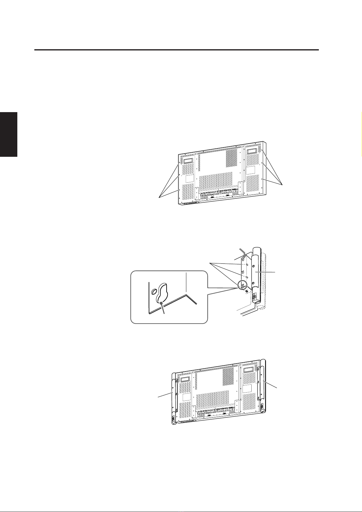
Rückseite
3Lautsprecherhalterung
Auf der Rückseite des
Displays befestigen.
4Lautsprecheranschluss
Schließen Sie diesen
Anschluss mit den
mitgelieferten
Lautsprecherkabeln an den
Lautsprecheranschluss am
Display an.
Zubehör
Überprüfen Sie, ob Sie das ganze Zubehör mitgeliefert wurde. Die in Klammern angegebene Zahl gibt die Menge der
mitgelieferten Stücke an. Sollte etwas fehlen, kontaktieren Sie bitte unverzüglich Ihren Händler.
Frontlautsprecher (L,R)
Kabelklemmen (2)
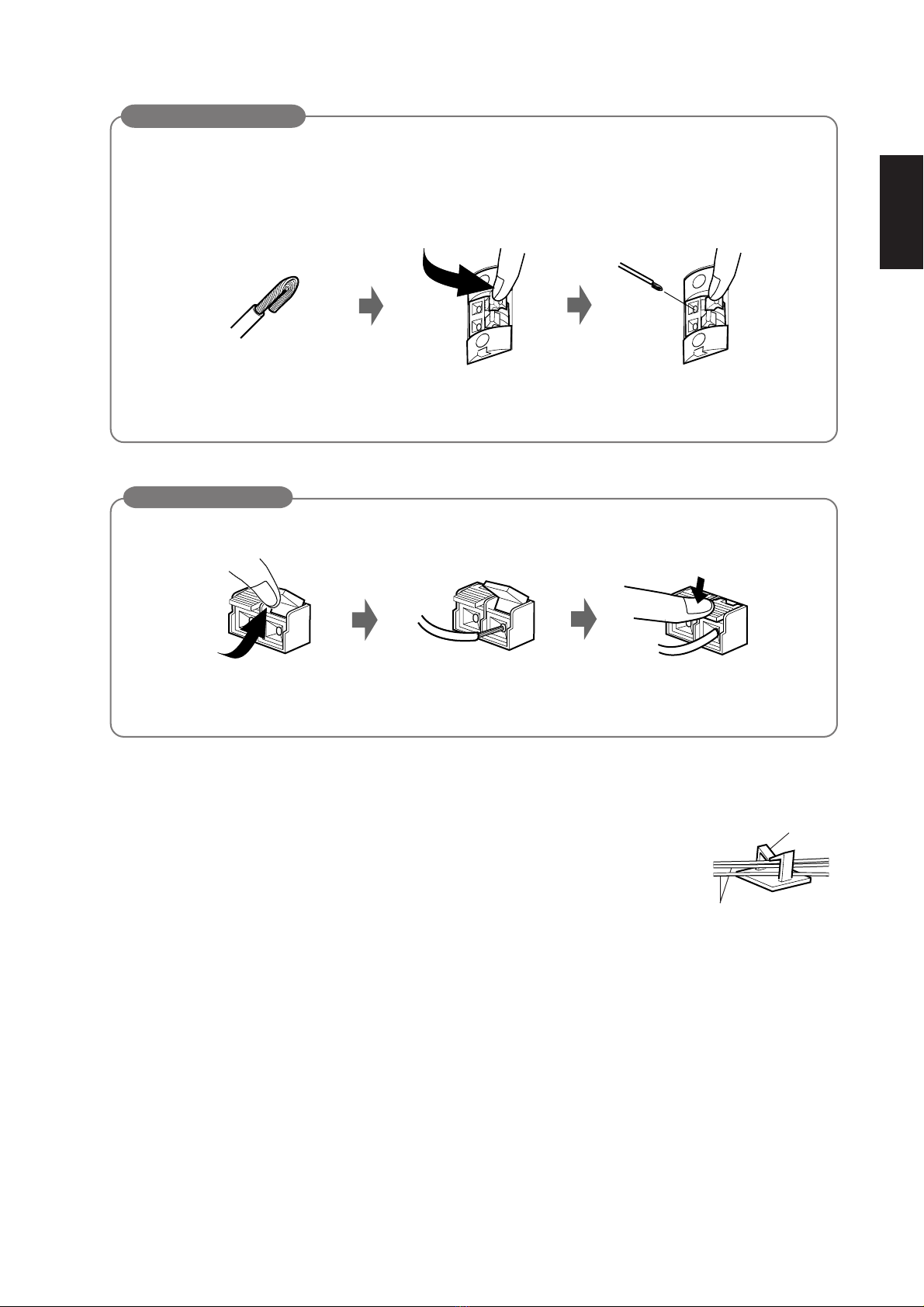
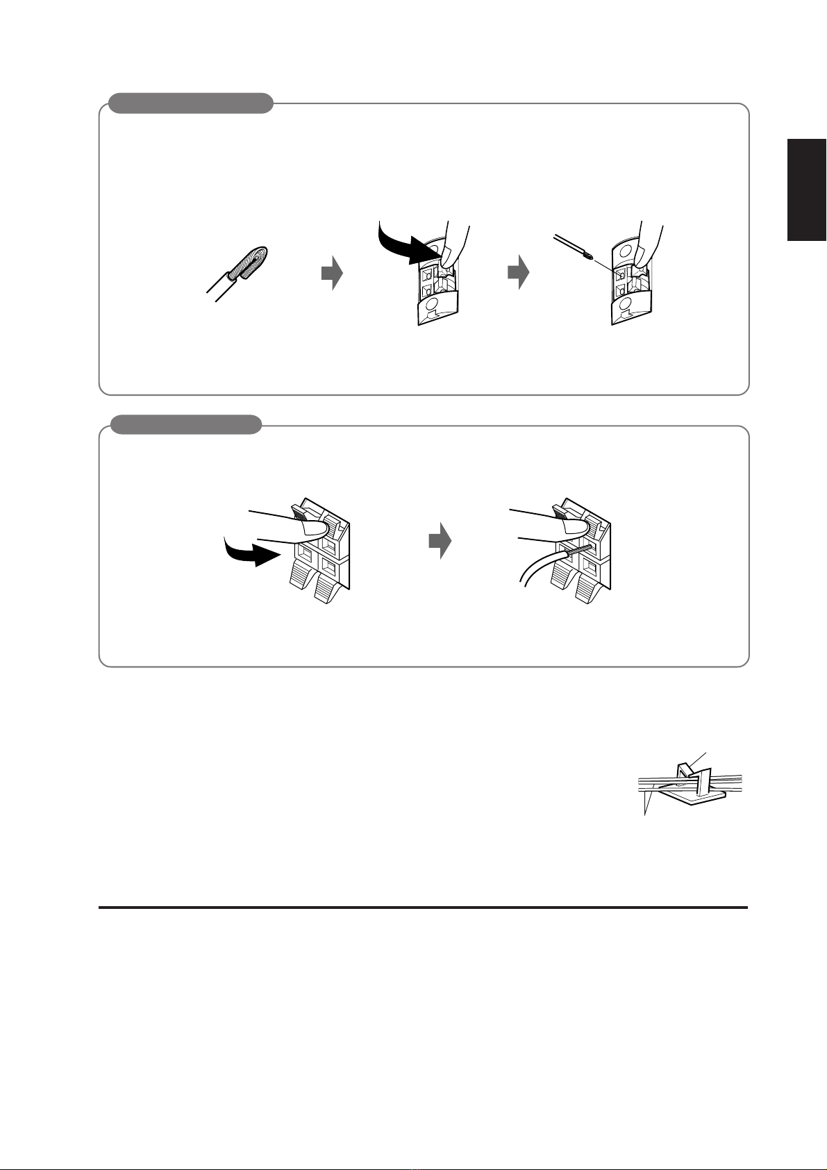
Lautsprecherkabel
(1,2 m x 2)
Allgemeine Vorsichtsmaßnahme
Befestigungsschrauben
(für Displays der Serie
GD-V42XX) (6)
Symbole für
Sicherheitsvorkehrungen
Verschiedene Symbole sind auf dem Produkt und in
dieser Bedienungsanleitung dargestellt.
Diese Symbole sollen Verletzungen und
Materialschäden verhindern. Machen Sie sich vor dem
Lesen dieser Bedienungsanleitung mit der Bedeutung
der Symbole vertraut.
Symbolerklärung
• Dieses Symbol (einschließlich Warnhinweis) weist
darauf hin, dass VORSICHTIG vorgegangen
werden sollte.
• Unzulässige Vorgehensweisen werden durch die
folgenden Symbole dargestellt.
• Vorgehensweisen, die durchgeführt werden sollten
(notwendige und vorgeschlagene Aktionen) werden
durch das folgende Symbol dargestellt.
Nichtbeachtung des Hinweises unter
dem Symbol kann zu Verletzungen
und Materialschäden führen. Es
muss mit äußerster Vorsicht vorge-
gangen werden.
• Die Frontlautsprecher nicht verändern
(zerlegen). Andernfalls besteht Brand- bzw.
Elektroschockgefahr.
Nichtbeachtung des Hinweises unter
dem Symbol kann zu Verletzungen
und Materialschäden führen. Es
muss mit äußerster Vorsicht vorge-
gangen werden.
• Schließen Sie das Netzkabel erst dann an
eine Wandsteckdose an, nachdem alle
anderen notwendigen Geräte
angeschlossen wurden.
Es besteht die Gefahr eines Elektroschocks,
wenn das Netzkabel an eine Wandsteckdose
angeschlossen ist und Geräte angeschlossen
werden.
GE_TS-C421SPGU_1.p65 03.3.20, 6:45 PM1