Kaixin MSU3 User manual

KAIXIN
MSU3
Full Digital Mechanical Sector Scanning
Ultrasonic Diagnostic Instruments (Vet)
User’s Manual
Xuzhou Kaixin Electronic Instrument Co., Ltd.

Full digital mechanical sector scanning ultrasonic diagnostic instruments (Vet) User’s Manual V1.07
F-1
Introduction
Thank you for purchasing MSU3 full digital mechanical sector scanning ultrasonic diagnostic
instruments.
Users shall carefully read through this manual and fully understand the text before operating
the equipment.
Please keep this manual after reading so that you can access at any time when needed.
The user’s manual issue date: December 13, 2019, Version: V1.07
For the changes of appearance, this manual is subject to change without further notice!
Intellectual Property Information
The user’s manual and the corresponding intellectual property rights belonging to Xuzhou
Kaixin Electronic Instrument Company Ltd. (hereinafter referred to as Kaixin).
Individual or organization may not copy, modify or translate any part of this user’s manual,
without the express written permission of Kaixin.
Statement
Kaixin has the final explanation right of this user’s manual.
Kaixin was considered responsible for the safety, reliability and performance in case of
meeting all the following requirements:
1. Assembly, expansion, readjustment, improve and repair are all performed by professionals
recognized by Kaixin;
2. All replacement parts and accessories, consumables involved repairs are Kaixin company
(original) or approved by Kaixin;
3. Related electrical equipment complies with national standards and the requirements of the
user’s manual;
4. Operate the product in accordance with the user’s manual.
Warranty and repair service
Purchased the product warranty, sees the company's service policies.
The qualified service personnel can repair the instrument out of warranty by themselves. But
this should be agreed by Xuzhou Kaixin Electronic Instrument Co., Ltd. We will provide circuit
diagrams, component part lists or other information to assist service personnel to repair those parts
of our equipment that are designated by our company.
Manufacturer’s Information
Xuzhou Kaixin Electronic Instrument Co., Ltd.
Kaixin Mansion, C-01, Economic Development Zone, Xuzhou, Jiangsu, China.
Post Code: 221004
Tel: +86-516-87732932 87733758
Fax: +86-516-87732932 87792848
Website: http://www.kxele.com
E-mail: [email protected]

Full digital mechanical sector scanning ultrasonic diagnostic instruments (Vet) User’s Manual V1.07
F-2
Important Statement
1. User shall be fully responsible for the maintenance and management of this product after
purchasing this product.
2. Even in the warranty period, warranty does not include the following:
a) Damage or loss caused by error or rough using.
b) Damage or loss caused by force majeure (such as fires, earthquakes, floods, or
lightning etc.).
c) Damage or loss caused by not meeting the conditions of use specified by the system,
such as inadequate power supply, incorrect installation or environmental conditions do
not meeting the requirements.
d) Damage or loss caused by not used the system in the initial buy region.
e) Damage or loss caused by the system purchased not by Kaixin or its authorized dealer
or agents.
3. Medical personnel qualified with professional qualifications only to use this system.
4. Do not modify the software or hardware of the equipment without authorization of the
manufacturer.
5. In any case, Kaixin shall not be liable for the problems, damages or losses due to
re-installation, alteration or repair the system by non-Kaixin designated personnel.
6. This product is intended to provide clinical diagnostic data for the doctor.
The doctor shall be responsible for the diagnostic process. Kaixin shall not be liable for
any problems arising out of the process.
7. Be sure to back up important data to external storage media, such as notebooks.
8. Due to operator’s error or abnormal condition causing the data stored in the internal system
is lost, Kaixin is not responsible.
9. This user’s manual contains warnings for predictable dangers. Users shall also exercise
care at any time to be aware of the dangers unforeseen in this manual. Kaixin shall not be
liable for the damages and losses arising out of neglecting to follow the operation
instructions herein described.
10. This user’s manual shall be furnished with the machine so that managerial and operating
personnel can refer to it any time as necessary. Once the managerial personnel of the
system changes, it shall hand over this user’s manual.
11. Deal with the exhausted product according to the local statute.
12. The maintenance and servicing of product shall be performed by the trained engineer or by
Kaixin Electronic Instrument Co., Ltd.

Full digital mechanical sector scanning ultrasonic diagnostic instruments (Vet) User’s Manual V1.07
F-3
Safety Cautions
1. Warning Symbols and Definitions
The following warning symbols are used in this manual to indicate safety level and other
important items. Please remember these symbols and understand the meaning as you read this
user’s manual. These symbols convey specific meanings as detailed in the table below:
Symbols & Words
Connotation
Danger
Indicates an imminent danger that may result in personal death or
serious injury if not avoided.
Warning
Indicates a potential danger that may result in personal injury if not
avoided.
Attention
Indicates a potential danger or unexpected use condition that may result
in light injury or property loss or affecting the use if not avoided.
2. Safety Symbols
Symbols
Meaning
Symbols
Meaning
Type B applied part
Up
Direct current
Keep dry
Power switch
Fragile
Power supply indication
Stacking limit by number
Battery charge indicator
Temperature limits (Storage
and transport)
Adapter connection
indication
Humidity limitation (Storage
and transport)
Follow instructions for use
Atmospheric pressure
limitation (Storage and
transport)
Marking for the separate
collection of electrical and
electronic equipment
Symbol for the marking of electrical and electronics devices according to
Directive 2012/19/EU. The device, accessories and the packaging have to
be disposed of waste correctly at the end of the usage. Please follow Local
Ordinances or Regulations for disposal.

Full digital mechanical sector scanning ultrasonic diagnostic instruments (Vet) User’s Manual V1.07
F-4
Contents
Chapter 1 Technical Specifications........................................................................................ - 1 -
1.1 Technical parameters................................................................................................... - 1 -
1.2 Primary Functions....................................................................................................... - 1 -
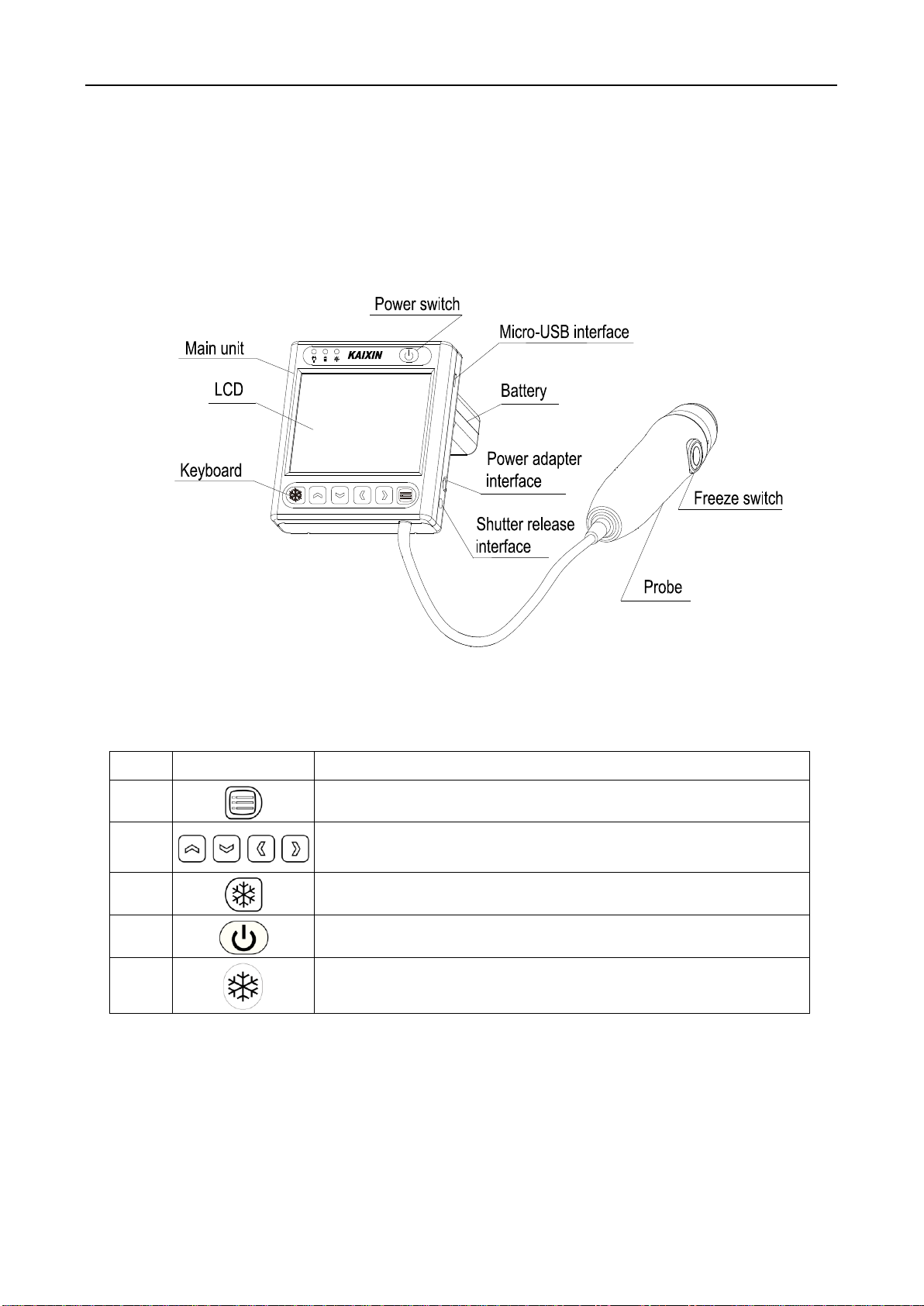
Chapter 2 Product appearance.............................................................................................. - 2 -
2.1 Structure composition of the instrument..................................................................... - 2 -
2.2 Components name....................................................................................................... - 2 -
2.3 Function keys description ........................................................................................... - 2 -
Chapter 3 System Configuration........................................................................................... - 3 -
3.1 Standard Configuration ............................................................................................... - 3 -
3.2 Optional parts.............................................................................................................. - 3 -
Chapter 4 Operation Condition............................................................................................. - 4 -
4.1 Power Requirements ................................................................................................... - 4 -
4.2 Operation Environment............................................................................................... - 4 -
4.3 Transport and Storage.................................................................................................. - 4 -
Chapter 5 System Installation and Check ............................................................................ - 5 -
5.1 System installation ...................................................................................................... - 6 -
5.2 Install/Remove the battery .......................................................................................... - 6 -
5.3 Connection to shutter release ...................................................................................... - 7 -
5.4 Connection to power ................................................................................................... - 7 -
5.5 Ultrasonic probe check before and after operation ..................................................... - 7 -
5.6 Main unit check before and after operation ................................................................ - 7 -
5.6.1 Inspection before start-up......................................................................................................- 7 -
5.6.2 Inspection after start-up.........................................................................................................- 8 -
5.7 System reset................................................................................................................. - 8 -
Chapter 6 Functional Operation............................................................................................ - 9 -
6.1 Startup and Shutdown ................................................................................................. - 9 -
6.2 System Functions Setting............................................................................................ - 9 -
6.2.1 Date setting............................................................................................................................- 9 -
6.2.2 Time setting ...........................................................................................................................- 9 -
6.2.3 Probe protect time setting......................................................................................................- 9 -
6.2.4 Screensaver setting ................................................................................................................- 9 -
6.2.5 Code time setting.................................................................................................................- 10 -
6.2.6 Code BIN setting.................................................................................................................- 10 -
6.2.7 Menu time setting................................................................................................................- 10 -
6.2.8 Chinese-English setting.......................................................................................................- 10 -
6.2.9 Ruler setting.........................................................................................................................- 10 -
6.3 Mode switching......................................................................................................... - 11 -
6.4 Image adjustment ...................................................................................................... - 11 -
6.4.1 Image adjustment in B, 2B mode......................................................................................... - 11 -

Full digital mechanical sector scanning ultrasonic diagnostic instruments (Vet) User’s Manual V1.07
F-5
6.4.1.1 Gain adjustment................................................................................................................ - 11 -
6.4.1.2 Dynamic range adjustment ............................................................................................... - 11 -
6.4.1.3 Near field gain adjustment................................................................................................- 12 -
6.4.1.4 Far field gain adjustment ..................................................................................................- 12 -
6.4.1.5 Curve adjustment..............................................................................................................- 12 -
6.4.1.6 Frequency adjustment.......................................................................................................- 12 -
6.4.1.7 Frame average adjustment................................................................................................- 12 -
6.4.1.8 Color adjustment...............................................................................................................- 12 -
6.4.1.9 Brightness adjustment.......................................................................................................- 13 -
6.4.1.10 Contrast adjustment ........................................................................................................- 13 -
6.4.2 Gain adjustment in A mode..................................................................................................- 13 -
6.5 Depth range selection................................................................................................ - 13 -
6.6 Image freeze/unfreeze............................................................................................... - 13 -
6.7 Image/Data storage and viewing............................................................................... - 13 -
6.7.1 Image/data storage...............................................................................................................- 13 -
6.7.1.1 Save image in B, 2B mode ...............................................................................................- 13 -
6.7.1.2 Save data in A mode .........................................................................................................- 14 -
6.7.2 View image or data..............................................................................................................- 14 -
Chapter 7 Fat thickness and Lean percentage measurement........................................... - 15 -
7.1 Measurement items ................................................................................................... - 15 -
7.2 Backfat measurement................................................................................................ - 15 -
7.3 Measurement of Swine’s lean percentage ................................................................. - 16 -
7.4 Measurement considerations..................................................................................... - 16 -
Chapter 8 System Maintenance........................................................................................... - 17 -
8.1 Maintenance by users................................................................................................ - 17 -
8.1.1 System cleaning and disinfection ........................................................................................- 17 -
8.1.2 Replace the fuse...................................................................................................................- 19 -
8.1.3 Use and maintenance for the rechargeable battery ..............................................................- 19 -
8.2 Replacement of power supply cord........................................................................... - 21 -
8.3 Troubleshooting......................................................................................................... - 21 -
8.4 Periodic Safety Checks.............................................................................................. - 21 -
Chapter 9 Storage and Transportation ............................................................................... - 22 -
Chapter 10 Safety Classification.......................................................................................... - 22 -

Full digital mechanical sector scanning ultrasonic diagnostic instruments (Vet) User’s Manual V1.07
- 1 -
Chapter 1 Technical Specifications
1.1 Technical parameters
1. Gray scale: 256
2. Monitor: 3.5” LCD
3. Adapter rating: 100-240V~, 1.2-0.6A, 50-60Hz (model: BJE01-40-001M)
4. Output of Adapter: DC12.8V 3.0A
5. Main device rating: DC12V 3.0A
6. Main Unit Size: approx. 90 * 98 * 25 (L * M * H, mm)
7. Weight of main unit: approx. 620g (including battery and probe)
1.2 Primary Functions
1. System preset function;
2. Mode conversion function;
3. Adjustment of near field, far field, total gain and dynamic range;
4. Frequency conversion function;
5. Frame correlation function;
6. Compress curve adjustment function;
7. Color display function;
8. Screen brightness and contrast adjustment function;
9. Depth range selection function;
10. Image freeze/unfreeze function;
11. Measurement of backfat thickness, loin thickness and lean percentage;
12. Image and data storage function;
13. Energy saving;
14. Chinese-English switch function.

Full digital mechanical sector scanning ultrasonic diagnostic instruments (Vet) User’s Manual V1.07
- 2 -
Chapter 2 Product appearance
2.1 Structure composition of the instrument
MSU3 full digital mechanical sector scanning ultrasonic diagnostic instruments (Vet) are
composed of main unit and probe, etc.
2.2 Components name
Figure MSU3 main unit sketch map
2.3 Function keys description
SN
Function keys
Function
1
Image parameters menu, System setting menu in frozen status
2
Selection and adjustment of parametes; Mode selection;
Depth selection, etc.
3
Freeze/Unfreeze
4
Power switch
5
Press the Freeze switch to freeze/unfreeze the image.

Full digital mechanical sector scanning ultrasonic diagnostic instruments (Vet) User’s Manual V1.07
- 3 -
Chapter 3 System Configuration
3.1 Standard Configuration
1. Main unit 1 unit
2. 3.5MHz mechanical sector probe 1 PC
3. Power adapter 1 PC
4. Internal battery 1 PC
5. Power cable 1 PC
6. OTG U disk 1PC
7. Velcro straps 1 Set
8. Portable bag 1 PC
9. Shutter release 1 PC
3.2 Optional parts
1. Plastic seal box

Full digital mechanical sector scanning ultrasonic diagnostic instruments (Vet) User’s Manual V1.07
- 4 -
Chapter 4 Operation Condition
4.1 Power Requirements
Adapter rating: 100-240V~, 1.2-0.6A, 50-60Hz
Adapter model: BJE01-40-001M
Output of adapter: DC12.8V 3.0A
Main device rating: DC12V 3.0A
4.2 Operation Environment
Ambient temperature: 10℃-40℃
Relative humidity: 30%-75% (without condensation)
Atmospheric pressure: 800hPa-1060hPa
4.3 Transport and Storage
Ambient temperature: -20℃-55℃
Relative humidity: 30%-93% (without condensation)
Atmospheric pressure: 700hPa-1060hPa
Attention: The main voltage is varies with different countries or regions.
Danger: Do not use this equipment where flammable gas (such as anesthetic gas,
oxygen or hydrogen) or flammable liquid (such as alcohol) are present. Failure to do
so may result in explosion.
Warning: Avoid using this equipment with high-frequency electric knife,
high-frequency therapy equipment or defibrillators and other electronic devices, or
may an electric shock occur to the patient.
Attention: Using radio transmitting equipment nearby the system may interfere
with the normal operation of the system. Prohibited carry or use of devices that can
generate radio waves within the room installed this system, such as cell phones, radio
transceivers and wireless remote control toys.
Attention:System should be avoided using in following environments:
1. Moist 2. Rain 3. Thunderstorm weather
4. No ventilation 5. Close to heat source 6. Direct sunlight
7. Dramatic temperature change 8. Poisonous gas
9. Corrosive gas 10. Strong shock
11. Strong electromagnetic field (e.g. MRI) 12. Radiation (e.g. X-ray, CT)
13. Defibrillators or short wave therapy equipment
Warning: AC/DC adapter is as a part of the equipment, please only use theAC/DC
adapter provided by manufacturer.

Full digital mechanical sector scanning ultrasonic diagnostic instruments (Vet) User’s Manual V1.07
- 5 -
Chapter 5 System Installation and Check
Warning:
1. When instrument works abnormally, do stop working, turn off the power and check
the reason, then contacts the KAIXIN Company about it.
2. Turn off power and pull out of the plug from socket after each ultrasonic diagnostic
operation.
3. Itis forbidden to drag and press the powerand probe cables emphatically; regularly
inspect whether there is pull-apartand bareness, if thereis the phenomena like this,
turn off power supply immediately, stop using it and change it for new one.
4. It is forbidden to load and unload the probe or move the instrument in galvanic to
avoid danger of safety.
5. Pull out of the plug from socket after operation in thunderstorm weather to avoid
the instrument being damaged by lightening.
6. If the temperature changes greatly in short time will cause vapor recovery inside of
instrument, the case may damage the instrument.
7. The equipment is switched completely only by disconnecting the power supply from
the wall socket.
Warning: To avoid the risk of electric shock, this equipment must only be connected
to a supply mains with protective earth.
Warning:
1. All plugs of instruments of this system shall be connected into the power socket
with protectively earth on the wall and the socket must meet the requirement of
power rating of instrument. Use of multiple portable socket-outlets may affect
protective earth to make leakage currents exceed the safety requirements.
2. Please follow the correct electrical connections method to connect the power supply
and earth, otherwise there will be danger of electric shock. Do not connect the
grounding wire to any gas pipe or water pipe, or it may cause bad grounding and
danger of explosion.
3. This equipment is not waterproof, not use this equipment in place where liquid
may into the interior of the equipment. Never pour any liquid on the equipment;
otherwise there will be danger of electric shock or cause equipment damage. If
accidentally spill liquid on the equipment, turn off the power immediately and
contact your local representative.
4. Additional equipment connected to the medical electrical equipment must comply
with the respective IEC or ISO standards (e.g. IEC60950 for data processing
equipment). Furthermore all configurations shall comply with the requirements
for medical electrical systems (see IEC 60601-1-1 or clause 16 of IEC60601-1 3rd,
respectively). Anybody connecting additional equipment to medical electrical
equipment configures a medical system and is therefore responsible that the
system complies with the requirements for medical electrical systems. Attention is
drawn to the fact that local laws take priority over the above mentioned
requirements. When more than one device is connected to use, the accumulation of
leakage current may cause the danger of security. If in doubt, consult your local
representative or the technical service department.
5. Prohibit the live parts of the equipment or other devices (such as various signal
input and output ports, etc.) contact with the patient, if this equipment or other
equipment has failure, the patient will have danger of electric shock.
6. If the integrity of the external protective conductor in the installation or its
arrangement is in doubt, equipment shall be operated from its internal electrical
power source.
Warning: The power adapter, shutter release, battery and power supply cord as
described in this section are replaced by operator. But these parts must be provided by
KAIXIN or his authorized supplier.

Full digital mechanical sector scanning ultrasonic diagnostic instruments (Vet) User’s Manual V1.07
- 6 -
5.1 System installation
Please carefully read through and fully understand the use-method before installing the system,
and check the goods for its completeness according to the packing list furnished. This system
provides the following several usages, for the user to select:
1. Place the instrument on a desktop to use
2. Instrument fixed in the wrist to use
a. Extend your hand into the Velcro straps, the strap worn on the wrist, and then the Velcro
through the back ring;
b. According to arrow direction tighten the Velcro to suitable position then closely fitting.
5.2 Install/Remove the battery
Service personnel or operator can replace the battery. Before replacing the battery, please
contact Kaixin Company; replace the battery under the guidance of Kaixin Company. Please use
the battery provided by Kaixin Company.
1. Install the battery
With four M3*6 pan-head screws fix the battery on the lower case of main unit, paste the
Velcro on the buckle postion, then put the buckle into the battery, at last with two M3*6
pan-head screws fix the buckle on the lower case of main unit, as shown:
Buckle
Battery
the lower case
of main unit
2. Remove the battery
First open the Velcro, remove the straps, and then use a screwdriver to remove two M3*6
pan-head screws to remove the buckle, then unscrew the four M3*6 pan-head screws,
remove the battery.
Attention: when using the Velcro straps, if allergy, please consult a doctor
immediately and increase protective measures (e.g. Wear gloves before use).

Full digital mechanical sector scanning ultrasonic diagnostic instruments (Vet) User’s Manual V1.07
- 7 -
Straps
Buckle
Battery
the lower case
of main unit
5.3 Connection to shutter release
Install shutter release to shutter release interface (Freeze interface) as shown in the figure.
5.4 Connection to power
1. Connect to the power adapter
Insert the output plug of adapter into DC power input port, which is on the right side of
main unit.
2. Connect to the main power supply
Insert the power plug (jack) furnished with the machine into power input socket of the
power adapter, the other end to the mains socket-outlet. The instrument uses three-core
power supply. It connects with the protective earth line when power plug inserts into the
standard power socket.
5.5 Ultrasonic probe check before and after operation
Before and after ultrasonic diagnosis to check if there are any exceptionally on the surface of
the probe or cable jacket, such as peeling, cracks, bulge, or if the acoustic lens is reliable, cleaned
or disinfected.
5.6 Main unit check before and after operation
5.6.1 Inspection before start-up
Check the following items before starting the machine:
Warning:
1. Adapter has no switch. APPLIANCE COUPLER or MAINS PLUG is used as the
intended disconnection device from the supply mains. Do not position the
EQUIPMENT the place where it is difficult to operate the disconnection device.
2. AC/DC adapter is as a part of the equipment, please only use the AC/DC adapter
provided by Kaixin Company.
3. To avoid damaging power adapter or harming people by unexpected fallen, make sure
the power adapter is placed on the leveled desk.
4. The operator must not touch signal input/output and patient simultaneously.
Warning: Do not short-circuit the battery terminals.

Full digital mechanical sector scanning ultrasonic diagnostic instruments (Vet) User’s Manual V1.07
- 8 -
1. The temperature, humidity and atmospheric pressure shall meet the requirements of operation
condition.
2. No condensation occurs.
3. No distortion, damage or contamination on system and peripheral. Clean the parts as specified
in relevant sections, if the contaminant is present.
4. Check the keyboard, LCD screen and enclosure to ensure they are in good working condition
and free of abnormity (such as cracks and loosened screws).
5. No damage on cables (e.g. power cable, etc.), and not loose the connection.
6. Check probe and its connections to ensure they are free of abnormity (such as scuffing,
drop-off or contamination). If the contaminant is present, clean, disinfect the contaminated
objects as specified in relevant sections.
7. See to it that probe has been cleaned, disinfected; else dispose it as specified in relevant sections.
8. Check all the ports of the machine for possible damage or blockage.
9. Clean the field and environment.
5.6.2 Inspection after start-up
Check the following items after starting the machine:
1. No abnormal voice, strange smell and overheating appear.
2. Check the machine to ensure a normal start-up: The power indication light is on; the
machine will automatically enter B mode.
3. Check the acoustic lens for abnormal heat when the probe is in use. This can be done by
hand touching the probe to feel the temperature of the lens.
4. Check the image to ensure trouble-free display (e.g. no excessive noise or flicker).
5. Check the keyboard to ensure normal operation condition.
6. Check the instrument to ensure that thephenomenon of too high local temperature will not appear.
5.7 System reset
In case of abnormal screen display or no-working for system operation, turn off the power and
try to restart the system.
Attention: Thoroughly clean the coupling gel on the probe surface each time after
ultrasonic operation, or the coupling gel may become hardened on the acoustic lens of the
probe, deteriorating quality of image.
Attention: If the overheat acoustic lens is placed on the patient’s skin, heat injury may occur.

Full digital mechanical sector scanning ultrasonic diagnostic instruments (Vet) User’s Manual V1.07
- 9 -
Chapter 6 Functional Operation
6.1 Startup and Shutdown
In shutdown status, hold down key, machine starts up, power indicator lights.
In startup status, hold down key, machine shuts down, power indicator goes out.
6.2 System Functions Setting
In B, 2B mode and in frozen status can be set as follows:
6.2.1 Date setting
1. Press key and then press key to enter “System Set”menu;
2. Press or key to move the cursor to “Date”item, and then press or key to adjust
the date;
3. Press key to confirm the date setting and quit system setting interface.
6.2.2 Time setting
1. Press key and then press key to enter “System Set”menu;
2. Press or key to move the cursor to “Time”item, and then press or key to adjust
the time;
3. Press key to confirm the time setting and quit system setting interface.
6.2.3 Probe protect time setting
1. Press key and then press key to enter “System Set”menu;
2. Press or key to move the cursor to “Probe Time”item, and then press or key to
adjust the probe protect time;
3. Probe protect time is “0-99”minutes, “0”stands for turn off the probe protection;
4. Press key to confirm this setting and quit system setting interface.
Note: In real-time status, the probe will be automatically frozen when the system reaches the
time of probe protection, press key to freezeand return to normal operation status.
6.2.4 Screensaver setting
1. Press key and then press key to enter “System Set”menu;
2. Press or key to move the cursor to “Screensaver”item, and then press or key to
adjust the screensaver time;

Full digital mechanical sector scanning ultrasonic diagnostic instruments (Vet) User’s Manual V1.07
- 10 -
3. Screensaver time is “0-99”minutes, “0”stands for turn off the screensaver;
4. Press key to confirm this setting and quit system setting interface.
Note: Go beyond the system setting screensaver time without pressing any key, the
machine will automatically enter a black screen status. Press any key, the system
will return to normal operation status.
6.2.5 Code time setting
1. Press key and then press key to enter “System Set”menu;
2. Press or key to move the cursor to “Code Time”item, and then press or key to
adjust the ear tag waiting time;
3. Ear tag waiting time (Code Time) is “10-30”seconds;
4. Press key to confirm this setting and quit system setting interface.
Explanation: The ear tag scanning function is to be upgraded.
6.2.6 Code BIN setting
1. Press key and then press key to enter “System Set”menu;
2. Press or key to move the cursor to “Code BIN”item, and then press or key to
choose the ear tag format;
3. Ear tag formats have three, namely “EM4305”, “EM4100”and “T5557”;
4. Press key to confirm this setting and quit system setting interface.
Explanation: The ear tag scanning function is to be upgraded.
6.2.7 Menu time setting
1. Press key and then press key to enter “System Set”menu;
2. Press or key to move the cursor to “Menu Time”item, and then press or key to
adjust the menu disappear time;
3. Menu disappear time is “5-30”seconds;
4. Press key to confirm this setting and quit system setting interface.
6.2.8 Chinese-English setting
1. Press key and then press key to enter “System Set”menu;
2. Press or key to move the cursor to “Langue”item, and then press or key to
choose Chinese or English;
3. Press key to confirm this setting and quit system setting interface.
6.2.9 Ruler setting
1. Press key and then press key to enter “System Set”menu;
2. Press or key to move the cursor to “Ruler”item, and then press or key to adjust
the value;
3. Ruler has three status, “0”shows no ruler, “1”shows 10mm-spacing dot-like ruler, “2”
shows horizontal and vertical 10mm-spacing dot-like ruler;
4. Press key to confirm this setting and quit system setting interface.
Note:
1. During set above items, you can press key to exit the “System Set”menu at any time and
give up the settings.
2. The above settings can be finished at once after entering “System Set”menu, and then exit.

Full digital mechanical sector scanning ultrasonic diagnostic instruments (Vet) User’s Manual V1.07
- 11 -
6.3 Mode switching
Diagnostic modes have 3 kinds, which respectively are B, 2B and A. B mode is default after
starting up.
1. Press key to start up, the system will automatically enter into B mode;
2. Press key to enter 2B mode, the left side of the screen displays single B-mode real-time
image;
3. Press key again, the left image is frozen, the right of the screen displays real-time image;
4. Press key again to enter A mode;
5. Press key again to return to B mode;
6. Repeatedly press key to achieve the cycle conversion among the B, 2B, A mode.
Note: Repeatedly press key also to achieve the cycle conversion among the B, A, 2B
mode.
6.4 Image adjustment
6.4.1 Image adjustment in B, 2B mode
In B, 2B mode and in real-time status, you can adjust images’gain, dynamic range, near field,
far field, compression curve, frequency, framge average, color, brightness and contrast.
6.4.1.1 Gain adjustment
1. Press key to enter image adjustment menu, press or key to enter “GN”item;
2. Press or key to adjust the parameter within “27~90”; Press direction key to
increase image total gain and press direction key to reduce total gain so as to control the
total gain of the entire image.
3. After waitting for 5-30s (“Menu Time”set in the System Set), the parameters will be saved
and exit the image adjustment menu.
6.4.1.2 Dynamic range adjustment
1. Press key to enter image adjustment menu, press or key to enter “Dyn”item;

Full digital mechanical sector scanning ultrasonic diagnostic instruments (Vet) User’s Manual V1.07
- 12 -
2. Press or key to adjust the parameter within “27~90”; Press direction key to
increase the value of dynamic range and press direction key to decrease the value of
dynamic range so as to control the dynamic range of the entire image.
3. After waitting for 5-30s (“Menu Time”set in the System Set), the parameters will be saved
and exit the image adjustment menu.
6.4.1.3 Near field gain adjustment
1. Press key to enter image adjustment menu, press or key to enter “Near”item;
2. Press or key to adjust the parameter within “-31~0”; Press direction key to
increase near field gain and press direction key to reduce near field gain so as to control
the gain in near field region.
3. After waitting for 5-30s (“Menu Time”set in the System Set), the parameters will be saved
and exit the image adjustment menu.
6.4.1.4 Far field gain adjustment
1. Press key to enter image adjustment menu, press or key to enter “Far”item;
2. Press or key to adjust the parameter within “0~31”; Press direction key to
increase far field gain and press direction key to reduce far field gain so as to control the
gain in far field region.
3. After waitting for 5-30s (“Menu Time”set in the System Set), the parameters will be saved
and exit the image adjustment menu.
6.4.1.5 Curve adjustment
1. Press key to enter image adjustment menu, press or key to enter “Curve”item;
2. Press or key to adjust the parameter within “0~3”;
3. After waitting for 5-30s (“Menu Time”set in the System Set), the parameters will be saved
and exit the image adjustment menu.
6.4.1.6 Frequency adjustment
1. Press key to enter image adjustment menu, press or key to enter “Freq.”item;
2. Press or key to switch the frequency between 2.5MHz and 3.5MHz;
3. After waitting for 5-30s (“Menu Time”set in the System Set), the parameters will be saved
and exit the image adjustment menu.
6.4.1.7 Frame average adjustment
1. Press key to enter image adjustment menu, press or key to enter “FAvg”item;
2. Press or key to adjust the parameter within “0~5”;
3. After waitting for 5-30s (“Menu Time”set in the System Set), the parameters will be saved
and exit the image adjustment menu.
6.4.1.8 Color adjustment
1. Press key to enter image adjustment menu, press or key to enter “Color”item;
2. Press or key to adjust the parameter within “0~7”, realize conversion among eight
sets of colors (including one set of black and white);

Full digital mechanical sector scanning ultrasonic diagnostic instruments (Vet) User’s Manual V1.07
- 13 -
3. After waitting for 5-30s (“Menu Time”set in the System Set), the parameters will be saved
and exit the image adjustment menu.
6.4.1.9 Brightness adjustment
1. Press key to enter image adjustment menu, press or key to enter “Bright”item;
2. Press or key to adjust the parameter within “0~8”, adjust the screen brightness;
3. After waitting for 5-30s (“Menu Time”set in the System Set), the parameters will be saved
and exit the image adjustment menu.
6.4.1.10 Contrast adjustment
1. Press key to enter image adjustment menu, press or key to enter “Con”item;
2. Press or key to adjust the parameter within “0~8”, adjust the screen contrast;
3. After waitting for 5-30s (“Menu Time”set in the System Set), the parameters will be saved
and exit the image adjustment menu.
Note: The above parameters can be finished at once after entering image adjustment menu,
and then exit.
6.4.2 Gain adjustment in A mode
1. In A mode and in real-time status, press key to enter gain adjustment status;
2. Press or key to adjust the gain within “27~90”;
3. After waitting for 5-30s (“Menu Time”set in the System Set), the parameters will be saved
and exit the gain adjustment status.
6.5 Depth range selection
In B, 2B mode and in real-time status, press or key to obtain the images of different
depth. It has three kinds of depth range selection, namely 126, 163, 200.
6.6 Image freeze/unfreeze
In real-time mode, press key to freeze the image, the lower right corner of the image displays
“FRZ”; in frozen status, press key to unfreeze the image.
6.7 Image/Data storage and viewing
6.7.1 Image/data storage
6.7.1.1 Save image in B, 2B mode
1. Insert OTG U disk into the Micro-USB interface at the right side of main unit, the lower left
corner of the screen appears “U Disk”prompt;
2. Press key to freeze the image;
3. Press key, then press or key to record the pregnancy status, Y(Yes), N (No), TBD
(To Be Determined);
Description: “Y”represents pregnant, “N”represents not pregnant, and “TBD”
indicates uncertainty pregnancy.
4. Press key, the system issued “tick, tick”tones, namely the current image and EXCEL
spreadsheet stored in the “IMAGE”folder of the U disk;

Full digital mechanical sector scanning ultrasonic diagnostic instruments (Vet) User’s Manual V1.07
- 14 -
5. Press key to return to the real-time status.
Note 1: The “IMAGE”folder includes “images folder”and “EXCEL”spreadsheet.
Note 2: The “images folder”is automatically named by the machine current date; the
image is automatically named by the machine current time.
Note 3: “EXCEL”spreadsheet is automatically named by the machine current date.
Note 4: The EXCEL spreadsheet records the pregnancy status for each inspection
according to chronological order. In the EXCELspreadsheet, the contents of
each column respectively: serial number, Ear tag, check date, check time, and
pregnancy status.
Note 5: For the ear tag function, to be upgraded. The Ear tag is expressed as
A000000000000 in the “EXCEL”spreadsheet.
Such as:
U:\IMAGE\20160217\082736.bmp
It represents that at 08:27:36 on Feburary 17, 2016 and on the storage path
U:\IMAGE\20160217, save a “082736.bmp”image.
U:\IMAGE\20160114.csv
It represents that on January 14, 2016, on the storage path U:\IMAGE, save
a “20160114.csv”EXCEL spreadsheet.
6.7.1.2 Save data in A mode
1. Insert OTG U disk into the Micro-USB interface at the right side of main unit, the lower left
corner of the screen appears “U Disk”prompt;
2. Complete the A-mode measurement, freeze the image;
3. Press key, the system issued a “tick”tone, namely the current data is stored in the
EXCEL spreadsheet in the “DATA”folder of the U disk;
4. Press key to return to the real-time status.
Note 1: The “DATA”folder includes “EXCEL”spreadsheet. EXCELspreadsheet is
automatically named by the machine current date. For example, the machine
current time is January 18, 2016; the file name of EXCEL spreadsheet is
20160118.
Note 2: The EXCEL spreadsheet records the results for each measurement in the order.
In the EXCEL spreadsheet, the contents of each column respectively: Ear tag,
check date, check time, measurement site P1/P2/P3, the weight of swine, lean
percentage, the backfat thickness and loin thickness.
Note 3: For the ear tag function, to be upgraded. The Ear tag is expressed as
A000000000000 in the “EXCEL”spreadsheet.
6.7.2 View image or data
Insert OTG U disk to computer to view the stored images or data.
This manual suits for next models
1
Table of contents
Other Kaixin Diagnostic Equipment manuals