Kaixin RKU10 User manual

KAIXIN
RKU10
Full Digital Ultrasonic Diagnostic
Instruments (Vet)
User’s Manual
Xuzhou Kaixin Electronic Instrument Co., Ltd.

Full digital ultrasonic diagnostic instruments (Vet) User’s Manual V2.24
Introduction
Thank you for purchasing RKU10 full digital ultrasonic diagnostic instruments.
Users shall carefully read through this manual and fully understand the text before operating the
equipment.
Please keep this manual after reading so that you can access at any time when needed.
The user’s manual issue date: June 9, 2022, Version: V2.24
For the changes of appearance, this manual is subject to change without further notice!
Intellectual Property Information
The user’s manual and the corresponding intellectual property rights belonging to Xuzhou Kaixin
Electronic Instrument Company Ltd. (hereinafter referred to as Kaixin).
Individual or organization may not copy, modify or translate any part of this user’s manual, without
the express written permission of Kaixin.
Statement
Kaixin has the final explanation right of this user’s manual.
Kaixin was considered responsible for the safety, reliability and performance in case of meeting all
the following requirements:
1. Assembly, expansion, readjustment, improve and repair are all performed by professionals
recognized by Kaixin;
2. All replacement parts and accessories, consumables involved repairs are Kaixin company
(original) or approved by Kaixin;
3. Related electrical equipment complies with national standards and the requirements of the user’s
manual;
4. Operate the product in accordance with the user’s manual.
Warranty and repair service
Purchased the product warranty, sees the company's service policies.
Manufacturer’s Information
Xuzhou Kaixin Electronic Instrument Co., Ltd.
Kaixin Mansion, C-01, Economic Development Zone, Xuzhou, Jiangsu, China.
Post Code: 221004
Tel: +86-516-87732932 87733758
Fax: +86-516-87732932 87792848
Website: http://www.kxele.com
E-mail: info@kxele.com
F-1

Full digital ultrasonic diagnostic instruments (Vet) User’s Manual V2.24
Important Statement
1. User shall be fully responsible for the maintenance and management of this product after
purchasing this product.
2. Even in the warranty period, warranty does not include the following:
a) Damage or loss caused by error or rough using.
b) Damage or loss caused by force majeure (such as fires, earthquakes, floods, or lightning etc.).
c) Damage or loss caused by not meeting the conditions of use specified by the system, such as
inadequate power supply, incorrect installation or environmental conditions do not meeting
the requirements.
d) Damage or loss caused by not used the system in the initial buy region.
e) Damage or loss caused by the system purchased not by Kaixin or its authorized dealer or
agents.
3. Medical personnel qualified with professional qualifications only to use this system.
4. Do not modify the software or hardware of the equipment without authorization of the
manufacturer.
5. In any case, Kaixin shall not be liable for the problems, damages or losses due to re-installation,
alteration or repair the system by non-Kaixin designated personnel.
6. This product is intended to provide clinical diagnostic data for the doctor.
The doctor shall be responsible for the diagnostic process. Kaixin shall not be liable for any
problems arising out of the process.
7. Be sure to back up important data to external storage media, such as notebooks.
8. Due to operator’s error or abnormal condition causing the data stored in the internal system is lost,
Kaixin is not responsible.
9. This user’s manual contains warnings for predictable dangers. Users shall also exercise care at any
time to be aware of the dangers unforeseen in this manual. Kaixin shall not be liable for the
damages and losses arising out of neglecting to follow the operation instructions herein described.
10. This user’s manual shall be furnished with the machine so that managerial and operating
personnel can refer to it any time as necessary. Once the managerial personnel of the system
changes, it shall hand over this user’s manual.
11. Deal with the exhausted product according to the local statute.
12. The maintenance and servicing of product shall be performed by the trained engineer or by Kaixin
Electronic Instrument Company Ltd.
F-2

Full digital ultrasonic diagnostic instruments (Vet) User’s Manual V2.24
Safety Cautions
1. Warning Symbols and Definitions
The following warning symbols are used in this manual to indicate safety level and other important
items. Please remember these symbols and understand the meaning as you read this user’s manual. These
symbols convey specific meanings as detailed in the table below:
Symbols & Words
Connotation
Danger Indicates an imminent danger that may result in personal death or serious
injury if not avoided.
Warning Indicates a potential danger that may result in personal injury if not avoided.
Attention Indicates a potential danger or unexpected use condition that may result in
light injury or property loss or affecting the use if not avoided.
Indicates that make sure refer to relevant contents in this manual.
2. Safety Symbols
Symbols
Meaning Symbols
Meaning
Type B applied part
Keep dry
Power supply indication
Fragile
Direct current
Stacking limit by number
Follow instructions for use
Temperature limits
Up
Humidity limitation
Marking for the separate collection of
electrical and electronic equipment
Atmospheric pressure limitation
3. Labels
Label Description
Attention:
Battery use should note the
precautions.
Symbol for the marking of electrical and electronics devices according to
Directive 2012/19/EU. The device, accessories and the packaging have to be
disposed of waste correctly at the end of the usage. Please follow Local
Ordinances or Regulations for disposal.
F-3

Full digital ultrasonic diagnostic instruments (Vet) User’s Manual V2.24
Contents
Chapter One Technical Specifications………………………………………………………………1
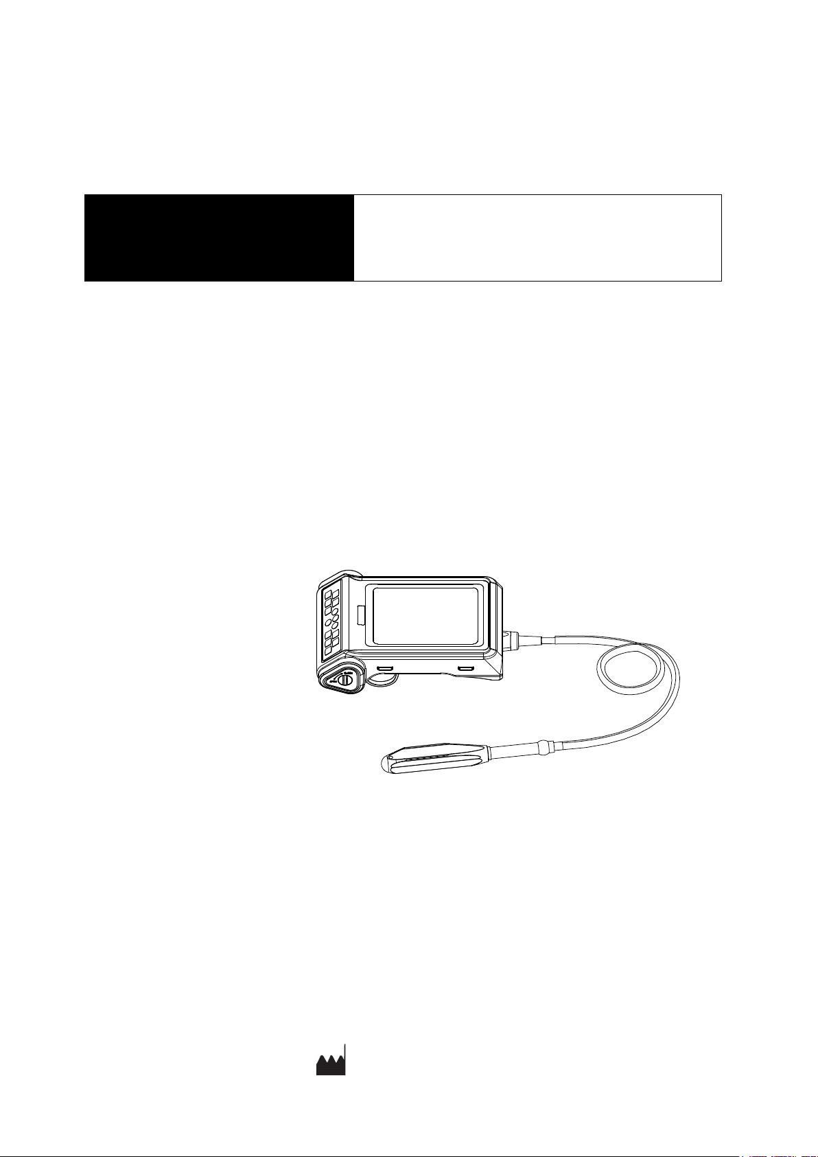
Chapter Two System Outline………………………………………………………………………2
2.1 Structure composition of the instrument……………………………………………………2
2.2 Components name……………………………………………………………………………2
2.3 Parts of the probe……………………………………………………………………………2
2.4 Function keys description………………………………………………………………….. 2
Chapter Three System Configuration………………………………………………………………3
Chapter Four Operation Condition………………………………………………………………4
Chapter Five System Installation and Check…………………………………….……………5
5.1 System installation…………………………………………………………………………6
5.2 Ultrasonic probe installation…………………………………………………………………7
5.3 Install/Remove the battery………………………………………………………………7
5.4 Video glasses installation……………………………………………………………………8
5.5 Video recorder installation……………………………………………………………………8
5.6 Connect to power………………………………………………………………………………8
5.7 Ultrasonic probe check before and after operation…………………………………………8
5.8 Main unit check before and after operation…………………………………………………9
5.9 System reset…………………………………………………………………………………9
Chapter Six Functional Operation………………………………………………………………..10
6.1 Startup and Shutdown…………………………………………………………………………10
6.2 Screen display reverse……………………………………………………………………10
6.3 System Functions Setting……………………………………………………………………10
6.3.1 Time Setting…………………………………………………………………………………10
6.3.2 TV Mode Setting……………………………………………………………………………10
6.3.3 Energy Saving Setting………………………………………………………………………10
6.3.4 Characters Brightness Setting………………………………………………………………10
6.3.5 Hospital Name Setting………………………………………………………………………10
6.3.6 Key Sound Setting…………………………………………………………………………11
6.3.7 Compression Curve Setting…………………………………………………………………11
6.3.8 Grid Setting…………………………………………………………………………………11
6.4 Mode selection………………………………………………………………………………11
6.4.1 B Mode……………………………………………………………………………………12
6.4.2 B/B Mode…………………………………………………………………………………12
6.4.3 4B Mode……………………………………………………………………………………12
6.4.4 B/M Mode…………………………………………………………………………………12
6.4.5 M Mode…………………………………………………………………………………12
6.5 Image Quality Adjustment………………………………………………………………12
6.5.1 Brightness and Contrast Adjustment………………………………………………………12
6.5.2 Total Gain Adjustment……………………………………………………………………13
6.5.3 Near Field Gain Adjustment………………………………………………………………13
6.5.4 Far Field Gain Adjustment………………………………………………………………13
6.5.5 Dynamic Range Adjustment………………………………………………………………13
6.5.6 Frequency Adjustment (Frequency conversion)…………………………………………13
6.5.7 Focus Adjustment and Control……………………………………………………………13
6.5.8 Frame Correlation Adjustment……………………………………………………………13

Full digital ultrasonic diagnostic instruments (Vet) User’s Manual V2.24
6.5.9 Image Post-process Adjustment……………………………………………………………13
6.5.10 Edge Enhancement Adjustment……………………………………………………………13
6.6 Image Control…………………………………………………………………………………13
6.6.1 Magnification Selection……………………………………………………………………13
6.6.2 Depth Range Selection and Depth Enhancement………………………………………14
6.6.3 Local Zoom and Local Additive Color……………………………………………………14
6.6.4 Image Left/right Reverse……………………………………………………………………14
6.6.5 Image Up/down Reverse……………………………………………………………………14
6.6.6 Image Negative……………………………………………………………………………14
6.6.7 Ruler (Automatic Backfat Measure)………………………………………………………14
6.6.8 Color Selection………………………………………………………………………………15
6.6.9 Scan Range (Angle/Width Change)………………………………………………………15
6.6.10 Image Filter…………………………………………………………………………………15
6.6.11 Image Freeze/Unfreeze……………………………………………………………………15
6.7 Puncture guide line and lithotripsy positioning line………………………………………15
6.8 Body Mark and Probe Mark………………………………………………………………15
6.9 Image storage and recall……………………………………………………………………16
6.9.1 Save image…………………………………………………………………………………16
6.9.2 Open image…………………………………………………………………………………16
6.10 Single dump and mass dump…………………………………………………………17
6.11 Delete the image………………………………………………………………………18
6.12 Image review………………………………………………………………………………18
6.13 Cine loop……………………………………………………………………………………18
6.14 Text Input……………………………………………………………………………………18
6.15 Obstetric list management…………………………………………………………………19
Chapter Seven General Measurement……………………………………………………………21
7.1 Distance Measurement ………………………………………………………………………21
7.2 Fat thickness Measurement…………………………………………………………………21
7.3 Circumference/Area/Volume Measurement…………………………………………………22
7.4 Slope/Heart rate/Cycle Measurement………………………………………………………23
Chapter Eight Obstetric Measurement…………………………………………………………24
8.1 Measurement and Calculation items………………………………………………………24
8.2 Measurement of GA and EDC………………………………………………………………24
8.3 Measurement of Swine’s lean percentage…………………………………………………24
8.4 Obstetric report ……………………………………………………………………………..25
8.5 Measurement items…………………………………………………………………………..25
Chapter Nine System Maintenance……………………………………………………………26
9.1 Maintenance by users………………………………………………………………………26
9.1.1 System cleaning and disinfection…………………………………………………………26
9.1.2 Use and maintenance for the rechargeable battery…………………………………………28
9.2 Troubleshooting………………………………………………………………………………29
9.3 Periodic Safety Checks………………………………………………………………………30
Chapter Ten Storage and Transportation………………………………………………………31
Chapter Eleven Safety Classification……………………………………………………………31

Full digital ultrasonic diagnostic instruments (Vet) User’s Manual V2.24
-
1
-
Chapter One Technical Specifications
1.1 Technical Data
1. Gray scale: 256
2. Monitor: 5.7” LED
3. Adapter ratings: 100-240V~, 1.2-0.6A, 50-60Hz (model: BJE01-40-001M)
4. Output of adapter: DC12.8V 3.0A
5. Main device rating: DC12V 3.0A
6. Main Unit Size: approx. 212 * 154 * 50mm3 (L * W * H)
7. Weight of main unit: approx. 1.1kg (excluding accessories)
1.2 Primary Functions
1. Mode conversion function.
2. Magnification conversion function.
3. Frequency conversion function.
4. Frame correlation function.
5. Image post-process function.
6. Edge enhancement function.
7. Image freeze/unfreeze.
8. Depth range selection function.
9. Depth heighten function.
10. Color display function.
11. Local zooming.
12. Angle/width change.
13. Image filter function.
14. Automatic backfat measure function.
15. Adjustment and display of near field, far field, total gain and dynamic range.
16. Single-point, multi-point focusing.
17. Image storage.
18. Vertical, horizontal reverse and B/W conversion.
19. Case information, image annotation and auto time display.
20. Body marks.
21. Measurement of distance, fat thickness, circumference, area, volume, slope, heart rate and cycle.
22. OB software package including 25 tables about 8 kinds of animals, automatic calculation of GA
and EDC.
23. Puncture guide.
24. Cine loop.
25. PAL-NTSC conversion.
26. Energy saving.
27. Grid setting.
28. Obstetric report.

Full digital ultrasonic diagnostic instruments (Vet) User’s Manual V2.24
-
2
-
Chapter Two System Outline
2.1 Structure composition of the instrument
RKU10 full digital ultrasonic diagnostic instruments (Vet) are composed of main unit, probe, etc.
2.2 Components name
Left ring Right ring
Heatsink insulation grid
USB interface
Video output interface
Power input interface
Battery cover
knob
LED
Main unit
Keyboard
Probe
Fig. RKU10 main unit sketch map
2.3 Parts of the probe (Take 6.5MHz animal transrectal linear array probe for example)
Fig. Parts name of 6.5MHz animal transrectal linear array probe
Name
Function
(1) Acoustic lens
To convert electric signal to ultrasonic signal based on principle of
converse
piezoelectric effect. The ultrasonic signal, after entering the human body, is
reflected as echo wave and converted to electric signal again. The acoustic
lens is on the probe surface. Supply ultrasonic coupling gel to the acoustic
lens surface when performing ultrasonic diagnosis.
(2) Cable To connect the probe to the probe connector.
(3) Probe connector To connect the probe to ultrasonic diagnostic system.
2.4 Function keys description
SN.
Function keys
Real-time mode function Freeze mode function
1
Mode Selection Text Input, dump image, select local/U disk
2
Enter Confirm
3
Main-menu / Cine loop
4
Freeze/Unfreeze,
Hold down
freeze
key
for
some
time
to
achieve
screen
display
up/down
reverse
.
5
Direction Keys
6
Quit
7
Power switch
1
2
3

Full digital ultrasonic diagnostic instruments (Vet) User’s Manual V2.24
-
3
-
Chapter Three System Configuration
3.1 Typical configuration
1. Main unit 1 unit
2. 6.5MHz animal transrectal linear array probe 1 PC
3. Power adapter 1 PC
4. Internal battery 1 PC
5. Charger 1 PC
6. Strap 1 PC
7. Socket screwdriver 1 PC
8. Soft rubber jacket 1 PC
9. Hood 1 Set (A, B, C)
10. Plastic sealed box 1 PC
11. Battery lock coin 2PCS
3.2 Optional parts
1. 3.5 MHz convex array probe
2. 4.0 MHz convex array transrectal probe
3. 6.5 MHz micro-convex probe
4. 6.5 MHz intra-cavity probe
5. 7.5 MHz high frequency linear array probe
6. Video recorder
7. Video glasses
8. Battery (5200mAH)
9. Probe holder
10. Probe telescopic frame

Full digital ultrasonic diagnostic instruments (Vet) User’s Manual V2.24
-
4
-
Chapter Four Operation Condition
4.1 Power supply
Adapter ratings: 100-240V~, 1.2-0.6A, 50-60Hz
Adapter model: BJE01-40-001M
Output of adapter: DC12.8V 3.0A
Main device rating: DC12V 3.0A
4.2 Operation environment
Ambient temperature: 10℃-40℃
Relative humidity: 30%-75% (without condensation)
Atmospheric pressure: 700hPa-1060hPa.
Altitude: < 2000 m
Overvoltage: Overvoltage CategoryⅡ
Pollution degree: 2
4.3 Storage and transport
Ambient temperature: -20℃-55℃
Relative humidity: 30%-93% (without condensation)
Atmospheric pressure: 700hPa-1060hPa
Attention: System should be avoided using in following environments:
1. Moist 2. Rain 3. Thunderstorm weather
4. No ventilation 5. Close to heat source 6. Direct sunlight
7. Dramatic temperature change 8. Poisonous gas
9. Corrosive gas 10. Strong shock
11. Strong electromagnetic field (e.g. MRI) 12. Radiation (e.g. X-ray, CT)
13. Defibrillators or short wave therapy equipment
Attention: The main voltage is varies with different countries or regions.
Danger: Do not use this equipment where flammable gas (such as anesthetic gas, oxygen
or hydrogen) or flammable liquid (such as alcohol) are present. Failure to do so may
result in explosion.
Warning: Avoid using this equipment with high-frequency electric knife,
high-frequency therapy equipment or defibrillators and other electronic devices, or may
an electric shock occur to the patient.
Attention: Using radio transmitting equipment nearby the system may interfere with
the normal operation of the system. Prohibited carry or use of devices that can generate
radio waves within the room installed this system, such as cell phones, radio transceivers
and wireless remote control toys.

Full digital ultrasonic diagnostic instruments (Vet) User’s Manual V2.24
-
5
-
Chapter Five System Installation and Check
Warning: To avoid the risk of electric shock, this equipment must only be connected to a
supply mains with protective earth.
Warning:
1. When instrument works abnormally, do stop working, turn off the power and check the
reason, then contacts the KAIXIN Company about it.
2. Turn off power and pull out of the plug from socket after each ultrasonic diagnostic
operation.
3. It is forbidden to drag and press the power and probe cables emphatically; regularly
inspect whether there is pull-apart and bareness, if there is the phenomena like this, turn
off power supply immediately, stop using it and change it for new one.
4. It is forbidden to load and unload the probe or move the instrument in galvanic to avoid
danger of safety.
5. Pull out of the plug from socket after operation in thunderstorm weather to avoid the
instrument being damaged by lightening.
6. If the temperature changes greatly in short time will cause vapor recovery inside of
instrument, the case may damage the instrument.
7. The instrument is turned off completely only by disconnecting the power supply from the
wall socket.
Warning:
1. All plugs of instruments of this system shall be connected into the power socket with
protectively earth on the wall and the socket must meet the requirement of power rating
of instrument. Use of multiple portable socket-outlets may affect protective earth to
make leakage currents exceed the safety requirements.
2. Please follow the correct electrical connections method to connect the power supply and
earth, otherwise there will be danger of electric shock. Do not connect the grounding
wire to any gas pipe or water pipe, or it may cause bad grounding and danger of
explosion.
3. This equipment is not waterproof, not use this equipment in place where liquid may into
the interior of the equipment. Never pour any liquid on the equipment; otherwise there
will be danger of electric shock or cause equipment damage. If accidentally spill liquid
on the equipment, turn off the power immediately and contact your local representative.
4. Prohibit the live parts of the equipment or other devices (such as various signal input
and output ports, etc.) contact with the patient, if this equipment or other equipment has
failure, the patient will have danger of electric shock.
5. Additional equipment connected to the medical electrical equipment must comply with
the respective IEC or ISO standards (e.g. IEC60950 for data processing equipment).
Furthermore all configurations shall comply with the requirements for medical electrical
systems (see IEC 60601-1-1 or clause 16 of IEC60601-1 3rd, respectively). Anybody
connecting additional equipment to medical electrical equipment configures a medical
system and is therefore responsible that the system complies with the requirements for
medical electrical systems. Attention is drawn to the fact that local laws take priority
over the above mentioned requirements. When more than one device is connected to use,
the accumulation of leakage current may cause the danger of security. If in doubt,
consult your local representative or the technical service department.
6. If the integrity of the external protective conductor in the installation or its arrangement
is in doubt, equipment shall be operated from its internal electrical power source.

Full digital ultrasonic diagnostic instruments (Vet) User’s Manual V2.24
-
6
-
5.1 System installation
Please carefully read through and fully understand the use-method before installing the system, and
check the goods for its completeness according to the packing list furnished. This system provides the
following several usages, for the user to select:
1. Place the instrument on the arm to use
The instrument can be placed on the arm to use for two states: on the right arm or left arm. Right ring
or left ring is respectively set on the right thumb or left thumb, hold the instrument as shown in the figure
below.
Fig. Use in right arm Fig. Use in left arm
2. Instrument hanging on the chest to use
1) Install the hoods A, B and C as the following fig.
Finish the installation of hood
The sequency and
direction of installation
Hood 1 Hood 2 Hood 3
Fig. Install the hood
2) The installed hood should be inserted the “Hood buckle position” aligned with the side of the
instrument, and then be inserted into the other side. Note: The force should be uniform.
3) Take out the attached strap; install it on the “the hook of hood” or put it on the “the hole of strap” of
the instrument as shown in the figure below.
4) Adjust the length of strap hanging on the neck to meet the requirements of the screen visual angle.
Adjustable strap
the position of strap hole
the hook of hood
the hook of hood
Hood buckle position
Fig. Hang on the chest to use
Attention: When using the soft rubber jacket, if allergy, please consult a doctor
immediately and increase protective measures (e.g. Wear gloves before use).

Full digital ultrasonic diagnostic instruments (Vet) User’s Manual V2.24
-
7
-
5.2 Ultrasonic probe installation
.
5.2.1 Ultrasonic probe connection
Insert the probe connector into the probe socket in the back of the main unit;
5.2.2 Ultrasonic probe disconnection
Socket screwdriver
Button position
on both side of socket
According to arrow direction,
gently insert the socket
screwdriver, then button up the
button position on both side of the
socket with your fingers, you can
remove the probe socket.
Fig. Remove the probe
5.3 Install/Remove the battery
1. Install the battery
Place the main unit on the plane, according to the direction shown (finger upward direction, the plate
of battery toward right) put the battery into battery storage of main unit, cover the “Battery cover”
into the corresponding position, and put “Battery lock coin” into the groove of the “Battery cover
knob”, and then toggle the “Battery cover knob” according to “CLOSE” direction of arrow to lock
the “Battery cover”.
Warning: Before connecting or using the probe, make sure that the probe, connecting
cable and connector are in normal condition (free of cracks or drop). Use of defective
probe may cause electric shock.
Turn off the system, and use socket
screwdriver to remove the probe with
figure’s method and instructions.
Warning:
1. Do not use the probe not provided by our company, otherwise the equipment and the
probe will cause damage, and may cause fire in extreme cases.
2. Check the ultrasonic probe and connecting cable after diagnostic operation. Use of
defective probe may cause electric shock.
3. Do not strike the probe; using the damaged probe may cause electric shock to the patient.
4. Unauthorized disassembly of the probe shall be prohibited as it may cause electric shock.
Attention:
1. Turn off the ultrasonic system before disconnecting the probe. Disconnecting the probe
with system power on may damage the system or probe.
2. Before disconnecting the probe, place the cable and probe on a stable and leveled
position so that the probe may not be damaged or injury person by unexpected fall.
3. Freeze the instrument when instrument is start-up without operation to increase of
service life of probe.
4. Repeat available machine time should be more than 5 minutes to avoid turn on/off
power supply in short time.
Ribbons is on the right
Finger upward direction

Full digital ultrasonic diagnostic instruments (Vet) User’s Manual V2.24
-
8
-
2. Remove the battery
According to the “OPEN” direction of the arrow, use the “Battery lock coin” to toggle “Battery cover
knob”, removed “Battery cover”, pull the ribbon and take out the battery.
Battery Battery cover
Battery cover knob
5.4 Video glasses installation
Turn off the system; connect the video signal line of video glasses to the “Video output interface” of
the main unit, and then connect the USB line of video glasses to the “USB interface” of the main unit.
5.5 Video recorder installation
1. Turn off the system, connect the equipotential terminal ( ) of the video recorder to the earthing;
2. Connect one end of the video connection line to the video recorder and the other end to the video
output interface of the main unit;
3. Insert one end of power plug (jack) of the video recorder to the power input socket of the video
recorder, the other end to the power supply socket.
5.6 Connect to power
1. Connect to the power adapter
Insert the output plug of adapter into DC power input interface.
2. Connect to the main power supply
Insert the power plug (jack) furnished with the machine into power input socket of the power adapter,
the other end to the mains socket-outlet. The instrument uses three-core power supply. It connects
with the protective earth line when power plug inserts into its socket.
5.7 Ultrasonic probe check before and after operation
Before and after ultrasonic diagnosis to check if there are any exceptionally on the surface of the probe
or cable jacket, such as peeling, cracks, bulge, or if the acoustic lens is reliable, disinfected or cleaned.
5.8 Main unit check before and after operation
5.8.1 Inspection before start-up
Check the following items before starting the machine:
1. The temperature, humidity and atmospheric pressure shall meet the requirements of operation
condition.
2. No condensation occurs.
3. No distortion, damage or contamination on system and peripheral. Clean the parts as specified in
relevant sections, if the contaminant is present.
4. Check the control panel, LED screen and enclosure to ensure they are in good working condition and
Warning:
1. Adapter has no switch. APPLIANCE COUPLER or MAINS PLUG is used as the
isolation means from the SUPPLY MAINS. Not to position the EQUIPMENT so that it
is difficult to operate the disconnection device.
2. The device should be used only with power adapter provided by Kaixin Company.
3. To avoid damaging power adapter or harming people by unexpected fallen, make sure
the power adapter is placed on the leveled desk.
4. The operator must not touch signal input/ signal output and patient simultaneously.

Full digital ultrasonic diagnostic instruments (Vet) User’s Manual V2.24
-
9
-
free of abnormity (such as cracks and loosened screws).
5. No damage on power cable, and hard up on its connection.
6. Check probe and its connections to ensure they are free of abnormity (such as scuffing, drop-off or
contamination). If the contaminant is present, clean, disinfect the contaminated objects as specified
in relevant sections.
7. No barriers around the intake of equipment.
8. See to it that probe has been cleaned, disinfected; else dispose it as specified in relevant sections.
9. Check all the ports of the machine for possible damage or blockage.
10. Clean the field and environment.
5.8.2 Inspection after start-up
Check the following items after starting the machine:
1. No abnormal voice, strange smell and overheating appear.
2. Check the machine to ensure a normal start-up: The power indication light is on and startup picture is
shown on the screen. Then the machine will be automatically set in B mode.
3. Check the acoustic lens for abnormal heat when the probe is in use. This can be done by hand
touching the probe to feel the temperature of the lens.
4. Check the image to ensure trouble-free display (no excessive noise or flicker).
5. Check the control panel to ensure normal operation condition.
6. Check the instrument to ensure that the phenomenon of local high temperature will not appear.
5.9 System reset
In case of abnormal screen display or no-working for system operation, try to restart the system by
turning on/off the main unit power.
Attention: If the overheat acoustic lens is placed on the patient’s skin, heat injury may
occur.
Attention: Thoroughly clean the coupling gel on the probe surface each time after
ultrasonic operation, or the coupling gel may become hardened on the acoustic lens of the
probe, deteriorating quality of image.

Full digital ultrasonic diagnostic instruments (Vet) User’s Manual V2.24
-
10
-
Chapter Six Functional Operation
6.1 Startup and Shutdown
In shutdown status, press key, machine starts up, power indicator lights.
In startup status, press key, machine shuts down, power indicator goes out. Please note that when
shut down the machine, the time of pressing key is a rather long than normal pressing key.
6.2 Screen display reverse
Hold down freeze key for some time to achieve the screen display reverse, to meet left/right hand
use.
6.3 System Functions Setting
6.3.1 Time Setting
1. Press key to enter main-menu and press direction keys to move cursor to “Preset”;
2. Press direction keys to enter setting interface;
3. Press direction keys to select “Minutes, Hours, Day, Month and Year”;
4. When setting minutes, hours, day, month and year, press direction key to increase value or press
direction key to decrease value;
5. Press key to confirm the time setting and quit setting interface.
6.3.2 TV Mode Setting
1. Press key to enter main-menu and press direction keys to move cursor to “Preset”;
2. Press direction keys to enter setting interface;
3. Press direction keys to move symbol “<” to point to “TV mode”;
4. Press direction keys to achieve TV mode conversion between PAL and NTSC;
5. Press key to quit setting interface.
6.3.3 Energy Saving Setting
1. Press key to enter main-menu and press direction keys to move cursor to “Preset”;
2. Press direction keys to enter setting interface;
3. Press direction keys to move symbol “<” to point to “Sleep”;
4. Press direction keys to select energy saving time among 01~99 minutes or select “Off”;
5. Press key to quit setting interface.
6.3.4 Characters Brightness Setting
1. Press key to enter main-menu and press direction keys to move cursor to “Preset”;
2. Press direction keys to enter setting interface;
3. Press direction keys to move symbol “<” to point to “Font Bright”;
4. Press direction keys to select characters brightness among 160, 192, 224 and 255;
5. Press key to quit setting interface.
6.3.5 Hospital Name Setting
1. Press key to enter main-menu and press direction keys to move cursor to “Preset”;
2. Press direction keys to enter setting interface;
3. Press direction keys to move symbol “<” to point to “Hospital”;

Full digital ultrasonic diagnostic instruments (Vet) User’s Manual V2.24
-
11
-
4. Press key, the cursor is located above “ID”; at the same time characters input menu will be
shown at the bottom of the screen:
Caps 0 1 2 3 4 A B C D E F G H I J K L M
Shift 5 6 7 8 9 N O P Q R S T U V W X Y Z
Press direction keys to move cursor to point to Caps, and then press key to achieve capital and
small letter conversion; If the cursor point to Shift, press key to achieve the conversion between
the letter and punctuation;
5. Press direction keys to choose “numbers” or “characters” and press key to confirm;
6. If need modify the content, press key to quit the character input menu, press direction
keys to delete input content; press key again to retype;
7. Press key to save this setting and quit setting interface.
6.3.6 Key Sound Setting
1. Press key to enter main-menu and press direction keys to move cursor to “Preset”;
2. Press direction keys to enter setting interface;
3. Press direction keys to move symbol “<” to point to “Key Sound”;
4. Press direction keys to select between “On” and “Off”;
5. Press key to quit setting interface.
6.3.7 Compression Curve Setting
1. Press key to enter main-menu and press direction keys to move cursor to “Preset”;
2. Press direction keys to enter setting interface;
3. Press direction keys to move symbol “<” to point to “Compression Curve”;
4. Press direction keys to select compression curve among “00” –“07”;
5. Press key to quit setting interface.
Note: If use 3.5MHz or 4.0MHz probe, it is recommended to choose 04; if use 6.5MHz or 7.5MHz
probe, recommend choose 00.
6.3.8 Grid Setting
1. Press key to enter main-menu and press direction keys to move cursor to “Preset”;
2. Press direction keys to enter setting interface;
3. Press direction keys to move symbol “<” to point to “Grid set”;
4. Press direction keys to select “00”-“08”; “00” shows “no grid”, “01” shows “line grid”, “02”
shows “dot grid”, “03” shows 10mm-spacing dot-like scale, “04” shows 2mm-spacing dot-like scale,
“05” show 10mm-spacing and 2mm-spacing dot-like scales, “06” shows longitudinal 1mm-spacing
grid in the 1.5/1.6/2.0/2.4/3.0 magnification, “07” shows longitudinal 5mm-spacing grid, “08” shows
longitudinal 10mm-spacing grid;
5. Press key to quit setting interface.
Note: Grid is displayed on B mode after has been set.
6.4 Mode selection
In real-time mode, press key repeatedly to achieve mode switching of B, B/B, 4B, B/M and M.

Full digital ultrasonic diagnostic instruments (Vet) User’s Manual V2.24
-
12
-
6.4.1 B Mode
B mode is a basic operation mode after startup and a single-framed B mode image is displayed.
6.4.2 B/B Mode
1. In real-time mode, press key to enter B/B mode.
2. B/B image switch. Press key to enter main-menu and press direction keys to move the
cursor to “B/B Mode” and then press direction keys to switch image display; the selected
image is activated and the other one is frozen.
3. In real-time mode, press key to exit B/B mode.
6.4.3 4B Mode
1. In real-time mode, press key to enter 4B mode.
2. 4B image switch. Press key to enter main-menu and press direction keys to move the cursor
to “4B Mode”, then press direction keys to switch display among four images; the selected
image is activated and the other three are frozen.
3. In real-time mode, press key to exit 4B mode.
6.4.4 B/M Mode
1. In real-time mode, press key to enter B/M mode.
2. Change of scan mode. Press key to enter main-menu and press direction keys to move
cursor to “M Mode” and then press direction keys to change the M ultra-scan mode.
3. Move sample line. Press key to quit the current using status for direction keys. Press direction
keys to move sample line.
4. In real-time mode, press key to exit B/M mode.
6.4.5 M Mode
1. In real-time mode, press key to enter M mode.
2. Change of M-scan mode: Press key to enter main-menu and press direction keys to move
cursor to “M Mode” and then press direction keys to change the M ultra-scan mode.
3. Change of M speed: Press key to enter main-menu and press direction keys to move cursor
to “M Speed” and then press direction keys to select the eight kinds of scan speed.
4. In real-time mode, press key to exit M mode.
6.5 Image Quality Adjustment
6.5.1 Brightness and Contrast Adjustment
In the startup default status, press freeze key to unfreeze, press key to quit the current using status of
direction keys, the adjustment bars of brightness and contrast will be displayed on the screen by pressing
direction keys , adjust them according to actual need. Press direction key to increase brightness and
contrast, direction key to decrease them; press direction keys to select brightness or contrast
adjustment.
Note: In normal operation, it can adjust brightness and contrast; if not be adjusted with
direction keys , you must exit current use status for direction keys.

Full digital ultrasonic diagnostic instruments (Vet) User’s Manual V2.24
-
13
-
6.5.2 Total Gain Adjustment
In real-time mode, press key to enter main-menu and press direction keys to move cursor to
“Gain” in the display area. Press direction key to increase image total gain and direction key to reduce
total gain so as to control the total gain of the entire image.
6.5.3 Near Field Gain Adjustment
In real-time mode, press key to enter main-menu and press direction keys to move cursor to
“Near” in the display area. Press direction key to increase near field gain and direction key to reduce
near field gain so as to control the gain in near field region.
6.5.4 Far Field Gain Adjustment
In real-time mode, press key to enter main-menu and press direction keys to move cursor to
“Far” in the display area. Press direction key to increase far field gain and direction key to reduce far
field gain so as to control the gain in far field region.
6.5.5 Dynamic Range Adjustment
In real-time mode, press key to enter main-menu and press direction keys to move cursor to
“Dyn” in the display area. Press direction key to increase the value of dynamic range and direction
key to decrease the value of dynamic range so as to control the dynamic range of the entire image.
6.5.6 Frequency Adjustment (Frequency conversion)
In real-time mode, press key to enter main-menu and press direction keys to move cursor to
“Freq.” in the display area. Press direction keys to achieve frequency conversion.
6.5.7 Focus Adjustment and Control
In real-time B, B/B or 4B mode, press key to enter main-menu and move cursor to “F. num” and
then press direction keys to choose from the four focus modes of stage 1(Full process dynamic focus),
2, 3 and 4.
In real-time B, B/B, 4B, B/M or M mode, press key to quit menu mode, press direction
keys again to move the focus up and down.
Note: In B/M or M mode, only allowed choosing single focus mode.
6.5.8 Frame Correlation Adjustment
In real-time B, B/B, 4B or B/M mode, press key to enter main-menu and press direction
keys to move cursor to “Frame Avg” in the display area. Press direction keys to achieve four
levels of frame correlation.
6.5.9 Image Post-process Adjustment
In real-time mode, press key to enter main-menu and press direction keys to move cursor to
“IP” in the display area and then press direction keys to obtain corrected image. System default is 2.
6.5.10 Edge Enhancement Adjustment
In real-time mode, press key to enter main-menu and press direction keys to move cursor to
“Edge” in the display area and then press direction keys to gain four levels of sharpened images.
System default is 0.
6.6 Image Control
6.6.1 Magnification Selection
In real-time mode, press key to enter main-menu and move cursor to “Zoom” and then press

Full digital ultrasonic diagnostic instruments (Vet) User’s Manual V2.24
-
14
-
direction keys to choose eight kinds of magnification.
6.6.2 Depth Range Selection and Depth Enhancement
In real-time B, B/B mode, press key to enter main-menu and press direction keys to move
cursor to “Depth” in the display area and then press direction keys to select depth, press key to
quit depth range selection.
Note: There is no depth range selection function when main unit connecting the probe, which its
nominal frequency greater than or equal to 6.5MHz.
In real-time B, B/B, B/M or M mode, press key to enter main-menu and press direction
keys to move cursor to “Upgrade” in the display area and then press direction keys , “ ”
appears on the screen. Press direction keys to move image up/down or left/right so as to observe the
images of different depth and width. Press key to quit depth heighten status.
6.6.3 Local Zoom and Local Additive Color
In real time mode, press key to enter main-menu and press direction keys to move cursor to
“Local Zoom” in the display area and then press direction keys , a box appears. Press direction keys
to move the box to the position to be enlarged, the selected image be enlarged; Press key to quit local
zoom status.
In the color display, the selected image which by above mentioned operation will be enlarged and
added color.
6.6.4 Image Left/right Reverse
In real-time mode and in B, B/B, 4B or B/M mode, press key to enter main-menu and press
direction keys to move cursor to “HRev” and then press direction keys to achieve image
horizontal reverse. The image horizontal reverse is the change of probe scanning direction. The probe
scanning direction is indicated by the arrow on the upper left area of the image.
6.6.5 Image Up/down Reverse
In real-time mode, press key to enter main-menu and press direction keys to move cursor to
“VRev” and then press direction keys to achieve image vertical reverse.
6.6.6 Image Negative
In real-time B/B, 4B, B/M or M mode, press key to enter main-menu and press direction
keys to move cursor to “Image POS” and then press direction keys to achieve negative function.
6.6.7 Ruler (Automatic Backfat Measure )
1. In real-time B mode, press key to enter main-menu and press direction keys to move cursor
to “Ruler” in the display area and then press direction keys to turn on or turn off the automatic
backfat measure. “0” means: turn off the automatic backfat measure; “1” means: turn on the
automatic backfat measure.
2.Press key, freeze the desired image, a vertical dotted line of fat thickness measurement appears in
the middle of screen, the backfat measurement value is automatically displayed at the “+:----mm” on
the right side of the screen.
3.Press direction keys to choose “Clear” in display area and press key to clear all marks and
data;
4. Press key to unfreeze, clear all marks and data and quit the measurement status.
Other manuals for RKU10
1
Table of contents
Other Kaixin Diagnostic Equipment manuals

Kaixin
Kaixin MSU1 User manual

Kaixin
Kaixin RKU10 User manual

Kaixin
Kaixin DCU10 User manual

Kaixin
Kaixin KX5600L User manual

Kaixin
Kaixin DCU10 User manual

Kaixin
Kaixin DCU12 User manual

Kaixin
Kaixin MSU2 User manual

Kaixin
Kaixin KX5600 User manual

Kaixin
Kaixin MSU1Plus User manual

Kaixin
Kaixin K10 User manual