KDK V56VK User manual

Ceiling Fan
Ventilador
de techo
nI WËdnI WËd
nI WËdnI WËd
nI WËd
Model Number
Número del Modelo
qœu*« r—qœu*« r—
qœu*« r—qœu*« r—
qœu*« r—
V56VK
®
CEILING FAN
MIN
SPEED
TIMER
AUTO
YURAGI
ON
AUTO
OFF/ON
SPEED
OFF/ON
RESET
LAMP
OFF/ON
h
MAX
SLEEP
MODE
OFF/ON
OFF TIMER
CANCEL SET
SLEEP MODE
Operating And Installation
Instructions
Instrucciones de Instalación y Uso
qOGAA«Ë VOd« ULOKFqOGAA«Ë VOd« ULOKF
qOGAA«Ë VOd« ULOKF
Use only with rated voltage.
Utilícelo sólo con el voltaje especificado.
Switch off power supply and wait until the Blade is fully static, before cleaning or doing any
maintenance jobs.
Desconecte la alimentación eléctrica y espere hasta que el Aspa esté totalmente estática, antes
de realizar cualquier limpieza o mantenimiento.
This appliance is not intended for use by persons (including children) with reduced physical,
sensory or mental capabilities, or lack of experience and knowledge, unless they have been
given supervision or instruction concerning use of the appliance by a person responsible for their
safety. Children should be supervised to ensure that they do not play with the appliance.
Este aparato no está pensado para el uso por personas (incluyendo niños) con capacidades
mentales, sensoriales o físicas reducidas, o falta de experiencia y conocimiento, a menos que se
les haya dado control o formación en relación al uso apropiado por una persona responsable de
su seguridad. Los niños deberían estar controlados para asegurar que no juegan con el aparato.
Before operating this set, please read these instructions completely.
Antes de utilizar este aparato, por favor lea totalmente estas instrucciones.
To avoid the possibility of causing injury to users or damage to properties, please follow all the
explanation written in this manual.The manufacturer will not be responsible for any accidents and injuries
caused by defective, deficient installation or installation which does not follow to instruction manual.
Para evitar la posibilidad de causar lesiones a usuarios o daños a propiedades, por favor siga
todas las indicaciones que aparecen escritas en este manual. El fabricante no se
responsabilizará por ningún accidente o lesión causados por una instalación incorrecta,
insuficiente, o que no se realice de acuerdo con este manual de instrucciones.
Æ…—bI*« WODuH« vK jI WËd*« qLF«
ÆqU qJA ULOKF« Ác …¡«d vd ¨WËd*« Ác qOGA q
ÆWËd*« WUO ‰UL« s qL Í« ¡«d« Ë« nOEM q ¨WKU …—uB WËd*« WA— nu v dE«Ë WOzUdNJ« WUD« bËe qB«
rbM bu ô sc« Ë« ¨WOKIF« UUô« ÍË– Ë« 5UF ©‰UHô« v« WU{ôU® ’U« q s ‰ULFö WBB dO WËd*« Ác
Æ’Uô« ¡ôu Wö s ‰u h q s WËd*« …cN oKF ULOKF Ë« œU—« rbM ÊU «–« ô≈ ¨WdF Ë« …d
M
Ò
s ‰u dO lUB« ÆVOJ« «c w »uJ*« ÕdA« ŸU« vd ¨UJKLLK Ë« 5KLF*« ’Uö UËd ‰uB WOUJ« V
ÆVOJ« «c ULOKF l o«u ô Íc« VOd« Ë« hUM« VOd«Ë ¨qDF« s W*« UËd'«Ë Àœ«u W«
V56VK MidEast 1-8.p65 11/7/08, 1:33 PM1

WARNING ATENCIÓN
To avoid the possibility of causing injury to users or damage to properties, please follow all the explanations written below.
Para evitar la posibilidad de causar lesiones a usuarios o daños a propiedades, por favor siga todas las indicaciones que aparecen escritas abajo.
M
Ò
ÆqHô« w »uJ*« ÕdA« ŸU« vd ¨UJKLLK Ë« 5KLF*« ’Uö UËd ‰uB WOUJ« V
SAFETY AND PRECAUTION
PRECAUCIÓN Y SEGURIDAD
Do not dismantle the ceiling fan
unless stated by this manual.
Must use original accessories.
No desmonte el ventilador del techo
salvo si se indica en este manual.
Deberá utilizar accesorios originales.
ÆVOJ« «c w `{u u UL ô≈ nI« WËd pOJH ‰ËU% ô
ÆWOKô« UIK*« ‰ULF« V
Can cause fire, electrical shock,
ceiling fan drops and injuries.
En caso contrario, podría causar un
incendio, descarga eléctrica, caída
del ventilador del techo, y lesiones.
WËd*« ◊uI ¨WOzUdN Wd{ ¨od p– V Ê« sJ1
ÆUËd ‰uBË
Follow strictly to all the instructions
given in this manual for installation.
Installation error can cause fire, electrical
shock, ceiling fan drops and injuries.
Cualquier error de instalación puede
causar un incendio, descarga eléctrica,
caída del ventilador del techo y lesiones.
ÆUËd ‰uBË WËd*« ◊uI ¨WOzUdN Wd{ ¨od TU)« VOd« V Ê« sJ1
Ceiling fan must be mounted above
2.5m from the floor and 1m from the
wall to the Blade.
Can cause injury if hit the Blades.
Can cause unstable air flow and affect
the ceiling fan to wobble.
Si golpea las Aspas, puede causar
lesiones. Tal acción podría provocar
una circulación inestable del aire y
hacer temblar el ventilador del techo.
ÆWËd*« «dH —«b'« »U« «–« UËd qB Ê« sJ1
WËd vK dR Ë XU dO ¡«u ob p– V Ê« sJ1
Æ¡«œô« w »cc UNKFË nI«
More than 1m
Más de 1 m
d ± s d!«
Switch off all power supply before
installation and maintenance.
Desconecte toda la alimentación eléctrica
antes de la instalación y mantenimiento.
ÆWËd*« nOEMË VOd q WOzUdNJ« WUD« bËe qB«
This product is not provided with cord
and plug or with other means for
disconnection from the supply.
Este producto no incluye cable y
enchufe u otros medios para su
desconexión eléctrica.
Ëe dO WËd*« Ác
Ò
Èd« qzUË W« Ë« fUË pK …œ
ÆWOzUdNJ« WUD« —bB s UNKBH
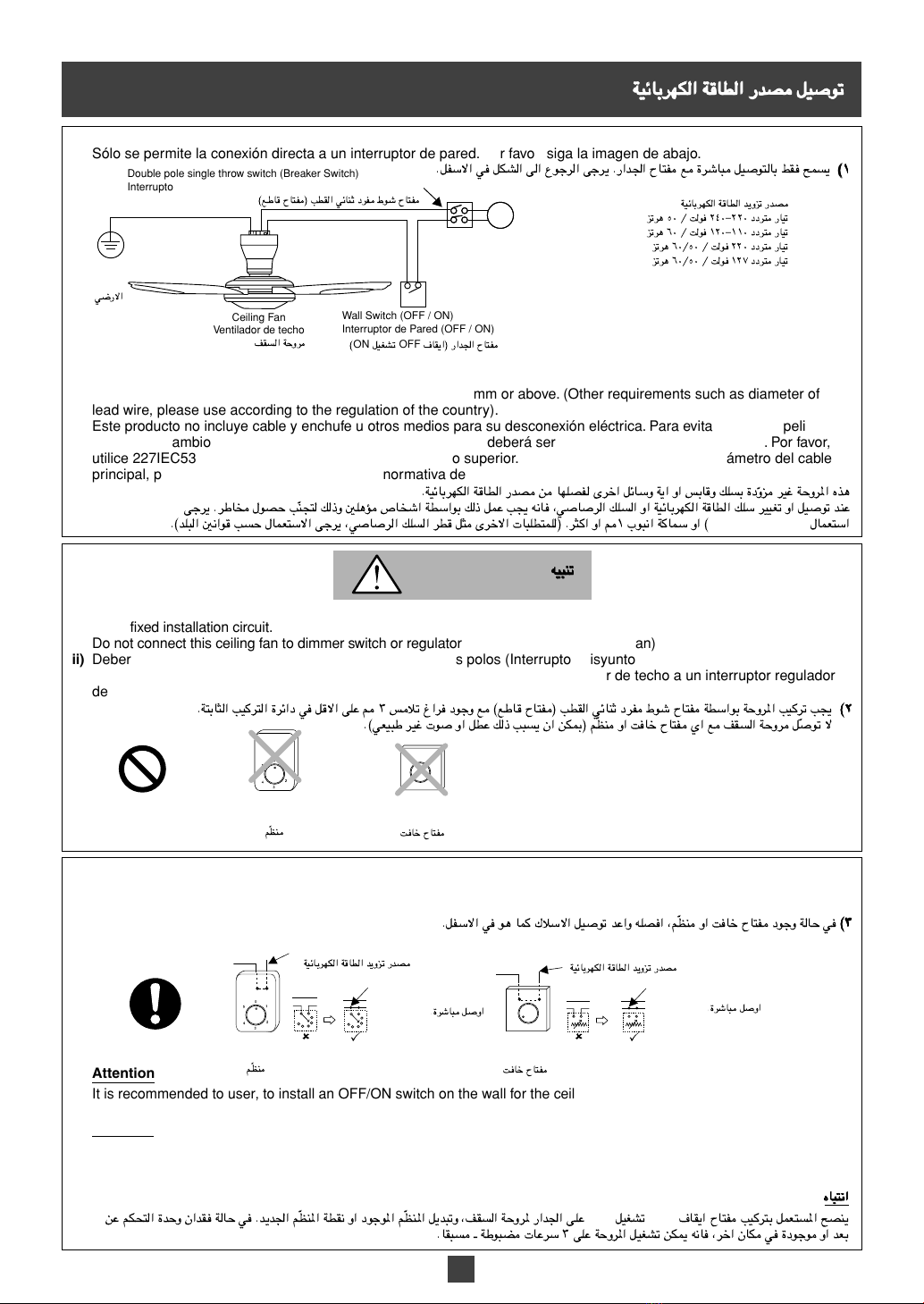
It should be installed with a
double poles single throw switch
(breaker switch) with minimum 3mm
contact gap in the fixed installation circuit.
Debería instalarse con un interruptor
unidireccional de dos polos (interruptor disyuntor)
con un espacio de contacto de un mínimo de 3
mm. en el circuito de instalación fijado.
©lU ÕUH® VDI« wzUM œdH ◊u ÕUH WD«u WËd*« VOd V
ÆWU!« VOd« …dz«œ w qô« vK 3 ≥ fö ⁄«d œuË l
Can cause ceiling fan to move
suddenly, injuries and electrical shock.
Kindly refer to your sales agent for repairing.
En caso contrario, podría causar lesiones y
descarga eléctrica, o provocar que el ventilador
del techo se moviese repentinamente
.
Se ruega que consulte a su agente de
ventas para la reparación.
ÆWOzUdN Wd{Ë UËd VË ¨WUH …—uB WËd*« qGA Ê« sJ1
Æ`OKB« q« s UFO*« qOË v« Ÿud« vd
This symbol denotes an action that is COMPULSORY.
Este símbolo indica una acción que es OBLIGATORIA.
This sign warns of death or serious injury.
El símbolo es un aviso de muerte o lesión seria.
WARNING
ATENCIÓN
This sign warns of damage to property.
El símbolo es un aviso de daño a propiedad.
CAUTION
PRECAUCIÓN
This symbol denotes an action that is PROHIBITED.
Este símbolo indica una acción que está PROHIBIDA.
2
More than 2.5m
Más de 2,5 m
d ≤[µ s d!«
Avoid fixing inside the dome ceiling.
Do not touch the ceiling fan while it is
operating.
No toque el ventilador del techo mientras
se encuentre en funcionamiento.
ÆqOGA WU w ÊuJ UbM WËd*« fLK ô
Can cause injury, damage and
ceiling fan drops.
En caso contrario, puede causar
lesiones, daños, y podría caerse el
ventilador del techo.
ÆWËd*« ◊uIË —d{Ë ¨Õd p– V Ê« sJ1
INSTALLATION
INSTRUCTION
●Electrical wiring must be done by
qualified personnel.
●Installation must be done by a
competent personnel.
Dismantle the broken or damage ceiling fan.
Desmonte el ventilador del techo
dañado o roto.
Æ…—dC*« Ë« …—uJ*« nI« WËd pOJH
Can cause ceiling fan drops
and injuries.
En caso contrario, podría causar la caída
del ventilador del techo, y lesiones.
ÆUËd ‰uBË WËd*« ◊uI p– V Ê« sJ1
Make sure all Screws, Nut, Bolt and
connection are firmly tighten.
Asegúrese de que todos los Tornillos, Tuercas,
Pernos y conexión estén fijados firmemente.
WLJ …—uB …œËbA öOu«Ë w«d« q Ê« s bQ
ÆWMO«Ë
Can cause injury if ceiling fan drops.
Si el ventilador del techo se cae,
puede causar lesiones.
ÆWËd*« XDI «–« Õd rJ;« bA« Âb V Ê« sJ1
ÊUô« UUO«ÊUô« UUO«
ÊUô« UUO«ÊUô« UUO«
ÊUô« UUO«
ÆŸuM2 qL vK ed« «c ‰b
Æw«e« qL vK ed« «c ‰b
ÆUJKLLK —d{ qB Ê« sJ1 t« …—Uô« Ác „—c%
u qB Ê« sJ1 t« …—Uô« Ác „—c%
ÆmU Õd Ë«
dc%dc%
dc%dc%
dc%
Siga estrictamente todas las instrucciones
expresadas en este manual para la instalación.
●
La instalación del cableado eléctrico
debe realizarse por personal calificado.
●La instalación debe realizarse por
personal competente.
dc%dc%
dc%dc%
dc%
tOMtOM
tOMtOM
tOM
ÆVOd« q« s VOJ« «c w …UDF*« ULOKF« q Wb l«
●
s WOzUdNJ« „öô« qL V
Æ5KR ’U« q
●
q s VOd« qL V
Æ5B ’U«
El ventilador del techo deberá montarse
a más de 2,5 m. desde el suelo y a 1 m.
desde la pared al Aspa.
Evite fijarlo por dentro de un techo con
bóveda.
‚u d ≤[µ s d!« WU vK WËd*« VOd V
WA—Ë —«b'« 5 d ± s d!« WU vKË WO{—ô«
ÆWËd*«
V56VK MidEast 1-8.p65 11/7/08, 1:33 PM2

Do not install at a wet and high
humidity area such as shower room.
No lo instale en una zona mojada o
de alta humedad como un baño.
L(« Wd q! WOU Wu—Ë W— WIDM w nI« WËd Vd ô
Ò
ÆÂU
If an electrical current leakage occurs, it
can easily cause electrical shock and fire.
Si se produce una fuga de corriente
eléctrica, puede originar un incendio y
descarga eléctrica con facilidad.
Wd p– V Ê« sJ1 ¨wzUdNJ« —UOK »d qB «–«
ÆodË WOzUdN
Avoid installing at oily places.
Evite instalarlo en lugares oleosos.
M&
Ò
Æu“ Íu% w« sUô« w ‰ULFô« V
Can cause fire, explosion, short circuit
and electrical shock.
Podría causar un incendio, explosión,
cortocircuito y descarga eléctrica.
Wd{Ë …dz«b« w dOBI ¨—UH« ¨od p– V Ê« sJ1
ÆWOzUdN
The Safety Wire must be connected
all the time.
El Cable de Seguridad deberá estar
conectado todo el tiempo.
ÆUËô« q w ÊUô« pK qOu V
Can cause injury if ceiling fan drops.
Si el ventilador del techo cae, puede
causar lesiones.
ÆnI« WËd XDI «–« UËd qB Ê« sJ1
After installation make sure the
ceiling fan does not wobble extremely.
Después de la instalación,
asegúrese de que el ventilador del
techo no tiembla de modo extremo.
ÆWËd*« XDI «–« UËd qOu« Âb V Ê« sJ1
Can cause injury if ceiling fan drops.
Si el ventilador del techo cae, puede
causar lesiones.
ÆnI« WËd XDI «–« UËd qB Ê« sJ1
Replace all the Blades if any of them
broken or crack.
Retire todas las Aspas si alguna está
rota o agrietada.
O
Ò
ÆWA— Wô ¡UM« Ë« d qB «–« «dHA« q d
Vibration can cause the ceiling fan to
fall.
La vibración puede provocar la caída
del ventilador del techo.
ÆWËd*« ◊uI “«eô« V Ê« sJ1
Avoid continuously exposure of direct
wind from the fan.
It may cause discomfort.
Evite cualquier exposición continua
del ventilador al viento directo.
Podría causarle malestar.
M&
Ò
ÆWKu …b* …dL …—uB WËd*« ¡«uN ’dF« V
ÆW«— Âb p– V Ê« sJ1
This product is for in house use only.
Can cause rusty, discolour, damage and injury.
Este producto se destina apenas a uso
doméstico. Puede causar oxidación,
decoloración, daños y lesiones.
ÆjI weM*« ‰ULFö u ZM*« «c
dOOG ¨√b ‰uB ‰eM*« ×U ‰ULFô« V Ê« sJ1
ÆUËdË —d{ ¨ÊuK
Do not install near a flammable area
such as a gas cooker.
No lo instale cerca de una zona
inflamable como una cocina a gas.
WIDM q! ‰UFö WKU oUM w nI« WËd Vd ô
Ò
Æ“UG« ŒU
Can easily cause fire, explosion,
short circuit and electrical shock.
Podría causar un incendio, explosión,
cortocircuito y descarga eléctrica con facilidad.
Wd{Ë …dz«b« w dOBI ¨—UH« ¨od p– V Ê« sJ1
ÆWKN …—uB WOzUdN
Do not connect ceiling fan to any
dimmer switch or regulator (can cause
malfunction or abnormal sound).
No conecte el ventilador del techo a ningún
interruptor o regulador (podría provocar un
mal funcionamiento o sonido anormal).
u ô
Ò
EM Ë« XU ÕUH Í« l nI« WËd qÒsJ0® r Æ©wFO dO u Ë« qD p– V Ê«
Dimmer Switch
Interruptor Regulador
de Voltaje
XU ÕUH
Regulator
Regulador
EMÒr
Wipe away dirt with a clean soft cloth,
ordinary soap and water to keep the fan
clean. Do not use solvents (Gasoline
and petroleum) or any other chemicals.
Limpie la suciedad con un paño suave
y limpio, jabón normal y agua para
mantener el ventilador limpio. No
utilice disolventes (gasolina y petróleo)
o cualquier otra sustancia química.
kH( ¡UË ÍœU ÊuU ¨WLU ‘UL WFDI —UG« `«
©‰Ëd«Ë seM«® Uc*« qLF ô ÆWHOE …—uB WËd*«
ÆÈdô« WËULOJ« œ«u*« Ë«
Can cause plastic part deformation.
Podría provocar una deformación de
la parte de plástico.
ÆWOJOö« ¡«eö nK p– V Ê« sJ1
Do not use power supply other than
rated voltage mentioned.
No utilice una alimentación eléctrica diferente
del voltaje especificado mencionado.
…—bI*« WODuH« dO WOzUdN WU bËe —bB qLF ô
Æ…—uc*«
Overheating can cause electrical
shock and fire.
Un sobrecalentamiento puede causar
un incendio y descarga eléctrica.
Æod Ë« WOzUdN Wd{ ◊dH*« 5« V Ê« sJ1
Do not install at places where there is
high vibration and impact.
No lo instale en lugares con alta
vibración e impacto.
«“«e« vK Èu% sU« w nI« WËd VOd ô
ÆWOU «dRË
Can cause injury if ceiling fan drops.
Si el ventilador del techo cae, puede
causar lesiones.
ÆnI« WËd XDI «–« UËd qB Ê« sJ1
Do not install near chemicals and alkali.
No lo instale cerca de sustancias
químicas y álcali.
ÆWuKI«Ë WËULOJ« œ«u*« »dI nI« WËd VOd ô
Can cause fire, explosion, short
circuit and electrical shock.
Podría causar un incendio, explosión,
cortocircuito y descarga eléctrica.
…dz«b« w dOBI ¨—UH« ¨od p– V Ê« sJ1
ÆWOzUdN Wd{Ë
Do not install at a windy places.
No lo instale en lugares con viento.
Æ«bb ¡«uN« —UO UN ÊuJ w« sU_« w WËd*« XO! rI ô
Can cause injury if ceiling fan drops.
Si el ventilador del techo cae, puede
causar lesiones.
ÆnI« WËd XDI «–« UËd qB Ê« sJ1
CAUTION PRECAUCIÓN
tOMtOM
tOMtOM
tOM
3
V56VK MidEast 1-8.p65 11/7/08, 1:33 PM3

SUPPLIED PARTS
PARTES SUMINISTRADAS
Parts / Partes /
¡«eô«
Pcs / Pzs. /
œbF«
1. Motor Assembly
Piezas de Montaje del Motor
2. Canopy
Campana
3. Blade Assembly Set
Conjunto de Montaje de las Aspas
4. Decoration Cap
Tapa de Decoración
5. Batteries AAA, R03, LR03
Pilas AAA, R03, LR03
6. Remote Control Unit
Mando a Distancia
7. Part Set (8 pcs Screws)
Conjunto de Piezas (8 pzs.Tornillos)
8.
Remote Control Holder Set
Conjunto de Soporte para el Mando a Distancia
4
Remove the supplied Bolt, Nut, Spring Washer, Cotter Pin
and Pulley from the Hanger Plate Assembly.
Retire el Perno, Tuerca, Arandela de Resorte, Chaveta de 2
Patas y Polea del Conjunto de Piezas de la Placa Colgante.
s …œËe*« …dJ«Ë Í—uU)« ”ub« ¨WCUM« WJKH« ¨WuLB« ¨—UL*« Ÿe«
ÆoOKF« WOH WuL
Place the Pulley onto the Hook.
Coloque la Polea en el Gancho.
Æ·UD)« vK …dJ« l{
Hook
Gancho
·UD)«
HOW TO INSTALL MOTOR ASSEMBLY
CÓMO REALIZAR EL MONTAJE DEL MOTOR
2
2
1
1
3
3
4
4
Remove the Safety Wire Screw from the Hanger Plate.
Retire el Tornillo del Cable de Seguridad de la Placa Colgante.
ÆoOKF« WOH s ÊUô« pK wd Ÿe«
After hanging the Motor Assembly to the Hook, re-fix and firmly tighten the
previous Bolt, Spring Washer, Nut and slot the Cotter Pin.
Después de colgar el Conjunto de Piezas del Motor al Gancho, fije de nuevo y firmemente
el Perno anterior, Arandela de Resorte, Tuerca y encaje la Chaveta de 2 Patas.
ÆWLJ …—uB Í—uU)« ”ub«Ë WuLB«Ë ¨WCUM« WJKH« ¨—UL*« bË XO! b« ¨·UD)« vK „d;« WuL oOKF bF
WARNING
ATENCIÓN
Cotter Pin must fix into Bolt and bent.
Can cause injury if ceiling fan drops.
La Chaveta de 2 Patas deberá fijarse en la Tuerca y doblarse.
Si el ventilador del techo cae, puede causar lesiones.
Pulley
Polea
…dJ«
Ensure Hook can sustain more than 10 times the
ceiling fan weight.
Asegúrese de que el Gancho pueda soportar el
peso equivalente a 10 ventiladores de techo.
L ·UD)« Ê« s bQ
Ò
ÆnI« WËd Ê“Ë ·UF{« ±∞ s d!« q
WARNING
ATENCIÓN
Spring
Washer
Arandela de
Resorte
Cotter Pin
Chaveta de
2 Patas
Nut
Tuerca
Hook
Gancho
·UD)«
Safety Wire Screw
Tornillo del Cable de
Seguridad
ÊUô« pK wd
Hanger Plate
Placa Colgante
oOKF« WOH
Pulley
Polea Cotter Pin
Chaveta de 2 Patas
Nut
Tuerca
Bolt
Perno
©ÿËËö —UL® wd
Spring washer
Arandela de Resorte
Hanger Plate Assembly
Conjunto de Piezas de la
Placa Colgante
WId*« ¡«eô«WId*« ¡«eô«
WId*« ¡«eô«
1
2
4
1
2
1
1
1
„d;« WuL
I«
Ò
W
«dHA« WuL
WMe« ¡UD
U—UD
AAA
¨
R03
¨
LR03
bF s rJ« …bË
©w«d ∏® ¡«eô« WuL
bF s rJ« …bË qU WuL
„d;« WuL VOd WOHO„d;« WuL VOd WOHO
„d;« WuL VOd WOHO
…dJ«
Í—uU)« ”ub«
WuLB«
WCUM« WJKH«
WOH WuL
oOKF«
WuLB«
”ub«
Í—uU)«
WCUM« WJKH«
dc%dc%
dc%dc%
dc%
dc%dc%
dc%dc%
dc%
Í—uU)« ”ub« ¡ö Ê« V
ÆwMË —UL*« vK
Õd ¡ö« Âb V Ê« sJ1
ÆnI« WËd XDI «–«
Bolt
Perno
wd
©ÿËËö —UL®
Ceiling Techo
nI«
V56VK MidEast 1-8.p65 11/7/08, 1:33 PM4

5
Make sure all the Terminals are connected correctly by qualified
personnel to avoid electrical hazards.
Can cause fire and electric shock.
Asegúrese de que todos los Terminales sean conectados correctamente
por personal calificado para evitar posibles riesgos eléctricos. Podría
causar un incendio o una descarga eléctrica.
M p–Ë 5B ’U« WD«u WO …—uB j«d*« qOu V
Ò
ÆWOzUdNJ« dU<« V ÆWOzUdN Wd{ Ë« od `OB« dO qOu« V Ê« sJ1
7
7
6
6
Firmly screw the Safety Wire onto the Hanger Plate.
Atornille firmemente el Cable de Seguridad en la Placa Colgante.
Safety Wire must fix correctly.
Can cause injury if ceiling fan drops.
El Cable de Seguridad debe fijarse correctamente.
Si el ventilador del techo cae, puede causar lesiones.
CHECK POINT AFTER MOTOR ASSEMBLY INSTALLATION
COMPROBACIÓN DE ESTADO DESPUÉS DE LA INSTALACIÓN DE LAS PIEZAS DEL MOTOR
The ceiling fan is securely fixed on to the Hook. Make sure the Bolt,
Spring Washer and Nut are firmly tightened and the Cotter Pin is
inserted and bent for safety reason.
El ventilador del techo se encuentra fijado con seguridad al
Gancho. Asegúrese de que el Perno, la Arandela de Resorte y la
Tuerca estén fijadas firmemente y que la Chaveta de 2 Patas esté
introducida y doblada por razones de seguridad.
WJKH« ¨ —UL*« Ê« s bQ Æ·UD)« vK WLJ …—uB nI« WËd XO! s bQ
ÆWOM« »Uô wMË qb Í—uU)« ”ub« Ë WLJ …—uB …œËbA WuLB«Ë WCUM«
The Safety Wire is firmly fixed onto the Hook and
screwed to the Hanger Plate.
El Cable de Seguridad se encuentra fijado firmemente al
Gancho y atornillado a la Placa Colgante.
! ÊUô« pK Ê« s bQ
Ò
!Ë ·UD)« vK WLJ …—uB X
Ò
WD«u X ÆoOKF« WOH vK wd«
2
2
1
1
Arrange and tie the Safety Wire as shown.
Coloque y ate el Cable de Seguridad tal y como se indica.
5
5
3
3
The wiring is connected properly to the
power supply.
Los cables están conectados
correctamente a la alimentación eléctrica.
—bB l WO …—uB Wuu „öô« Ê« s bQ
ÆWOzUdNJ« WUD«
In case “J” Hook
is being used.
En caso de usar
el Gancho “J”.
·UD)« WU w
å qJ vK qLF*«
J
å
Hook
Gancho
Safety Wire Screw
Tornillo del Cable de Seguridad
ÊUô« pK wd
Pipe
Tubo
»uô«
Safety Wire
Cable de
Seguridad
ÊUô« pK
Ceiling Techo
nI«
Cotter Pin
Chaveta de 2 Patas
Í—uU)« ”ub«
Nut
Tuerca
WuLB«
Hook
Gancho
·UD)«
Pulley
Polea
…dJ«
Spring washer
Arandela de Resorte
WCUM« WJKH«
Live (Brown)
Vivo (Marrón)
©wM® w
Earth (Green/Yellow)
Tierra (Verde/Amarillo)
©dH«ØdC«® w—ô«
Live (Brown)
Vivo (Marrón)
©wM® w
Ceiling
Techo
nI«
Neutral (Blue)
Neutral (Azul)
©‚—“«® bU
ÆWO …—uB ÊUô« pK XO! V
«–« Õd XO!« Âb V Ê« sJ1
ÆnI« WËd XDI
WARNING
ATENCIÓN
dc%dc%
dc%dc%
dc%
WARNING
ATENCIÓN
dc%dc%
dc%dc%
dc%
Connect the wires to the house's supply line according to diagram shown.
Please use splice if using Terminal for installation.
Conecte los cables a la línea de alimentación eléctrica de la casa según muestra
la imagen. Por favor, utilice el empalme para la instalación con el Terminal.
O*« jD<« V ‰eM w WOzUdNJ« WUD« bËe j l „öô« qË«
Ò
Æs ÆVOdK jd ‰ULF« WU w Wb ‰ULF« vd
—
Ò
Ë V
Ò
O u UL ÊUô« pK X
Ò
Æs
Ò
ÆoOKF« WOH vK wd« WD«u ÊUô« pK X
Earth (Green/Yellow)
Tierra (Verde/Amarillo)
©dH«ØdC«® w—ô«
Neutral (Blue)
Neutral (Azul)
©‚—“«® bU
From Motor
Desde el
Motor
„d;« s
VOd bF hH« ◊UIVOd bF hH« ◊UI
VOd bF hH« ◊UI
„d;« WuL„d;« WuL
„d;« WuL„d;« WuL
„d;« WuL
·UD)«
220-240VAC / 50Hz 220-240VCA / 50Hz
110-120VAC / 60Hz 110-120VCA / 60Hz
220VAC / 50/60Hz 220VCA / 50/60Hz
127VAC / 50/60Hz 127VCA / 50/60Hz
ed µ∞ Ø Xu ≤¥∞≠≤≤∞ œœd —UO
ed ∂∞ Ø Xu ±≤∞≠±±∞ œœd —UO
ed ∂∞ص∞ Ø Xu ≤≤∞ œœd —UO
ed ∂∞ص∞ Ø Xu ±≤∑ œœd —UO
Bolt
Perno
wd
©ÿËËö —UL®
V56VK MidEast 1-8.p65 11/7/08, 1:33 PM5

iii) Should there be a dimmer switch or regulator, disconnect it and reconnect the wiring as below.
iii) En caso de haber un interruptor regulador de voltaje o regulador, desconéctelo y conecte de nuevo los cables tal y
como se muestra abajo.
©≥©≥
©≥©≥
©≥EM Ë« XU ÕUH œuË WU wÒÆqHô« w u UL „öô« qOu b«Ë tKB« ¨r
Attention
It is recommended to user, to install an OFF/ON switch on the wall for the ceiling fan, replacing existing regulator or new
regulator point. If your Remote Control Unit missing or misplaced, the ceiling fan can be switched on at pre-set speed 3.
Atención
Se recomienda al usuario instalar un interruptor OFF/ON en la pared para el ventilador de techo, sustituyendo el
regulador existente o instalando un regulador nuevo. Si no encuentra su Mando a Distancia o no dispone de ella en este
momento, el ventilador de techo se puede activar a la velocidad predefinida 3.
ÁU«ÁU«
ÁU«ÁU«
ÁU«
·UI« ÕUH VOd qLF*« `BM
OFF
qOGA
ON
EM*« qbË ¨nI« WËd* —«b'« vKÒEM*« WDI Ë« œuu*« rÒs rJ« …bË Ê«bI WU w Æbb'« r ÆUI ‡ WuC Ud ≥ vK WËd*« qOGA sJ1 tU ¨d« ÊUJ w …œuu Ë« bF
i) Only direct connection to wall switch is allowed. Please refer to figure below.
i) Sólo se permite la conexión directa a un interruptor de pared. Por favor, siga la imagen de abajo.
©±©±
©±©±
©±ÆqHô« w qJA« v« Ÿud« vd Æ—«b'« ÕUH l …dU qOuU jI `L
Ceiling Fan
Ventilador de techo
nI« WËd
Wall Switch (OFF / ON)
Interruptor de Pared (OFF / ON)
·UI«® —«b'« ÕUH
OFF
qOGA
ON
©
Double pole single throw switch (Breaker Switch)
Interruptor unidireccional de dos polos (Interruptor Disyuntor)
©lU ÕUH® VDI« wzUM œdH ◊u ÕUH
ii) This product should be installed with a double poles single throw switch (Breaker Switch) with minimum 3mm contact gap
in the fixed installation circuit.
Do not connect this ceiling fan to dimmer switch or regulator. (It can damage the ceiling fan)
ii) Debería instalarse con un interruptor unidireccional de dos polos (Interruptor Disyuntor) con un espacio de contacto de
un mínimo de 3 mm. en el circuito de instalación fijado. No conecte este ventilador de techo a un interruptor regulador
de voltaje o regulador. (Puede dañar el ventilador de techo)
©≤©≤
©≤©≤
©≤ÆWU!« VOd« …dz«œ w qô« vK 3 ≥ fö ⁄«d œuË l ©lU ÕUH® VDI« wzUM œdH ◊u ÕUH WD«u WËd*« VOd V
u ô
Ò
EM Ë« XU ÕUH Í« l nI« WËd qÒÆ©wFO dO u Ë« qD p– V Ê« sJ0® r
Earth
Tierra
w{—ô«
~
Regulator
Regulador
EMÒr
Dimmer Switch
Interruptor Regulador de Voltaje
XU ÕUH
Power Supply
Fuente de Alimentación
WOzUdNJ« WUD« bËe —bB
Connect Directly
Conectar Directamente
ƅdU q˫
Power Supply
Fuente de Alimentación
WOzUdNJ« WUD« bËe —bB
Connect Directly
Conectar Directamente
ƅdU q˫
This product is not provided with cord and plug or with other means for disconnection from the supply.
When connect or change the power cord or lead wire, it must be performed by qualified personnel in order to avoid a
hazard. Please use 227IEC53(RVV) or thickness of tube is 1mm or above. (Other requirements such as diameter of
lead wire, please use according to the regulation of the country).
Este producto no incluye cable y enchufe u otros medios para su desconexión eléctrica. Para evitar cualquier peligro, la
conexión o cambio del cable de alimentación o cable principal deberá ser realizada por personal calificado. Por favor,
utilice 227IEC53(RVV) o un tubo con un grosor de 1mm. o superior. (Para otros requisitos como el diámetro del cable
principal, por favor utilícelo de acuerdo con la normativa de su país).
Ëe dO WËd*« Ác
Ò
ÆWOzUdNJ« WUD« —bB s UNKBH Èd« qzUË W« Ë« fUË pK …œ
M p–Ë 5KR ’U« WD«u p– qL V tU ¨wUd« pK« Ë« WOzUdNJ« WUD« pK dOOG Ë« qOu bM
Ò
vd ÆdU ‰uB V ‰ULF«
227IEC53(RVV)
Æ©bK« 5«u V ‰ULFô« vd ¨wUd« pK« dD q! Èdô« UKDLK® Æd!« Ë« 3± »u« WUL Ë« ©
CAUTION
PRECAUCIÓN
CONNECTING THE POWER SUPPLY
CONEXIÓN DE LA ALIMENTACIÓN ELÉCTRICA
Power Supply
220-240VAC / 50Hz
110-120VAC / 60Hz
220VAC / 50/60Hz
127VAC / 50/60Hz
Fuente de Alimentación
220-240VCA / 50Hz
110-120VCA / 60Hz
220VCA / 50/60Hz
127VCA / 50/60Hz
WOzUdNJ« WUD« —bB qOuWOzUdNJ« WUD« —bB qOu
WOzUdNJ« WUD« —bB qOu
WOzUdNJ« WUD« bËe —bB
ed µ∞ Ø Xu ≤¥∞≠≤≤∞ œœd —UO
ed ∂∞ Ø Xu ±≤∞≠±±∞ œœd —UO
ed ∂∞ص∞ Ø Xu ≤≤∞ œœd —UO
ed ∂∞ص∞ Ø Xu ±≤∑ œœd —UO
tOMtOM
tOMtOM
tOM
Regulator
Regulador
EMÒr
Dimmer Switch
Interruptor Regulador de Voltaje
XU ÕUH
6
V56VK MidEast 1-8.p65 11/7/08, 1:33 PM6

Canopy
Campana
I«ÒW
Screw
Tornillo
wd«
Distance of Canopy from the Ceiling must be more than 5mm.
La distancia de la Campana desde el Techo deberá superar los 5mm.
I« WU ÊuJ Ê« V
Ò
Æ3 µ s d!« nI« s W
HOW TO INSTALL CANOPY
CÓMO INSTALAR LA CAMPANA
Separate the Canopy by loosen the 2 Screws provided.
Separe la Campana aflojando los 2 Tornillos suministrados.
I« qB«
Ò
Æ…œËe*« wd ≤ ‡« p WD«u W
2
2
1
1
3
3
Take the Canopy (2 pieces) and clip it until the “click” sound is heard.
Sujete la Campana (2 piezas) y presiónela hasta oír el sonido “clic”.
I« c
Ò
ÆåWIDIå ŸUL r v UNJ«Ë ©WFD ≤® W
Canopy
Campana
I«ÒW
Click
Clic
Fix the Screws into the Canopy and tighten it.
Fije los Tornillos en la Campana y ténselos.
Ò
I« vK w«d« X
Ò
b Ë W
Ò
ÆU
CAUTION
AWAS
CAUTION
AWAS
Do not assemble Canopy in this opposite direction.
Can cause abnormal noise.
No monte la Campana en dirección opuesta. Podría
causar un ruido anormal.
L& ô
Ò
I« l
Ò
ÆfUF*« ÁU&ô« «c w W
ÆwFO dO u ‰uB p– V Ê« sJ1
Do not place the fan directly on the floor.
Can cause scratches to the fan.
No coloque el ventilador directamente en el suelo.
Podría rayar el ventilador.
Æ’—ô« vK …dU WËd*« lC ô
ÆWËdLK ‘b p– V Ê« sJ1
The Canopy is securely screwed.
La Campana está atornillado con
seguridad.
I« Ê« s bQ
Ò
! W
Ò
ÆWLJ …—uB w«dU W
Distance of Canopy from the
Ceiling must be more than 5mm.
La distancia de la Campana desde
el Techo deberá superar los 5mm.
I« WU ÊuJ Ê« V
Ò
s d!« nI« s W
Æ3 µ
CHECK POINT AFTER CANOPY INSTALLATION
COMPROBACIÓN DE ESTADO DESPUÉS DE LA INSTALACIÓN DE LA CAMPANA
1
1
Canopy Rib
Pestaña para
la Campana
I« lK{
Ò
W
ATTENTION
ATENCIÓN
Make sure both Canopy Rib fix into
the same level of Canopy Slot for
both side.
Asegúrese de que la Pestaña de la
Campana quede fijada al mismo
nivel que la Ranura para la
Campana en ambos lados.
I« lK{ XO! s bQ
Ò
o Èu fH vK W I«
Ò
Æ5U'« öJ W
Press
Pulse
jG{«
Pull
Separe
V«
Remove the Screws
Retire los Tornillos
w«d« Ÿe«
Screw
Tornillo
wd«
Ceiling
Techo
nI«
Ceiling
Techo
nI«
I« VOd WOHOI« VOd WOHO
I« VOd WOHO
ÒÒÒÒÒ
WW
WW
W
WIDI
ÁU«ÁU«
ÁU«ÁU«
ÁU«
CAUTION
PRECAUCIÓN
tOMtOM
tOMtOM
tOM
CAUTION
PRECAUCIÓN
tOMtOM
tOMtOM
tOM
hH« ◊UIhH« ◊UI
hH« ◊UIhH« ◊UI
hH« ◊UI
I« VOd bFI« VOd bF
I« VOd bFI« VOd bF
I« VOd bF
ÒÒÒÒÒ
WW
WW
W
7
V56VK MidEast 1-8.p65 11/7/08, 1:33 PM7

8
Figure A
Hook the Blades as shown in Figure A. Take the Screw from the Part Set and tighten it firmly for fixing Blades (4 Blades).
Screw: (M5 ×12L: Pan Type Screw) 8 pieces, (Tightening torque for reference: 250-300N.cm).
Imagen A
Enganche las Aspas como muestra la Imagen A. Retire el Tornillo del Conjunto de Piezas y fíjelo firmemente para fijar las Aspas (4 Aspas).
Tornillo: (M5 ×12L: Tornillo Acanalado) 8 piezas, (Par de apriete de referencia: 250-300N.cm).
Step 1 / Paso 1 /
± …uD)«
Assemble the Blade towards the Blade Support Slot as shown
in Step 1.
Coloque el Aspa hacia la Ranura de Apoyo del Aspa tal y como
se indica en el Paso 1.
—ÒO u UL WAd« rœ o ÁU&U WAd« V
Ò
Ʊ …uD)« w s
Step 2 / Paso 2 /
≤ …uD)«
Push up and pull the Blade according to direction in Step 2 to
lock the Blade.
Empuje hacia arriba y tire del Aspa según la dirección indicada
en el Paso 2 para bloquear el Aspa.
ÆWAd« qHI ≤ …uD)« w ÁU&ô« V WAd« V«Ë vKö lœ«
Step 3 / Paso 3 /
≥ …uD)«
Tighten the Blades firmly with Screws provided.
Each Blade uses 2 pieces of Screws.
Tense las Aspas firmemente con los Tornillos suministrados.
Cada Aspa utiliza 2 piezas de Tornillos.
Ò
Æwd ≤ WA— q qLF …œËe*« w«d« WD«u WLJ …—uB fd« X
Figure A
Imagen A
A
qJA«
HOW TO INSTALL BLADE
CÓMO INSTALAR LAS ASPAS
Fix at the right position where
the Blade Cover is in the bottom
side.
Do not fix at the wrong position
where the Blade Cover is in the
upper side.
Can cause no air flow.
Fíjelas en la posición correcta
donde la Cubierta del Aspa
esté en el lado inferior.
No las fije en una posición
incorrecta donde la Cubierta del
Aspa esté en el lado superior.
Podría causar una ausencia de
circulación de aire.
Step 3 / Paso 3 /
≥ …uD)«
Step 2 / Paso 2 /
≤ …uD)«
Blade Cover
Cubierta del Aspa
WAd« ¡UD
CHECK POINT AFTER BLADE INSTALLATION
COMPROBACIÓN DE ESTADO DESPUÉS DE LA INSTALACIÓN DEL ASPA
Blade
Aspa
WAd«
Tighten the Blade Screws firmly using a screwdriver.
Can cause injury if Blade drops.
Tense los Tornillos del Aspa firmemente utilizando un
destornillador. Si el Aspa se cae, puede causar lesiones.
Æw«d pH ‰ULFU WLJ …—uB WAd« w«d b
ÆWËd*« XDI «–« Õd rJ;« bA« Âb V Ê« sJ1
Ensure the Screws (8 pcs) for securing the
Blade are tightly screwed.
Asegúrese de que los Tornillos (8 uds.) para fijar el
Aspa estén debidamente atornillados.
ÆWLJ …—uB gd« XO! ©w«d ∏® w«d b s bQ
Blade Support Plate should be set in proper condition.
Can cause ceiling fan wobbling or drops.
La Placa de Apoyo del Aspa debería colocarse en su posición correcta.
En caso contrario, podría causar la caída o tambaleo del ventilador del techo.
ÆWOB« WU(« vK WAd« rœ WOH j{ V
ÆUNuI Ë« nI« WËd* “«e« `OB« jC« Âb V Ê« sJ1
1
1
Step 1 / Paso 1 /
± …uD)«
Blade Support Plate
Placa de Apoyo del Aspa
Lock
Bloquee
qH«
Screw Tornillo
wd«
Screw
Tornillo
WËd*« «dH lOL& WOHOWËd*« «dH lOL& WOHO
WËd*« «dH lOL& WOHO
A
qJA«
O u UL «dHA« p«
Ò
qJA« w s
A
Æ©«dH ¥® WLJ …—uB «dHA« XO! wd« b Ë ¡«eô« WuL s wd« c Æ ® w«d ∏ ∫wd«
M5
×
12L
D Ÿu wd ∫Ò≥∞∞ ‡ ≤µ∞ ∫ldLK bA« Âe® Æ©`
N
Æ
cm
Æ©
Push up
Empuje hacia arriba
vKö lœ«
Blade Support Slot
Ranura de Apoyo del Aspa
WAd« rœ o
CAUTION
PRECAUCIÓN
tOMtOM
tOMtOM
tOM
WARNING
ATENCIÓN
dc%dc%
dc%dc%
dc%
WARNING
ATENCIÓN
dc%dc%
dc%dc%
dc%
WAd« rœ WOH
Ò
ÆwKH« VU'« w WAd« ¡UD ÊuJ YO `OB« l{u« vK X
ô
Ò
ÆÍuKF« VU'« w WAd« ¡UD ÊuJ YO TU)« l{u« vK X
Æ¡«uNK ob „UM ÊuJ ô Ê« sJ1 p– ·ö
VOd bF hH« ◊UIVOd bF hH« ◊UI
VOd bF hH« ◊UI
WËd*« g—WËd*« g—
WËd*« g—WËd*« g—
WËd*« g—
wd«
V56VK MidEast 1-8.p65 11/7/08, 1:33 PM8

HOW TO INSTALL DECORATION CAP
CÓMO INSTALAR LA TAPA DE DECORACIÓN
Motor Unit and Decoration Cap align at ( ).
Decoration Cap is opened.
Motor Unit and Decoration Cap align at ( ).
Decoration Cap is locked.
Alinear la Unidad del Motor y la Tapa de Decoración
en ( ).
La Tapa de Decoración está abierta.
Alinear la Unidad del Motor y la Tapa de Decoración
en ( ).
La Tapa de Decoración está cerrada.
bM WHUB WMe« ¡UDË „d;« …bË
( )
Æ
ÆÕuH WMe« ¡UD
bM WHUB WMe« ¡UDË „d;« …bË
( )
Æ
ÆqHI WMe« ¡UD
Figure B
Imagen B
B
qJA«
Turn Clockwise
Gire en Sentido
Horario
˜
Ò
WU« »—UI ÁU&U —
9
1. After 4 Blades have been fixed, fix the Decoration Cap. Make sure guide at Motor Unit and Decoration Cap are aligned ( ).
Turn Clockwise until a “click” sound is heard ( ).
Después de fijar las 4 Aspas, fije la Tapa de Decoración. Asegúrese de que la Unidad del Motor y la Tapa de Decoración
estén alineadas ( ). Gírelos en sentido horario hasta oir un sonido “clic” ( ).
Ʊ ¨g— ¥ ‰« XO bF
Ò
bM WHUB WMe« ¡UDË „d;« …bË Ê« s bQ ÆWMe« ¡UD X
.( )
˜
Ò
åWIDIå u ŸUL r v WU« »—UI ÁU&U —
( )
Æ
2. If the fan is found to wobble during operation, fix the Blades at different combination of position. Repeat this step until the fan
stop wobbling.
Si el ventilador tiembla mientras funciona, fije las Aspas en una combinación de posición diferente. Repita este paso hasta
que el ventilador pare de temblar.
Æ≤ ¨qOGA« ¡UM« WËdLK “«e« œuË WU w
Ò
Ác b« ÆnK l{Ë vK «dHA« X Æ“«eô« nu X …uD)«
3. If fan still wobble after Step 2, please refer to service or sales agent.
Si el ventilador aún tiembla después del Paso 2, por favor consulte a
su agente de ventas o al servicio de reparación.
ÆUFO*« qOË Ë« Wb)« ed WF«d vd ¨≤ …uD)« qL bF “«eô« ¡UH WU w Æ≥
Fix Decoration Cap in proper condition.
Can cause Decoration Cap drop or abnormal noise.
Fije la Tapa de Decoración en su posición correcta.
Podría provocar la caída de la Tapa de Decoración o un
ruido anormal.
Ò
Æ`OB« l{u« vK WMe« ¡UD X
ÆZO{ ‰uB Ë« ¡UDG« ◊uI p– qL Âb V Ê« sJ1
CHECK POINT AFTER DECORATION CAP INSTALLATION
COMPROBACIÓN DE ESTADO DESPUÉS DE LA
INSTALACIÓN DE LA TAPA DE DECORACIÓN
Ensure Decoration Cap marking and PCB Cover marking is
aligned at position as shown.
Asegúrese de que la marca de la Tapa de Decoración y la de
la Placa PCB estén alineadas en la posición que se indica.
¡UD WöË WMe« ¡UD Wö Ê« s bQ
PCB
O u UL ÊUJ*« w WHUB
Ò
Æs
1
1
Decoration Cap
Tapa de Decoración
WMe« ¡UD
WMe« ¡UD VOd WOHOWMe« ¡UD VOd WOHO
WMe« ¡UD VOd WOHO
CAUTION
PRECAUCIÓN
tOMtOM
tOMtOM
tOM
bF hH« ◊UIbF hH« ◊UI
bF hH« ◊UI
WMe« ¡UD VOdWMe« ¡UD VOd
WMe« ¡UD VOd

OPEN
10
• Insert 2 pieces AAA, R03, LR03 size Batteries and make sure the polarise direction is as shown in Figure C.
• Please remove all Batteries before disposing the Remote Control Unit.
• The lifespan of Battery is about one year for a normal usage.
• Introduzca dos Pilas de tamaño AAA, R03, LR03 y asegúrese de que la orientación de los polos sea la misma que la
indicada en la Imagen C.
• Por favor, retire las Pilas antes de desechar el Mando a Distancia.
• La vida de uso de la Pila es de aproximadamente un año para un uso normal.
•
”UI W—UD ≤ qœ«
AAA
¨
R03
¨
LR03
O u UL »UDô« ÁU&« s bQË
Ò
qJA« w s
C
Æ
•
ÆbF s rJ« …bË s hK« q U—UD« q Ÿe vd
•
ÆÍœUF« ‰ULFô« bM …b«Ë WM w«u U—UD« Wb …b
REMOTE CONTROL UNIT
MANDO A DISTANCIA
1. Remove the cover
• Push “Open” mark downwards (follow the arrow).
Retire la cubierta
• Pulse el símbolo “Open” hacia abajo (siga la flecha).
ƱƱ
ƱƱ
Ʊ
Æ¡UDG« Ÿe«Æ¡UDG« Ÿe«
Æ¡UDG« Ÿe«
•
å `H« Wö jG{«
Open
Æ©rN« lO«® qHö ò
2. Insert the Battery (2 pieces: AAA, R03, LR03)
• Position should match.
Introduzca la Pila (2 piezas: AAA, R03, LR03)
• La posición debe coincidir.
Æ≤Æ≤
Æ≤Æ≤
Æ≤
”UI ∫W—UD ≤® U—UD« qœ«”UI ∫W—UD ≤® U—UD« qœ«
”UI ∫W—UD ≤® U—UD« qœ«
AAA
¨¨
¨¨
¨
R03
¨¨
¨¨
¨
LR03
ƩƩ
ƩƩ
Æ©
•
»UDô« l{Ë o«u VÆ
3. Close the Cover
• Insert the protruding part (3 positions) into the Remote Control
Unit (3 holes), and push the cover upwards (opposite the arrow).
Cierre la cubierta
• Introduzca la parte saliente (3 posiciones) en el Mando a
Distancia (3 agujeros), y pulse la cubierta hacia arriba (sentido
opuesto a la flecha).
Æ≥Æ≥
Æ≥Æ≥
Æ≥
Æ¡UDG« oK«Æ¡UDG« oK«
Æ¡UDG« oK«
•
¡UDG« lœ«Ë ¨©»uI ≥® bF s rJ« …bË q«œ ©sU« ≥® “—U« ¡e'« qœ«
Æ©rN« fJ® vKö
Figure C
Imagen C
C
qJA«
Push to open
Pulse para abrir
`HK lœ«
Protruding part
(3 positions)
Parte saliente
(3 posiciones)
“—U« ¡e'«
©sU« ≥®
Cover
Cubierta
¡UDG«
3 Holes
3 Agujeros
»uI ≥
bF s rJ« …bËbF s rJ« …bË
bF s rJ« …bË
Battery
Pila
U—UD«
Cover (back view)
Cubierta (vista trasera)
©wHK dEM® ¡UDG«

REMOTE CONTROL COVERAGE
ALCANCE DEL MANDO A DISTANCIA
Figure E
Imagen E
E
qJA«
The Figure E shows the best coverage area. The ideal ceiling height is 3~4m. The Remote Control Unit must be pointed to
the direction of the fan when in use.
La Imagen E muestra la mejor zona de alcance. La altura ideal del techo es de 3~4 m. El Mando a Distancia deberá
apuntarse en dirección al ventilador cuando esté en funcionamiento.
O
Ò
qJA« s
E
ƉULFô« bM WËd*« ÁU&U bF s rJ« …bË tOu V Æ—U« ¥ ‡ ≥ u nI« WËd* wU*« ŸUH—ô« ÆWODG WIDM qC«
The Power consumption when the operation is turned off by the Remote Control Unit is about 1W.
It is recommended to switch off wall switch or breaker if ceiling fan is not in use for long period.
This is for zero power consumption purpose.
El Consumo energético de cuando se apaga el aparato con el Mando a Distancia es de aproximadamente 1 W.
Se recomienda desconectar el taco o disyuntor si el ventilador del techo no se utiliza durante mucho tiempo.
De este modo se consigue un consumo energético cero.
Æ◊«Ë ± u bF s rJ« …bË WD«u qOGA« ·UI« bM WOzUdNJ« WUD« „öN«
ÆWKu WOM“ …b* nI« WËd ‰ULF« Âb WU w lUI« Ë« —«b'« ÕUH qBH `BM
ÆdH WOzUdNJ« WUD« „öN« ÊuJ v WOKLF« Ác
Coverage Area
Zona de Alcance
WODG« WIDMWODG« WIDM
WODG« WIDM
3~4 m
—U« ¥ ‡ ≥
8 m
—U« ∏
11
bF s rJ« …bË WODGbF s rJ« …bË WODG
bF s rJ« …bË WODG
ATTENTION
ATENCIÓN
ÁU«ÁU«
ÁU«ÁU«
ÁU«
HOW TO INSTALL REMOTE CONTROL HOLDER
CÓMO INSTALAR EL SOPORTE PARA EL MANDO A DISTANCIA
Fix the Remote Control Holder to wall as shown in Figure D.
*The Wall Plugs are not needed for wooden walls.
Fije el Soporte para el Mando a Distancia a la pared tal y como indica la Imagen D.
*Las paredes de madera no necesitan Tacos.
Ò
O u UL —«b'« vK bF s rJ« …bË qU X
Ò
qJA« w s
D
Æ
*
ÆWOA)« Ê«—bK —«b'« f«uI WU bu ô
qU VOd WOHOqU VOd WOHO
qU VOd WOHO
bF s rJ« …bËbF s rJ« …bË
bF s rJ« …bË
Figure D
Imagen D
D
qJA«
STEP 3
PASO 3
STEP 4
PASO 4
Screw
Tornillo
STEP 2
PASO 2
STEP 1
PASO 1
BRICKS WALL
PARED DE LADRILLOS
Remote Control Holder
Soporte para el Mando a Distancia
Wall Plug
Taco
30mm
60mm
Hole Diameter
Ø 6mm
Diámetro del Agujero
Ø 6 mm.
—«b'« fU
3 ∂∞
VI« dD
Ø
3 ∂
± …uD)«
≤ …uD)«
≥ …uD)«
bF s rJ« …bË qU »uD« —«b
wd«
¥ …uD)« 3 ≥∞

HOW TO USE REMOTE CONTROL UNIT
CÓMO UTILIZAR EL MANDO A DISTANCIA
12
Lamp
Press to activate lamp function. Press for the second time to change the lamp
colour from Blue to White. Press for the third time to OFF.
‘ON’ or Change Colour - Short “Beeping” sound
‘OFF’ - Long “Beeping” sound
Luz
Pulse para activar la función de la luz. Pulse de nuevo para cambiar el color de la
luz de Azul a Blanco. Pulse por tercera vez a OFF.
‘ON’ o Cambiar Color - Sonido “Biip” corto
‘OFF’ - Sonido “Biip” largo
Sleep Mode
To stop the fan according to the time setting.
Step 1: Select a desired speed (2 ~ 5)
Step 2: Press “set button” to select a desired time
frame (2 ~ 8 hours)
Step 3: Press sleep mode button, “ON” will be
shown on LCD screen. Sleep mode is on.
Note
Sleep mode is disable at hour 1 or speed 1.
(For more detail, please refer to sleep mode table)
Modo Dormir
Para parar el ventilador según la configuración de
hora.
Paso 1: Seleccione una velocidad deseada (2 ~ 5)
Paso 2: Pulse el botón “SET” para seleccionar el
intervalo de tiempo deseado (2 ~ 8 horas)
Paso 3: Pulse el botón del modo Dormir, y aparecerá
“ON” en la pantalla LCD. El modo Dormir está
activado.
Nota
El modo Dormir desactiva a la hora 1 o velocidad 1. (Para
más detalles, por favor consulte la tabla del modo Dormir)
ÂuM« l{Ë —“ÂuM« l{Ë —“
ÂuM« l{Ë —“
ÆXu« j{ V WËd*« ·UIô
∫± …uD)«©µ ‡ ≤® WuKD*« Wd« d« ∫≤ …uD)«Æ©UU ∏ ‡ ≤® »uKD*« Xu« —U« —UOô åjC« —“å jG{« ∫≥ …uD)«å qOGA« …—U%« dNE ·u ÆÂuM« l{Ë —“ jG{«
ON
W%U% vK ò
LCD
ÆqOGA WU w ÂuM« l{Ë ÊuJ Æ WEö
Ʊ Wd Ë« WU ± XR j{ vK ÂuM« l{Ë ·UI« r
Æ©ÂuM« l{Ë v« l—« ¨d« qOUH q« s®
OFF Timer
To stop the fan according to the time and speed
setting.
Step 1: Select desired speed (speed 1 ~ 5)
Step 2:
Press “set button” to select desired time frame
(1 ~ 8 hours)
Temporizador de Apagado
Para parar el ventilador según la configuración de
hora y velocidad.
Paso 1: Seleccione la velocidad deseada
(velocidad 1 ~ 5)
Paso 2: Pulse el botón “SET” para seleccionar el
intervalo de tiempo deseado (1 ~ 8 horas)
XR*« ·UI« —“XR*« ·UI« —“
XR*« ·UI« —“
OFF
ÆWd« j{Ë Xu« V WËd*« ·UIô
∫± …uD)«©µ ‡ ± Wd® WuKD*« Wd« d« ∫≤ …uD)«å jC« —“ jG{«
set button
Æ»uKD*« Xu« —U« —UOô ò ©UU ∏ ‡ ±®
1/f Yuragi Button
Press to activate natural breeze mode,
1/f will be shown in LCD screen.
1/f Yuragi natural Breeze
Add smooth accent to air capacity and make
comfortable wind more naturally.
Botón 1/f Yuragi
Pulse para activar el modo de brisa natural, y
aparecerá 1/f en la pantalla LCD.
Brisa natural 1/f Yuragi
Añada un toque suave a la capacidad del aire y
produzca un aire cómodo con más naturalidad.
—“—“
—“—“
—“
f/1
Yuragi
ÆwFOD« ¡«uN« rO l{Ë qOGA —e« jG{«
…—U%ô« dNE ·u
1
Ø
f
W%U% q«œ
LCD
Æ
wFOD« ¡«uN« rO l{ËwFOD« ¡«uN« rO l{Ë
wFOD« ¡«uN« rO l{Ë
f/1
Yuragi
ÆWFO d« ¡«uN« W«— qFË ¡«uN« …—bI WLU …d nOC
OFF/ON Button
Press OFF/ON button to activate
or stop the ceiling fan.
‘ON’ - Short “Beeping” sound
‘OFF’ - Long “Beeping” sound
Botón OFF/ON
Pulse el botón OFF/ON para activar o
parar el ventilador del techo.
‘ON’ - Sonido “Biip” corto
‘OFF’ - Sonido “Biip” largo
qOGA«Ø·UIô« ÕUHqOGA«Ø·UIô« ÕUH
qOGA«Ø·UIô« ÕUH
ON/OFF
qOGA«Ø·UIô« ÕUH jG{«
ON/OFF
Ë« qOGA ÆWËd*« qOGA ·UI«
ò
ON
dOB åVOå u ≠ ò ò
OFF
qu åVOå u ≠ ò
Auto Mode
Press to activate or to stop Auto Mode.
“Auto” will be shown in LCD screen.
Modo Automático
Pulse para activar o parar el Modo Automático.
Aparecerá “Auto” en la pantalla LCD.
wzUIK« l{u« —“wzUIK« l{u« —“
wzUIK« l{u« —“
r ·u ÆwzUIK« l{u« ·UI« Ë« qOGA —e« jG{«
å wzUIK« …—U%« —UN+«
Auto
W%U% q«œ ò
LCD
Æ
Timer Cancel
Push this button to cancel ‘Sleep Mode’
or to cancel OFF Timer.
Cancelación del Temporizador
Pulse este botón para cancelar el ‘Modo Dormir’
o para cancelar el Temporizador de Apagado.
XR*« ¡UG« —“XR*« ¡UG« —“
XR*« ¡UG« —“
·UIô« XR ¡UGô Ë« åÂuM« l{Ëå ¡UGô —e« «c jG{«
OFF
Æ
Speed Button
Press 5to increase fan speed, press ∞to
decrease fan speed. Minimum fan speed is 1,
maximum fan speed is 5.
Botón de Velocidad
Pulse 5para aumentar la velocidad del
ventilador, pulse ∞para reducir la velocidad del
ventilador. La velocidad mínima del ventilador
es 1, y la velocidad máxima del ventilador es 5.
Wd« —“Wd« —“
Wd« —“Wd« —“
Wd« —“
—e« jG{«
5
—e« jG{«Ë ¨WËd*« Wd …œUe
∞
ÆWËd*« Wd qOKI
Ƶ Wd w ÈuBI« WËd*« WdË ¨± Wd w vœô« WËd*« Wd
Reset Button
Press reset button to restore the Remote Control’s default setting.
Botón de Reinicio
Pulse el botón de reinicio para restablecer la configuración
por defecto del Mando a Distancia.
jC« …œU« —“jC« …œU« —“
jC« …œU« —“
ÆbF s rJ« …bu wËô« jC« …œUFô jC« …œU« —“ jG{«
Transmitter
Transmisor
qd*«qd*«
qd*«qd*«
qd*«
LCD display
Pantalla LCD
÷d W%U%÷d W%U%
÷d W%U%÷d W%U%
÷d W%U%
LCD
bF s rJ« …bË ‰ULF« WOHObF s rJ« …bË ‰ULF« WOHO
bF s rJ« …bË ‰ULF« WOHO
ÕUB*« —“ÕUB*« —“
ÕUB*« —“ÕUB*« —“
ÕUB*« —“
s ÕUB*« Êu dOOG WOU …d —e« jG{« ÆÕUB*« WHO+Ë qOGA —e« jG{«
qOGA« ·UIô WU …d —e« jG{« ÆhOô« ÊuK« v« ‚—“ô« ÊuK«
OFF
Æò
ON
dOB åVOå u ≠ ÊuK« dOOG Ë« ò ò
OFF
qu åVOå u ≠ ò

13
LCD DISPLAY
PANTALLA LCD
LCD full display
Pantalla completa LCD
WKU ÷d W%U%
LCD
LCD display is OFF
La pantalla LCD se encuentra en OFF
÷d W%U%
LCD
WHu
Figure above shows that LCD Display is in off condition when OFF/ON button on Remote Control Unit is pressed.
La imagen superior muestra como la Pantalla LCD se apaga cuando se pulsa el botón OFF/ON del Mando a Distancia.
O
Ò
÷d W%U% Ê« vKô« w qJA« s
LCD
qOGA«Ø·UIô« —“ jG{ r UbM nu WU w
OFF/ON
ÆbF s rJ« …bË vK œuu*«
Speed 1 / Velocidad 1 /
± Wd
Speed 2 / Velocidad 2 /
≤ Wd
Speed 3 / Velocidad 3 /
≥ Wd
Speed 4 / Velocidad 4 /
¥ Wd
Speed 5 / Velocidad 5 /
µ Wd
OFF TIMER SLEEP MODE 1/f YURAGI AUTO MODE
TEMPORIZADOR DE APAGADO MODO DORMIR 1/f YURAGI MODO AUTOMÁTICO
h
h
Timer off is on Sleep mode is on Yuragi is on Auto Mode is on
El temporizador de El modo Dormir está activado Yuragi está activado El Modo Automático
Apagado está activado está activado
Timer Display / Visualizador del Temporizador /
XR*« ÷d W%U%XR*« ÷d W%U%
XR*« ÷d W%U%
h
1 hours 2 hours 3 hours 4 hours 5 hours
1 hora 2 horas 3 horas 4 horas 5 horas
h
h
h
h
h
6 hours 7 hours 8 hours
6 horas 7 horas 8 horas
h
h
h
÷d W%U%÷d W%U%
÷d W%U%÷d W%U%
÷d W%U%
LCD
Speed Display / Visualizador de Velocidad /
Wd« ÷d W%U%Wd« ÷d W%U%
Wd« ÷d W%U%
Figure below show different speed on LCD Display
La imagen inferior muestra las diferentes velocidades en la Pantalla LCD
O
Ò
÷d W%U% vK WHK<« Wd« qHô« w qJA« s
LCD
WU ± WU ≤ WU ≥ WU ¥ WU µ
WU ∂ WU ∑ WU ∏
YURAGI f/1
wzUIK« l{u«wzUIK« l{u«
wzUIK« l{u«
ÂuM« l{ËÂuM« l{Ë
ÂuM« l{ËÂuM« l{Ë
ÂuM« l{Ë
·UIô« XR·UIô« XR
·UIô« XR·UIô« XR
·UIô« XR
qOGA WU w XR*« qOGA WU w ÂuM« l{Ë l{Ë
Yuragi
qOGA WU w qOGA WU w wzUIK« l{u«

For other timer option, please refer to the table below.
Para otras opciones del temporizador, por favor consulte la tabla inferior.
ÆqHô« w ‰Ëb'« v« Ÿud« vd ¨Èdô« XR*« «—UOô
OFF TIMER / TEMPORIZADOR DE APAGADO /
·UIô« XR·UIô« XR
·UIô« XR·UIô« XR
·UIô« XR
For off timer function, the timer will gradually count down from hour to hour until OFF.
During this timer count down, speed will remain the same till the ceiling fan is OFF.
Para la función de temporizador de Apagado, el temporizador realizará una cuenta atrás gradual de hora a hora hasta OFF.
Durante esta cuenta atrás del temporizador, la velocidad será la misma hasta que el ventilador del techo esté en OFF.
·UIô« v WU v« WU s qHö UO—b bF« XR*« √b ·u ¨·UIô« XR WHO+u
OFF
Æ·UI« r v w UL Wd« vI ·u ¨qHö XR*« b ¡UM«
OFF
ÆnI« WËd
SLEEP MODE / MODO DORMIR /
ÂuM« l{ËÂuM« l{Ë
ÂuM« l{ËÂuM« l{Ë
ÂuM« l{Ë
For sleep mode, fan speed and timer willl gradually goes down until the fan is off.
As an example, refer to highlighted row in the table below by using speed 5 and timer set to 8 hours.
Para el modo dormir, la velocidad del ventilador y el temporizador bajarán hasta que el ventilador se apague.
Para tener un ejemplo, consulte la línea resaltada en la tabla de abajo utilizando la velocidad 5 y con el temporizador
predefinido a 8 horas.
ÆWËd*« nu v UO—b qHö XR*« bF Ë Wd« qI ·u ¨ÂuM« l{u
ÆUU ∏ l{Ë vK XR*« j{Ë µ Wd ‰ULFU qHô« w œuu*« ‰Ëb'« w d%R*« j)« v« l—« ¨‰UL
14
SLEEP MODE TABLE / TABLA DEL MODO DORMIR /
ÂuM« l{Ë ‰Ëb
Sleep mode function will be disabled at speed 1 and 1 hour setting.Note:
Timer 8 hrs 7 hrs 6 hrs 5 hrs 4 hrs 3 hrs 2 hrs 1 hr 0 hr
Temporizador 8 horas 7 horas 6 horas 5 horas 4 horas 3 horas 2 horas 1 hora 0 hora
XR*« UU ∏ UU ∑ UU ∂ UU µ UU ¥ UU ≥ UU ≤ WU ± WU dH
5311OFF
– 5 3 1 1 OFF
– – 5 3 1 OFF
–––5 3 1OFF
––––5 3 OFF
–––––5 3OFF
––––––5 OFF
4211OFF
– 4 2 1 1 OFF
– – 4 2 1 OFF
–––4 2 1OFF
––––4 2 OFF
–––––4 2OFF
––––––4 OFF
3111OFF
– 3 1 1 1 OFF
– – 3 1 1 OFF
–––3 1 1OFF
––––3 1 OFF
–––––3 1OFF
––––––3 OFF
2111OFF
– 2 1 1 1 OFF
– – 2 1 1 OFF
–––2 1 1OFF
––––2 1 OFF
–––––2 1OFF
––––––2 OFF
Speed 5
Velocidad 5
µ Wd
Speed 4
Velocidad 4
¥ Wd
Speed 3
Velocidad 3
≥ Wd
Speed 2
Velocidad 2
≤ Wd
Timer, hrs
Temporizador, horas
speed 5
velocidad 5
After 2 hrs
Pasadas 2 horas
86 4 2 0
After 2 hrs
Pasadas 2 horas
After 2 hrs
Pasadas 2 horas
After 2 hrs
Pasadas 2 horas
speed 3
velocidad 3
speed 1
velocidad 1
speed 1
velocidad 1
OFF
OFF
UU« ¨XR*«
WU ≤ bF WU ≤ bF WU ≤ bF WU ≤ bF
± Wd ± Wd≥ Wdµ Wd ·UI«
La función del modo Dormir se desactivará cuando alcance la velocidad 1 y hora 1.
Nota:
ÆWU ± XR j{ Ë ± Wd vK ÂuM« l{Ë ·UI« r ·u ∫WEö
·UI«
·UI«
·UI«
·UI«
·UI«
·UI«
·UI«
·UI«
·UI«
·UI«
·UI«
·UI«
·UI«
·UI«
·UI«
·UI«
·UI«
·UI«
·UI«
·UI«
·UI«
·UI«
·UI«
·UI«
·UI«
·UI«
·UI«
·UI«

SPEED
VELOCIDAD
TIME
HORA
This pattern is an example for 1/f Yuragi setting at speed 4.
Este modelo es un ejemplo para las propiedades de 1/f Yuragi a velocidad 4.
1/f YURAGI
What is 1/f YURAGI?
■It is studied that people eventually get tired of some
constant stimulations.
■But feel uncomfortable if stimulations change too suddenly.
■Yuragi is a right proportion between the above 2 extremes.
■People feel comfort because of natural wind pattern.
1/f Yuragi has a form similar to natural wind pattern.
1/f YURAGI (NATURAL BREEZE) FUNCTION
■Add smooth accent to air capacity and make comfortable
wind more naturally.
How to activate 1/f Yuragi function?
To activate 1/f Yuragi function according to speed setting.
Step 1: Select a desired speed (1 ~ 5).
Step 2: Press Yuragi button on Remote Control Unit to activate
1/f Yuragi function.
Note Press Yuragi button again to deactivate
1/f Yuragi function.
1/f Yuragi speed change pattern
Modelo de cambio de velocidad de 1/f Yuragi
15
1/f Yuragi function does exist for speed 1 but less noticeable compared to higher speed (speed 4 or 5).Note:
∫WEö
La función 1/f Yuragi existe para la velocidad 1, pero se nota menos comparado con velocidades superiores
(velocidad 4 o 5).
Nota:
YURAGI f/1
u U
YURAGI f/1
ø
■
iF V WUNM« w ÊuF ”UM« Ê« X W«—œ „UM
ÆWU« «eH;«
■
OG «–« W«d« ÂbF ”UM« dFA sJË
Ò
…—uB «eH;« …c d ÆW.UH
■
l{Ë
Yuragi
…—uc*« VUM« wd 5 `OB« VUM« u ÆvKô« w
■
ÆwFOD« ÕUd« j/ V W«dU ”UM« dFA
l{Ë pK1
Yuragi f/1
ÆwFOD« ÕUd« jM* tUA qJ%
YURAGI f/1
©wFOD« rOM«® WHO+Ë
■
ÆWFO d« ¡«uN« W«— qF&Ë ¡«uN« …—bI WLU …d nOC
ø
YURAGI f/1
WHO+Ë qOGA WOHO
WHO+Ë qOGA
Yuragi f/1
ÆWd« j{ V
Æ©µ ‡ ±® WuKD*« Wd« d« ∫± …uD)«
—“ jG{« ∫≤ …uD)«
Yuragi
bF s rJ« …bË vK œuu*« WHO+Ë qOGA
Yuragi f/1
Æ
1/f YURAGI
¿Qué es 1/f YURAGI?
■Está comprobado que las personas en algún momento se cansan de ciertas estimulaciones constantes.
■Pero se sienten incómodos si las estimulaciones cambian demasiado bruscamente.
■Yuragi es la proporción ideal entre estos 2 extremos.
■La gente se siente cómoda con un modelo de viento natural.
1/f Yuragi tiene una forma similar al modelo de viento natural.
FUNCIÓN 1/f YURAGI (BRISA NATURAL)
■Añada un toque suave a la capacidad del aire y produzca un aire cómodo con más naturalidad.
¿Cómo activar la función 1/f Yuragi?
Para activar la función 1/f Yuragi según la velocidad predefinida.
Paso 1: Seleccione una velocidad deseada (1 ~ 5).
Paso 2: Pulse el botón Yuragi en el Mando a Distancia para activar la función 1/f Yuragi.
Nota Pulse el botón Yuragi de nuevo para desactivar la función 1/f Yuragi.
—“ jG{«
Yuragi
WHO+Ë qOGA ·UIô WOU …d
Yuragi f/1
Æ∫WEö∫WEö
∫WEö∫WEö
∫WEö
Wd dOOG j/
Yuragi f/1
Wd«
Xu«
jC ‰U u jLM« «c
Yuragi f/1
Æ¥ Wd vK
WHO+Ë ∫WEö
Yuragi f/1
Æ©µ Ë« ¥ Wd® vKô« Wd« l W—UI*U WEö q« sJË ± Wd …œuu dO

««
««
«
wzUIK« l{uwzUIK« l{u
wzUIK« l{u
øwzUIK« l{u« u U
■
Æ”UM« vK l«u« VUM*« ¡«uN« Wd rJK w wzUIKM« l{u« WHO+Ë
■
OG« vK «œUL« WHO+u« Ác qGA
Ò
ÆWdG« …—«d W—œ w d
■
ÆWCHM WdG« …—«d W—œ ÊuJ UbM ¡«uN« Wd qIË WOU WdG« …—«d W—œ ÊuJ UbM ¡«uN« Wd œ«œe
øwzUIK« l{u« WHO+Ë qOGA WOHO
ÆWd« j{ V wzUIK« l{u« WHO+Ë qOGA
∫± …uD)«qOGA«Ø·UIô« —“ jG{«
ON/OFF
ÆwzUIK« l{uK WOËô« Wd« …—U<« Wd« ÊuJ ·u ÆWd« d« p– bFË ¨nI« WËd qOGA ∫≤ …uD)«wzUIK« —“ jG{«
Auto
ÆwzUIK« l{u« WHO+Ë qOGA bF s rJ« …bË vK œuu*«
AUTO MODE
What is Auto Mode?
■Auto Mode function is to control suitable air velocity to human.
■It will function based on changing of room temperature.
■Air velocity will increase when room in high temperature and reduce
when room in low temperature.
How to active Auto Mode function?
To activate Auto Mode function according to speed setting.
Step 1 : Push ON/OFF button to operate the ceiling fan, then select the speed. Selected speed will be the Auto Mode
initial speed.
Step 2 : Press the Auto button on Remote Control Unit to activate Auto Mode function.
Note ■Speed cannot be changed during Auto Mode activated. Remote Control LCD will appear “Auto”
during the operation of Auto Mode function.
■Press again Auto button to deactivate Auto Mode function. Fan speed will return to initial speed as
setting at Step 1.
■Sleep Mode cannot be activated during the operation of Auto Mode function.
Sensor position
Posición del sensor
f*« l{Ë
16
MODO AUTOMÁTICO
¿Qué es el Modo Automático?
■La función de Modo Automático sirve para controlar la velocidad del aire ideal para una persona.
■Funcionará basándose en los cambios de temperatura de la habitación..
■La velocidad del aire aumentará cuando la habitación esté a alta temperatura y disminuirá cuando la habitación esté a
baja temperatura.
¿Cómo activar la función de Modo Automático?
Para activar la función de Modo Automático según la velocidad predefinida.
Paso 1 : Pulse el botón ON/OFF para controlar el ventilador del techo, y a continuación seleccione la velocidad.
La velocidad seleccionada será la velocidad inicial del Modo Automático.
Paso 2 : Pulse el botón “Auto” en el Mando a Distancia para activar la función de Modo Automático.
Nota ■La velocidad no se puede cambiar mientras el Modo Automático esté activado. La pantalla LCD del
Mando a Distancia mostrará “Auto” mientras el Modo Automático se encuentre en funcionamiento.
■Pulse el botón “Auto” de nuevo para desactivar la función de Modo Automático. La velocidad del
ventilador volverá a la velocidad inicial del Paso 1.
■El Modo Dormir no se puede activar mientras el Modo Automático se encuentre en funcionamiento.
WEöWEö
WEöWEö
WEö
■
å wzUIK« …—U%« dNE ·u ÆwzUIK« l{u« qOGA ¡UM« Wd« dOOG sJ1 ô
Auto
W%U% q«œ ò
LCD
¡UM« bF s rJ« …bu ÆwzUIK« l{u« WHO+Ë qOGA
■
wzUIK« —“ jG{«
Auto
w r WOËô« Wd« v« WËd*« Wd ld ·u ÆwzUIK« l{u« WHO+Ë qOGA ·UIô WOU …d Ʊ …uD)« w WuC
■
ÆwzUIK« l{u« WHO+Ë qOGA ¡UM« ÂuM« l{Ë qOGA sJ1 ô

31°C
30°C
29°C
28°C
24°C
23°C
22°C
21°C
Below
Speed 2
Speed 4
Operation in High Room Temperature
<Start>
Ceiling Fan
Ventilador
de techo
Example for Auto Mode Function
Over
Ceiling Fan
Ventilador de techo
<Start>
Operation in Low Room Temperature
Speed 3 Speed 3
Room Temperature
Speed 2Speed 2
Speed 3
Speed 4
(Ex. 1)
(Ej. 1)
(Ex. 2)
(Ej. 2)
(Time)
(Hora)
Ejemplo para la Función del Modo Automático
Funcionamiento en Temperatura Ambiente alta
Por encima
Por debajo
Funcionamiento en Temperatura Ambiente baja
<Inicio>
<Inicio>
Velocidad 2
Velocidad 4
Velocidad 3
Velocidad 2 Velocidad 2
Velocidad 3 Velocidad 3
Velocidad 4
Temperatura Ambiente
Room Temperature
Temperatura Ambiente
Speed will change for Auto Mode function according to the below table:
La velocidad en Modo Automático cambiará tal y como se indica en la tabla inferior:
OG ·u
Ò
∫qHô« w ‰Ëb'« V wzUIK« l{u« WHO+Ë l{Ë vK Wd« d
Note Controlling of speed change for Auto Mode function is between Speed 1 to Speed 5.
Room Temperature
Ambiente Temperatura
…—«d(« W—œ WdG«…—«d(« W—œ WdG«
…—«d(« W—œ WdG«
Range Variation
Intervalo Variación
Èb*«Èb*«
Èb*«Èb*«
Èb*« ‚—UH«‚—UH«
‚—UH«‚—UH«
‚—UH«
Above 29°C
Superior a 29°C
Wu. W—œ ≤π ‚u
29°C ~ 23°C
Wu. W—œ ≤π ‡ ≤≥
Below 23°C
Inferior a 23°C
Wu. W—œ ≤≥ X%
+1°C
_1°C
+1°C
_1°C
+1°C
_1°C
1 speed up
1 velocidad más
vKö Wd ±
1 speed down
1 velocidad menos
qHö Wd ±
1 speed up
1 velocidad más
vKö Wd ±
1 speed down
1 velocidad menos
qHö Wd ±
Speed does not change
La velocidad no cambia
Wd« dOG ô
Speed Change
Cambio de Velocidad
Wd« dOOGWd« dOOG
Wd« dOOGWd« dOOG
Wd« dOOG
Nota El cambio de velocidad en el Modo Automático se puede realizar entre Velocidad 1 ~ Velocidad 5.
WEöWEö
WEöWEö
WEö
OG
Ò
Ƶ Wd ‡ ± Wd 5 wzUIK« l{u« WHO+u Wd« j{ d
wzUIK« l{u« WHO+u ‰UwzUIK« l{u« WHO+u ‰U
wzUIK« l{u« WHO+u ‰U
d«
q«
WOU …—«d W—œ w qOGA«WOU …—«d W—œ w qOGA«
WOU …—«d W—œ w qOGA«
Wu. W—œ ≥±
Wu. W—œ ≥∞
Wu. W—œ ≤π
Wu. W—œ ≤∏
Wu. W—œ ≤¥
Wu. W—œ ≤≥
Wu. W—œ ≤≤
Wu. W—œ ≤±
æ¡bº
æ¡bº
nI WËd
nI WËd
WCHM …—«d W—œ w qOGA«WCHM …—«d W—œ w qOGA«
WCHM …—«d W—œ w qOGA«
…—«d(« W—œ WdG«
…—«d(« W—œ WdG«
Xu«
≤ Wd
≥ Wd ≥ Wd
¥ Wd
≤ Wd
≤ Wd
≥ Wd
¥ Wd
17
©‰Ë_« ‰U*«®
©wU« ‰U*«®

GUIDE TO BETTER MAINTENANCE
GUÍA PARA UN MEJOR MANTENIMIENTO
1. Check the fan condition annually. If a problem occurs, stop using the fan. Then refer to service, sales or maintenance shop.
Check points : Loosened Screws, Safety Wire condition, Motor Shaft damage, etc.
2. Keep the fan clean. Wipe away dirt with a clean soft cloth, ordinary soap and water. Wipe it again to dry it. Do not use solvents
(Gasoline or petroleum).
* Please do not bend the Blade while cleaning.
3. Do not paint the Blades. If damage, order new set of Blades (4 pieces) from service shop or sales shop.
4. When referring to service, sales or maintenance shop, show this instruction to them and maintain correctly.
5. If the product is broken or damage, please dismantle the product or replace with the new product.This is to avoid the ceiling fan
drops.
1. Verifique el estado del ventilador anualmente.Si ocurre algún problema, deje de usar el ventilador. A continuación diríjase a la
tienda de reparación, de ventas o de mantenimiento.
Puntos a controlar: Tornillos Aflojados, estado del Cable de Seguridad, daño del Eje del Motor, etc.
2. Mantenga el ventilador limpio. Quite el polvo usando un trapo suave y limpio, jabón normal y agua. Límpielo de nuevo para
secarlo. No use disolventes (Gasolina o petróleo).
* Por favor, no tuerza el Aspa durante la limpieza.
3. No pinte las Aspas. En caso de daño, pida un juego nuevo de Aspas (4 piezas) a la tienda de reparación o de ventas.
4. Cuando se dirija a la tienda de reparación, de ventas o de mantenimiento, muestre estas instrucciones y sígalas correctamente.
5. Si el producto está roto o dañado, por favor, desmóntelo o sustitúyalo por el nuevo producto. Es necesario para evitar que el
ventilador de techo se caiga.
ƱÆWUOB« Ë« UFO*« d Ë« WUOB« ed l«— ¨p– bF ÆWËd*« qOGA nu ¨WKJA œuË WU w ÆUuM WËd*« WU h«
Æa« ¨„d;« œuL —dC ¨XUô« pK WU ¨w«d« ¡U—« ∫hH« ◊UI
Æ≤Uc*« qLF ô ÆWËd*« nOAM WOU …d `« ÆWHOE …—uB WËd*« kH( ¡UË ÍœU ÊuU ¨WLU ‘UL WFDI —UG« `« ÆWËd*« WUE vK kU
Æ©‰Ëd«Ë seM«®
ÆnOEM« ¡UM« WËd*« g— wM Âb vd ¿
Æ≥ÆUFO*« d Ë« WUOB« ed s ©g— ¥® …bb g— WuL VK« ¨WËd*« g— nK WU w ¨WËd*« g— sb ô
Æ¥¨WO …—uB WUOB« qL«Ë rN ULOKF« Áb dN+« ¨WUOB« Ë« UFO*« d Ë« WUOB« ed WF«d bM
ƵM& q« s «c Æ…bb WËd0 UNKb Ë« WËd*« pOJH vd ¨WËd*« ÁcN d Ë« nK qB «–«
Ò
ÆnI« ◊uI V
18
qBô« WUOB« q« s qOb«qBô« WUOB« q« s qOb«
qBô« WUOB« q« s qOb«

WATTAGE AIR AIR NET
VOLTAGE FREQUENCY ROTATION (RPM) VELOCITY DELIVERY WEIGHT
VOLTAJE FRECUENCIA
POTENCIA
ROTACI N (RPM)
VELOCIDAD
REPARTO PESO
EL CTRICA DEL AIRE
DEL AIRE NETO
VAC Hz W LOW HIGH m/min m
3
/min kg
VCA Hz W BAJO ALTO m/min m
3
/min kg
220-240 50 70-82 92 215 180 225
127 50/60 61/80 100 195 163 190 6.4
110-120 60 60-72 95 185 155 180
WATTAGE AIR AIR FAN NET
VOLTAGE FREQUENCY ROTATION (RPM) VELOCITY DELIVERY SIZE WEIGHT
VOLTAJE FRECUENCIA
POTENCIA
ROTACI N (RPM)
VELOCIDAD
REPARTO PESO
EL CTRICA DEL AIRE
DEL AIRE NETO
VAC Hz W LOW HIGH m/min m
3
/min cm kg
VCA Hz W BAJO 2 3 4 ALTO m/min m
3
/min cm kg
220 50/60 58/74 90 115 140 165 190 159 185
127 50/60 61/80 100 120 145 160 195 163 190
POWER
FACTOR
FACTOR
ENERG TICO
NUMBER
OF SPEED
N MERO DE
VELOCIDAD
TYPE OF
INSULATION
TIPO DE
AISLAMIENTO
0.99 5 140 E 6.4
TAMA O DEL
VENTILADOR
SPECIFICATIONS
CARACTERÍSTICAS TÉCNICAS
WIRING DIAGRAM
ESQUEMA DEL CABLEADO
Motor
Motor
„d;«
Thermal Fuse
Fusible Termal
W—«d(« …dNB*«
White
Blanco
iO«
MAIN
PCB
PCB
PRINCIPAL
fOzd«
Red
Rojo
dL«
Black
Negro
œu«
Brown
Marrón
wM
Blue
Azul
‚—“«
CN2
CN1
Brown
Marrón
wM
Switch
Interruptor
ÕUH
N (Blue) / N (Azul) /
©‚—“«® bU
L (Brown) / L (Marrón) /
©wM® w
E (Green / Yellow) / E (Verde / Amarillo)
©dH«ØdC«® w—ô«
For others / Para otros /
Èd_« ‰ËbK
For Saudi Arabia / Para Arabia Saudita /
WœuF« WOdF« WJKLLK
19
UH«u*«UH«u*«
UH«u*«UH«u*«
UH«u*«
WODuH« œœd« ◊«uU …—bI« ©WHObU …—Ëœ® Ê«—Ëb« ¡«uN« Wd Ê“u«
wUB«
‰uË ‰bF
¡«uN«
WODuH« œœd« ◊«uU …—bI« ©WHObU …—Ëœ® Ê«—Ëb« ¡«uN« Wd ‰uË ‰bF
¡«uN« Ê“u«
wUB«
AC
Xu ed ◊«Ë iHM wU WIOœØd rd
≥
WIOϯ
AC
Xu ed ◊«Ë
iHM
wU WIOϯd rd
≥
WIOϯ
öOu« `{u qJ%öOu« `{u qJ%
öOu« `{u qJ%
…—bI« qU
Wd« r—
r
WËd*«
‰eF« Ÿu

KDK Company, Division of PES
Head Office: 4017, Takaki-cho, Kasugai, Aichi, Japan. V56VK8001ZM
Other manuals for V56VK
1
Other KDK Fan manuals
Popular Fan manuals by other brands

Lasko
Lasko Wind Tower 2519 operating manual

Rosenberg
Rosenberg SupraBox COMFORT 800H operating instructions

Ruck Ventilatoren
Ruck Ventilatoren EM 100L EC 02 Assembly instruction

CLF Lighting
CLF Lighting LED FAN XL manual

ORIGO
ORIGO Crudus TF-47RC instruction manual

Monte Carlo Fan Company
Monte Carlo Fan Company 3VLR60 Series Owner's guide and installation manual