Assembly Instructions
P rks™
Proper product installation, in accordance with these instructions, is the responsibilit of the installing agent.
If ou have an questions concerning these instructions, please call Kimball Office Customer Service.
Pa t No. 2040773 Revision B-10
Pag 1 of 1
Mobil Scr ns
Tools Required
■H x H ad Wr nch ■Rubb r Mall t
Package Contents
For Starter Screen: For Add-on Screen:
■1 Start r scr n ■1 Add-on scr n
■2 Cast rs ■2 Handcuffs
■2 Handcuff scr ws
■1 Cast r
Installation
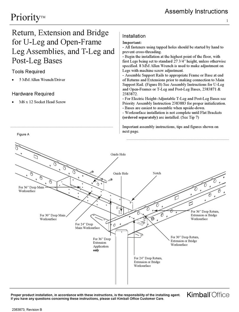
Note: A basic Screen Assembly consists of a Starter Screen
(2 casters) and an Add-on Screen (1 caster) as a minimum.
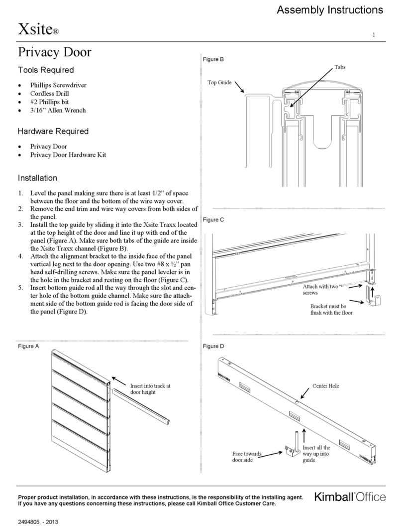
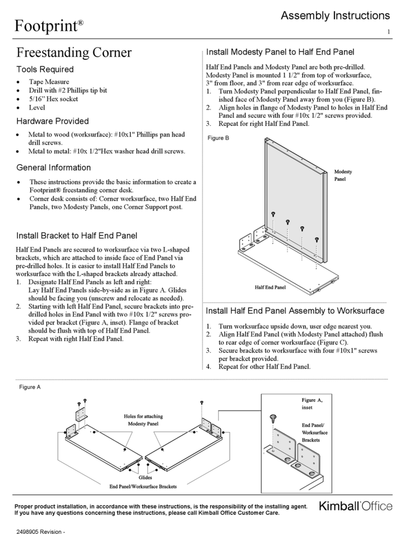
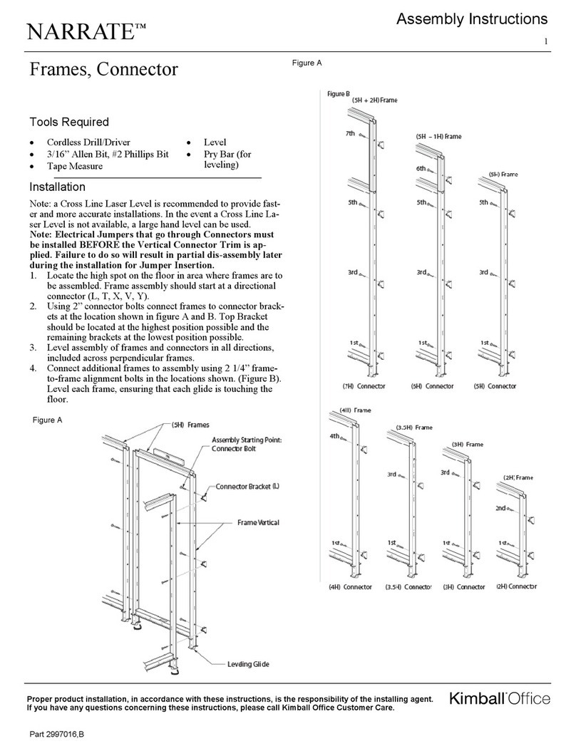
1. Plac a Start r Scr n and an Add-On Scr n sid by sid on
a cl an, solid surfac or floor; prot ct scr n tub s from
marks and scratch s. (Figur A).
2. Plac th two s ctions of th handcuff around th adjac nt
top collars at th top of th scr n tub s and fast n tog th r
with th handcuff scr w as shown. (Figur B). R p at
proc dur for low r conn cting collars locat d abov th
cast rs.
Note: Additional Add-On Screens may be attached to the basic
assembly by repeating Step 2.
Note: O er-tightening of the handcuff screws may constrain
the folding capability of the mobile screens.
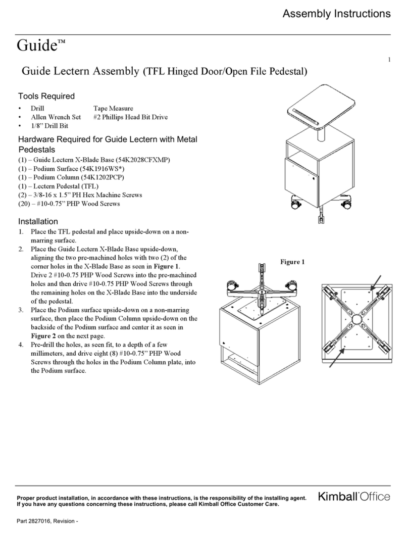
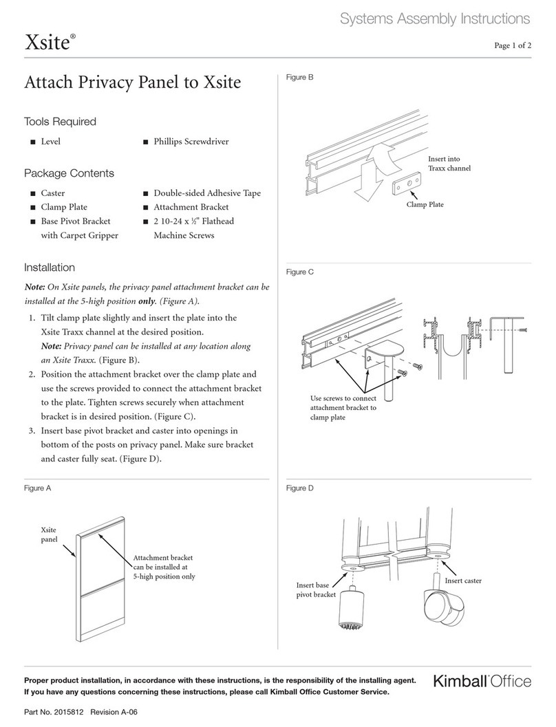
3. Ins rt cast rs into sock ts in th bottom of th scr n tub s.
Mak sur cast r fully s ats in sock t. If n c ssary, us a
rubb r mall t to s at cast r. DO NOT strik cast r with any
oth r hard obj ct. (Figur C).
Note: Each Starter Screen must ha e 2 casters inserted.
Use 1 caster with each add-on screen. There should be only
one caster at each screen connection.
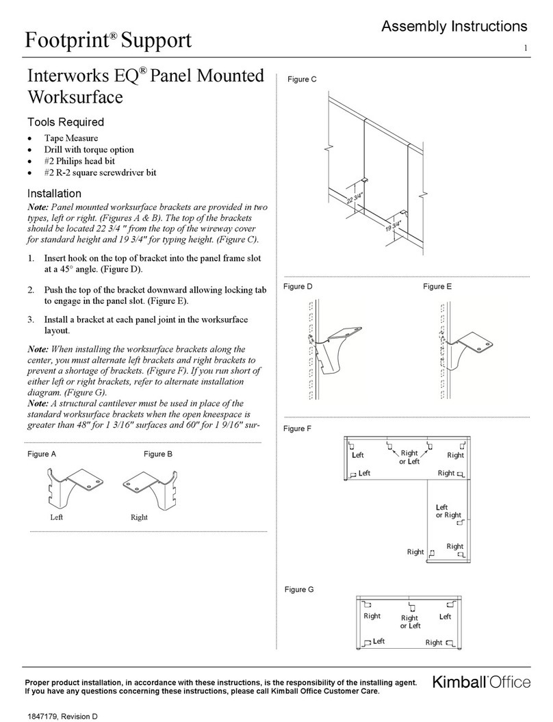
4. Stand ass mbl d unit upright. For saf ty and stability, mak
sur position of scr ns do s not xc d 115˚. (Figur D).
Figure A
Figure B
Start r Scr n
Handcuff Scr w
(suppli d)
Do Not Ov r-Tight n
Add-on Scr n
P inted in U.S.A. © 2010 Kimball Inte national, Inc. T 800.482.1818 F 812.482.8300
Figure C
Figure D
No mor
than 115°
Scr n
Conn cting
Collars
Top of scr n
Handcuff
s ction
Handcuff
s ction
1 cast r on ach
Add-on Scr n
2 cast rs on
Start r Scr n
1 cast r only
at ach scr n
conn ction
