Kitvision rush hd100W User manual

1 1
kitvision.co.uk
JB. 2776 © Kitvision™2013 Christchurch, Dorset. BH23 4FL
Action cAmerA
HD100W
User manual

2 3
With a wide range of cameras and accessories, Kitvision is here to help you record your memories.
We’re committed to developing the very latest technologies so you can capture, re-live and share
your experiences in the best way possible. By remembering the past and embracing the future,
our vision is for every single precious moment to be treasured forever.

4 5
Contents
Main features 6
Box contents 7
Functions 8
Using the camera 10
Using Wi-Fi 15
Connecting your camera 18
Before mounting your camera 20
Mounting your camera 22
Troubleshooting 36
Specifications 37

6 7
Box contents
Carefully unpack the box and ensure that you have the following accessories:
1. Body Piece with 2 Screw and Nut Sets
2. Tilting Head Adaptor
3. Helmet Strap with Clip (15") x 2
4. Curved Base with 3M Adhesive
5. Mini USB Cable
6. Strap Wings with Flat Eva Pad x 2
7. Grip Wings with Curved Rubber Pad x 2
8. Flat Wings with 3M adhesive x 2
9. 90°Adaptor
10. Secure Piece for Board (surf/skate)
11. Quick Release Adaptor key
12. Grip Tie x 2
13. Quick Release Adaptor with Socket
14. Secure String
15. Neoprene Case
16. Carabiner
17. User Manual
Main features
• Records1080pFullHDvideousingoneeasyslideswitch
• Takes5MPdigitalphotographs
• Supportsupto32GBMicroSDcardsandtakesFHDvideosupto4hours
• Built-in1200mAhLi-Polymerbatteryforupto2.5hoursofcontinuoususe
• Waterproofupto10metreswithoutusingextracasing
• Transfer files to your PC or mobile device wirelessly. Also turns your smart phone to a viewfinder and a remote control 1
5
9
14
2
6
10
15
4
8
13
17
3
7
1211
16
1
Action cAmerA
HD100W
Usermanual

8 9
1
4
2 3
Functions
1. Power/Shutter button •Turnsthecameraonoroff
•Takesasinglephotograph
2. LEDindicator Shows the camera status
3. Recording slide switch Slide to start or stop video recording
4. Lens High quality lens
5. MicroSDcardslot MicroSDcardstoragelocation
6. MiniHDMIport ConnectsthecameratoaTVviatheHDMIcable
7. USB port •Connecttoacomputerfordatatransferorcamerasetup
•Chargesyourcamera
8. Video resolution switch Selectsvideoresolution:FHD(FullHD)orHD
9. Reset button Resets the camera
10. Wi-FiLEDindicator Shows the Wi-Fi status
11. Wi-Fi power button (located on the camera body) Turns the Wi-Fi on or off
12. Back cover Rotates to seal the camera
13. Wi-Fi power button (located on the back cover) Turns the Wi-Fi on or off
5
6
89
12
13
7
10 11

10 11
Using the camera
Charging
ChargeyourcamerawiththeUSBcableviaaPCorUSBadaptor(notincluded).TheredLEDlightsuptoindicatethatthe
cameraischarginganditwillturnoffassoonasthecamerahasbeenfullycharged.Ittakesabout3hourstofullycharge
the camera.
Inserting a memory card
InsertamicroSDcard(notincluded)beforeusingthecamera.EnsurethatthecamerapoweristurnedOFFbefore
inserting the card into the slot.
Note:ThereisonlyonecorrectdirectiontoinsertthemicroSDcardintotheslot.
DonotforcethecardintothecardslotasitmaydamageboththecameraandthemicroSDcard.
Note:AnewmicroSDcardshouldbeformattedbeforeuse.
For more information, please see ‘Connecting your camera’, page 18
Setting date and time
You can set the camera’s clock with the software to ensure that your video and photo files are saved with the correct
date/time information.
To set up the camera clock
1. ConnectyourcameratoacomputerwiththeUSBcable.Runactionplus.exeinyourmicroSDcardfolder(PConly).
2. Findthe‘DateandTime’andclick‘SET’.
3. Adjust the date and time or click ‘Sync with PC’ to set with your PC clock.
4. Click‘OK’tosavethesettings.
5. After completing the setting, disconnect the camera from the PC immediately to ensure that the date and time
are set correctly.

12 13
Sealing your camera
The waterproof housing allows the camera to be used up to 10 metres under water. You must seal the
camera with the back cover in order to protect the camera when using it in wet or damp conditions.
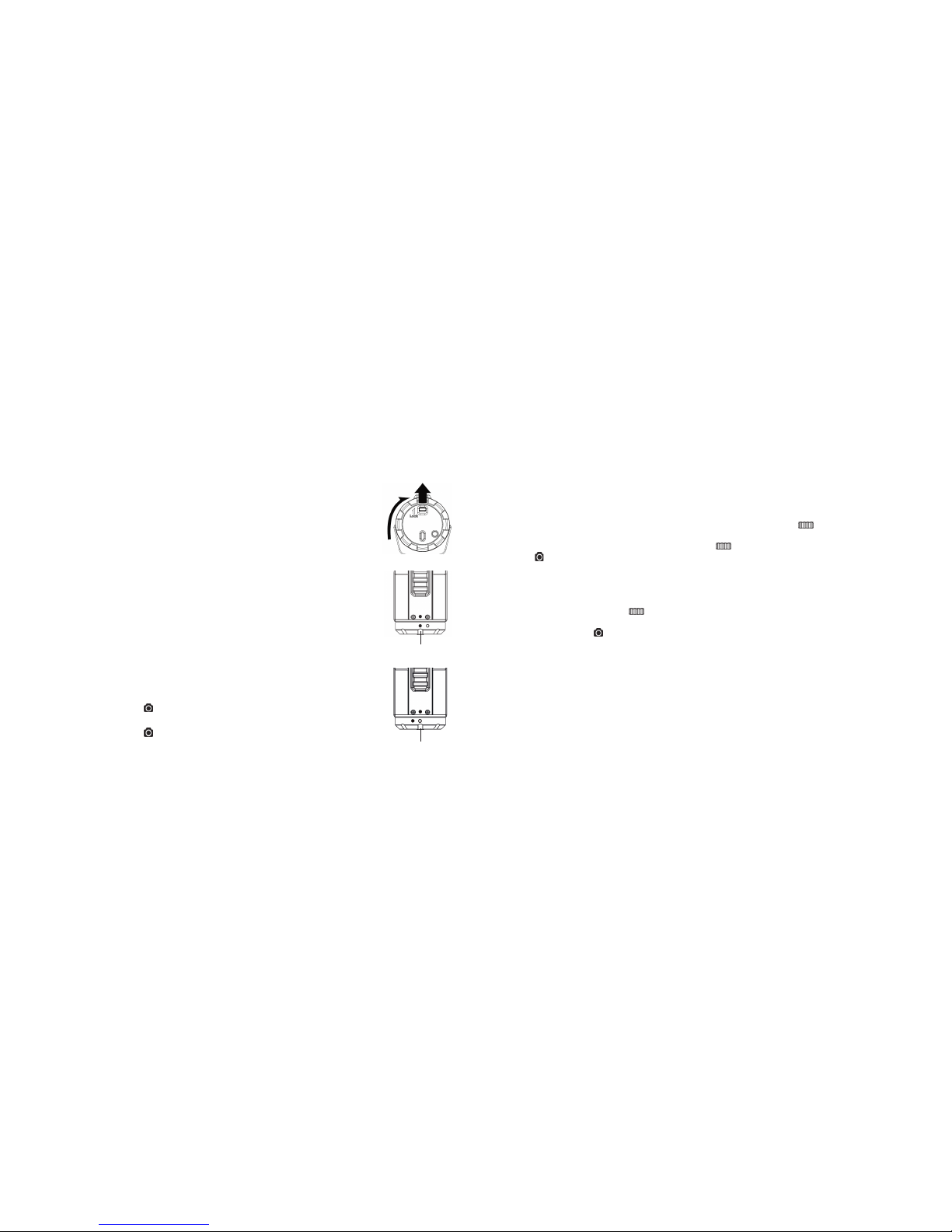
To secure the back cover
• Attachthebackcovertothebackofthecameraandrotateclockwiseuntilthetwoblackdots
are aligned
• Slidethelatchonthebackcovertolockit
• Toopen,slidethelatchonthebackcovertoloosenit.Rotatethecoveranticlockwiseuntilthewhiteand
black dots are aligned
Note: Failure to properly seal your camera can result in leaks that damage or destroy your camera.
Note: The rubber seal on the back cover forms the waterproof barrier to protect the camera in wet
and underwater conditions. You must keep this seal clean, as a single strand of hair or grain of
sand can cause a leak.
Note: After each use in salt water, you will need to rinse the outside of the product and the seal with
clean, salt-free water, and dry. Not doing this can cause corrosion of the product or failure
in the seal which in turn could damage the product.
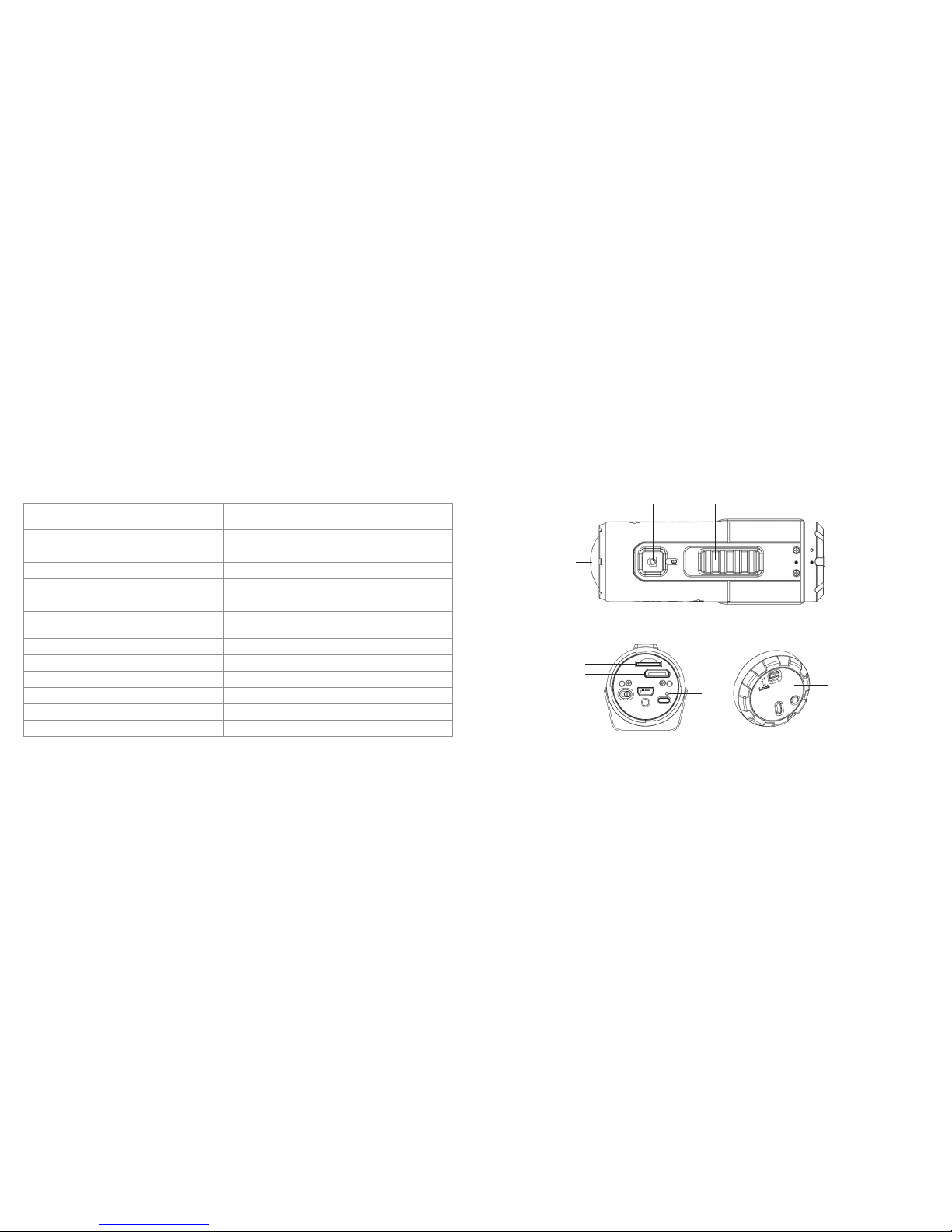
Turning the power on and off
To power ON the camera:
Press and hold the ‘Power’ button .ThecamerawillvibrateandthegreenLEDwillturnon.
To power OFF the camera:
Press and hold the ‘Power’ button .ThecamerawillvibratefortwosecondsandthegreenLED
will turn off.
Record videos
Before you start recording, select the video resolution by switching the ‘Video Resolution Switch’
There are two methods available for starting the video record function:
• WhetherthecamerapowerisONorOFF,simplyslidethe‘RecordingSlideSwitch’ from‘STOP’to‘REC’
to start recording
• WhenyourcameraisOFFandthe‘RecordingSlideSwitch’ is in the ‘REC’ position, press and hold the ‘Power’
button toturnthecameraONanditwillstartrecording
Whenstartingavideorecording,ashortvibrationwillindicatethatrecordinghasstarted.TheLEDindicatorwillilluminate
REDthroughouttherecording.
There are two methods available for stopping the video record function:
• Movethe‘RecordingSlideSwitch’ from‘REC’to‘STOP’tostoprecording.ThecamerawillvibrateandtheLED
indicator will illuminate GREEN to indicate the recording has stopped. The camera will then enter standby mode
• Holdthe‘Power’button to stop the recording and turn the camera off. The camera will vibrate for two seconds
andtheredLEDlightwillturnoff
Note: An additional low-res video file with the file name ACTPXXXX_thm.mov (XXXX is 4 numeric digit) will be created
simultaneouslywiththerecordingofanHD/FHDvideole.Thesmallervideolesizeallowsformoreefcient
uploading of content to social media sites and email. The resolutions of the additional videos are 432x240 when
recording 1080p/720p and 320x240 when recording 960p.
Note: Changing the video resolution is disabled during video recording.
Note: There will be about a 1-2 second delay before the camera starts recording.
Note:ThevariousvideoresolutionoptionsforHDandFHDcanbechangedunderthe‘Settings’optioninthesoftware.
Note:EnsurethatthereissufcientmemoryavailableonthemicroSDcard.Ifthecardisfull,thecamerawillvibratefor
vesecondsandthegreenLEDwillashcontinuously.
Locked
Unlocked

14 15
Taking photos
1. Turn on the camera by pressing the ‘Power’ button .
2. Oncethecameraison,pressthe‘Power’button totakeaphoto.TheLEDwillashgreenandtherewillbeashort
vibration to indicate that the action was successful.
Note: The still photo function is disabled during video recording.
Note: The default photo mode is ‘Single Photo’. ‘Burst-Shot’ mode gives you 10 continuous photo shots to capture
thatunmissablemoment.‘TimeLapse’modecanbeutilizedtotakeaseriesofphotosat5,10,30or60-second
intervals. To change the mode, please refer to ‘Running the software’, page 19.
Note:Ifthecardisfull,thecamerawillvibrateforvesecondsandthegreenLEDwillashcontinuously.
Auto rotation
The camera has a built-in G-sensor that detects the camera orientation. By rotating your camera to 90°, 180°or 270°
from the default position (refer to the picture), the recorded view will be rotated to the same angle. This allows you to
mount the camera in different orientation without recording a rotated or inverted view. The video resolution will be
adjusted for 90°and 270°.
Note: This feature is available for capturing videos only, not still photos.
Note: Adjust your camera orientation before you start the video recording. The rotation feature will not be activated
during the recording.
Note: You can disable the auto rotation function under the ‘General Settings’ option in the software.
Using Wi-Fi
Turn on Wi-Fi
1. Press and hold the ‘Power’ button to turn on your camera.
2. Press the ‘Wi-Fi Power Button’ either on the camera body or on the back cover to turn on Wi-Fi. After a short vibration,
theblueLEDlightsuptoindicatethatWi-Fiispreparing.Itwilltakearound15-20secondsfortheWi-Fitobecome
readyandconnectable.TheLEDwillashwhentheWi-Fifunctionisactiveorconnected.
3. To turn off Wi-Fi, press the Wi-Fi power button either on the camera body or on the back cover. The camera will vibrate
and Wi-Fi will turn off.
Note: Wi-Fi will drain the camera battery more rapidly when activated. Turn Wi-Fi off if you are not using it to change
settings or upload content.
Connecting the camera to your computer
1. Turn on Wi-Fi.
2. GotoyourPC’sorMac’snetworksettingsandchooseWi-Fi.Searchthenetworkandndandclick‘ACTIONPLUS’.
3. Enter the password ‘123456789’ to connect to your camera.
4. OpenyourInternetbrowserandinput‘192.168.1.2’or‘action.plus’.Youcanthenviewthelesstoredonyourcamera.
Connect the camera to your smart device (browser)
1. Turn on Wi-Fi.
2. Gotoyourmobiledevice’snetworksettingsandchooseWi-Fi.Searchthenetworkandndandclick‘ACTIONPLUS’.
3. Enter the password ‘123456789’ to connect to your camera.
4. OpenyourInternetbrowserandinput‘192.168.1.2’or‘action.plus’.Youcanthenviewthelesstoredonyourcamera.
Video resolution 0° or 180° 90° or 270°
1080p 1920 x 1080 608 x 1080
960p 1280 x 960 720 x 960
720p 1280 x 720 416 x 720

16 17
Viewing files from Internet browsers via Wi-Fi
1. Follow steps 1-4 in the section ‘Connecting the camera to your computer’, on page 15 of this user manual.
•Inthenavigationpage,clicktheSettingicon
•KeyinyournewSSIDandkeyineachblankaccordingly
•ClicktheSubmiticontosubmityoursetting
•ClicktheRebooticonforthechangestotakeeffect
•AfterresettingtheSSIDandkey,youshouldreconnectWi-Fi
2. Inthenavigationpage,clicktheLiveStreamingicontoconductreal-timemonitoring.
3. Inthenavigationpage,clicktheUpdateicontoupgradethermwaretoanewversion(ifavailable).
4. Beforecompletingarmwareupdate,makesureyouhaveinsertedamicroSDcardwiththeupdatedrmwareleon
it into the camera.
•Inthenavigationpage,clicktheUpdateicon
•’Pleaseclickhere’willshowonthewebpage.Clicktheword‘here’tostartupdating.TheWi-FiLEDindicatorwillstay
on for about one minute and will turn off once the update is complete
Connecting the camera to your smart device (App)
1. Search for the Action+ app in your device’s relevant App store.
2. Downloadandinstalltheapptoyoursmartdevice.
3. Turn on Wi-Fi.
4. Gotoyourmobiledevice’snetworksettingsandchooseWi-Fi.Searchthenetworkandndandclick‘ACTIONPLUS’.
5. Enter the password ‘123456789’ to connect to your camera.
6. OpenyourappandfollowApp-specicinstructions.
Brief introduction of our App:
TheAction+App(File)allowsyoutobrowsethelessavedinyourcameraandviewthephotosandvideosonyouriOSor
Android mobile device. You can download the photos and videos to your smart device, select the file(s) you would like to
share on social media sites or upload files to the Cloud.
TheAction+App(Remote)offersyoufullcontrolofthecamerawirelesslyusingyouriOSorAndriodmobiledevice.You
can use all camera settings, start and stop video recording, take photos via your smart device or use the smart device as a
viewfinder to preview during recording (live steaming).
Note: When the camera starts video recording, the live streaming, file play back and transfer functions will be temporarily
disabled. Functions will resume when your camera is in standby status.

18 19
Connecting your camera
Connecting your camera to a PC via USB
The unit can be connected to a computer as a mass storage device to transfer photo/video files for storage.
1. Connect your camera to a PC via the USB cable included
2. Press the ‘Power’ button to turn the camera on.
When the camera is connected to the computer as a mass storage device, you can:
• OpenthemicroSDfolderandbrowsethelessavedinthecamera
• FormatthemicroSDcard
Note:Ifyoucannotndthedevice,unplugthecablefromthePC,turnthecameraonandoffonceand
reconnect to the PC.
Running the software
1. InsertamicroSDcardwithatleast2MBoffreespaceintoyourcamera.
2. Connect your camera to a PC via the USB cable included.
3. Press the ‘Power’ button to turn the camera on.
4. OpenthemicroSDcardfolderinsidelemanagerandyouwillndthele“actionplus.exe”.Clickontheletoopenit
(PC only).
Ifyoucannotndactionplus.exeinyourmicroSDfolder,unplugthecablefromthePC,turnthecameraonandoffonce
and reconnect to the PC.
Using the software, you can:
• Changethephotosetting–photoresolutionandmode
• Changethevideosetting–FHDandHDresolution
• Changethecamera’sgeneralsettings–TVtype,language,autopoweroff,autorotation,dateandtime
Connecting your camera to a TV/HDTV
YoucanconnectyourcameratoaTVorHDTVviatheHDMIcable(notincluded).Onceyouareconnectedyoucan:
• TakephotosorvideosbyusingyourTVasaviewnder
• Playbackallphotoandvideolessavedinthecamera
• Deletelessavedinthecamera
• FormatthemicroSDCard

20 21
Before mounting your camera
Securing the strap
The secure strap can provide additional security for your mount once you have installed the camera onto the mount.
• Looponeendofthesecurestrapthroughthestrapholeofthecameraandouttheback,usingapintohelpthread
it through the hole if needed
• AttachtheotherhalftotheSecurePieceorholeintheFlatWings,StrapWingsorGripWings
• OncethecamerahasbeensecuredtotheFlatMount,StrapMountorGripMount,clipbothendstogether
Attaching the Tilting Head Adaptor to your camera
1. Fit the screw of the Tilting Head Adaptor to the tripod socket of the camera.
2. Screw the Tilting Head Adaptor until it is tight.
Attaching the Quick Release Adaptor with socket to your camera
3. Fit the screw of the Quick Release Adaptor to the tripod socket of the camera.
4. Screw the Quick Release Adaptor until it is tight.
5. InserttheQuickReleaseAdaptorintotheQuickReleaseAdaptorsocket.
1
2
3
4

22 23
• AttachingthecameratotheBodyPieceviatheTiltingHeadAdaptor(fordetailsonhowtoattachtheTiltingHead
Adaptor to your camera, please refer to ‘Attaching the Tilting Head Adaptor to your camera’, page 21).
Note:Thecamerapositioncanbeadjustedhorizontally,plusthecameraanglecanberotatedupwardsordownwards
by loosening or tightening the nut on the Tilting Head Adaptor.
• AttachingthecameratotheBodyPieceviatheQuickReleaseAdaptorandQuickReleaseAdaptorsocket(fordetails
on how to attach the Quick Release Adaptor with socket to your camera, please refer to ‘Attaching the Quick Release
Adaptor with socket to your camera’, page 21).
Note:Thecamerapositioncanbeadjustedhorizontallywhenusingthismethod.
• AttachingthecameradirectlytotheBodyPiece.
Note:Thehorizontalandverticalpositionofthecamerawillbexedwhenusingthismethod.[continued...]
Mounting your camera
Mounting onto your board
Assembling the Flat Mount
• AttachtheFlatWingstotheleftandrightsideoftheBodyPieceaccordingly
Note: Please make sure you install the Flat Wings with the 3M adhesive facing downward and fit the gears of the
Flat Wings and the Body Piece correctly on both sides.
• Inserttheboltsthroughtheholesandtightenthenut
Note: The angle of the Flat Wings can be adjusted: simply loosen the nut, adjust the Flat Wings and re-tighten the nut.
Mounting onto your board
1. Peel off the 3M adhesive’s protective film on the left and right Flat Wings and attach the Flat Mount onto the board.
2. There are three ways to mount the camera onto the Body Piece:
Either use the Tilting Head Adaptor or Quick Release Adaptor socket to mount your camera onto the Body Piece or
attach your camera directly onto the Body Piece. Please note that the Tilting Head Adaptor provides a wider angle
to allow for greater adjustment
Rotate the nut

24 25
[...continued] Mounting onto your board
3. Rotate the wheel on the Body Piece anticlockwise to tighten the Tilting Head Adaptor, Quick Release Adaptor socket or
the camera itself onto the Body Piece.
4. Use the secure strap to link up the camera and secure piece of Flat Mount. To fasten the mount, please refer to
‘Securing the strap’, page 20.
5. Peel off the protective film which covers the double-sided adhesive on the secure piece and attach the secure piece
to a suitable location on the board.
Note: When mounting your camera with the Tilting Head Adaptor or Quick Release Adaptor socket, please make sure you
push the orientation column on the Body Piece down. When mounting your camera directly onto the Body Piece,
please pull the orientation column on the Body Piece up.
Note:Ifyouwanttomakechangestothehorizontalpositionofthecamera,you can rotate the wheel on the Body Piece
clockwise, adjust the camera position, and rotate anticlockwise to re-tighten the mount.
Mounting onto your bike helmet/backpack
Assembling the Strap Mount
1. Attach the Strap Wings to the left and right side of the Body Piece accordingly.
Note:PleasemakesureyouinstalltheStrapWingswiththeatevapadfacingdownwardsandtthegearsofthe
Strap Wings and the Body Piece correctly on both sides.
2. Inserttheboltintothesliderailfromtheholeandtightenthenut.
Note: The angle of the Strap Wings can be adjusted: simply loosen the nut, adjust the Strap Wings and re-tighten the nut.
Mounting onto your bike helmet/backpack
1. LoopthestrapoftheStrapMountthroughoneventoftheStrapWingfromthetop.
Next, follow either of the below steps according to your mounting object:
•Ifyouwanttomountontoyourbikehelmet,loopthestrapthroughtheventof
the bike helmet and pull it out from the opposite helmet vent
•Ifyouwanttomountontoyourbackpack,loopthestrapthroughonesideofthe
backpack shoulder belt and back through the other side
2. LoopthestrapthroughtheoppositeventoftheStrapWingfromthebottom.
3. Loopthestrapthroughtheventoftheclipfromthebottom.[continued...]
Rotate the wheel

26 27
[...continued] Mounting onto your bike helmet/backpack
4. Fasten the strap and tighten the strap clip.
5. Repeat the above steps on the opposite end of the strap until the Strap Mount is firmly attached to the helmet.
6. There are three ways to mount the camera onto the Body Piece: Either use the Tilting Head Adaptor or Quick Release
Adaptor socket to mount your camera onto the Body Piece, or attach your camera directly onto the Body Piece.
•AttachingyourcameratotheBodyPieceviatheTiltingHeadAdaptor(fordetailsonhowtoattachtheTiltingHead
Adaptor to your camera, please refer to ‘Attaching the Tilting Head Adaptor to your camera’, page 21)
Note:Thecamerapositioncanbeadjustedhorizontally,plusthecameraanglecanberotatedupwardsordownwards
by loosening or tightening the nut on the Tilting Head Adaptor.
•AttachingyourcameratotheBodyPieceviatheQuickReleaseAdaptorandQuickReleaseAdaptorsocket(fordetails
on how to attach the Quick Release Adaptor with socket to your camera, please refer to ‘Attaching the Quick Release
Adaptor with socket to your camera’, page 21)
Note:Thecamerapositioncanbeadjustedhorizontallywhenusingthismethod.
•AttachingthecameradirectlyontotheBodyPiece
Note:Thehorizontalandverticalpositionofthecamerawillbexedwhenusingthismethod.
7. Rotate the wheel on the Body Piece anticlockwise to tighten the Tilting Head Adaptor, the Quick Release Adaptor
socket or the camera itself onto the Body Piece.
Notes: When mounting your camera with the Tilting Head Adaptor or the Quick Release Adaptor socket, please make sure
you push down the orientation column on the Body Piece. When mounting your camera directly onto the Body
Piece, please pull the orientation column up.
Notes:Ifyouwanttomakechangestothehorizontalpositionofthecamera,youcanrotatethewheelontheBodyPiece
clockwise, adjust the camera position, and rotate anticlockwise to re-tighten the mount.
Notes: You may want to use the secure strap to link up the camera with the hole in the Strap Wings to fasten the mount.
Please refer to ‘Securing the strap’, page 20.

28 29
•AttachingyourcameratotheBodyPieceviatheQuickReleaseAdaptorandQuickReleaseAdaptorsocket(fordetails
on how to attach the Quick Release Adaptor with socket to your camera, please refer to ‘Attaching the Quick Release
Adaptor with socket to your camera’, page 21)
Note:Thecamerapositioncanbeadjustedhorizontallywhenusingthismethod.
•AttachingthecameradirectlyontotheBodyPiece
Note:Thehorizontalandverticalpositionofthecamerawillbexedwhenusingthismethod.
4. Rotate the wheel on the Body Piece anticlockwise to tighten the Tilting Head Adaptor, the Quick Release Adaptor
socket or the camera itself onto the Body Piece.
Note: When mounting the camera with the Tilting Head Adaptor or the Quick Release Adaptor socket, please make sure
you push the orientation column on the Body Piece down. When mounting your camera directly onto the Body
Piece, please pull the orientation column up.
Note:Ifyouwanttomakechangestothehorizontalpositionofthecamera,youcanrotatethewheelontheBodyPiece
clockwise, adjust the camera position, and rotate anticlockwise to re-tighten the mount.
Note: You may want to use the secure strap to link up the camera with the hole in the Grip Wings to fasten the mount.
Please refer to ‘Securing the strap’, page 20.
Mounting onto your handlebars
Assembling the Grip Mount
1. Attach the Grip Wings to the left and right side of the Body Piece accordingly.
Note: Please make sure you install the Grip Wings with the curved rubber
pad facing downwards and fit the gears of the Grip Wings and the
Body Piece correctly on both sides.
2. Inserttheboltsthroughtheholesandtightenthenut.
Mounting onto your handlebars
1. Attach and clip the Grip Mount onto the handlebars by adjusting the nuts.
Note: The angle of the Grip Wings can be adjusted: simply loosen the nut,
adjust the Grip Wings and re-tighten the nut.
2. LooptheGripTiethroughtheventsoftheGripWings,loopbackthroughthe
vent of the tie clip, and tighten the Grip Tie.
Note: By pressing the latch on the Grip Tie, you can loosen it.
3. There are three ways to mount the camera onto the Body Piece: Either use the
Tilting Head Adaptor or Quick Release Adaptor socket to mount your camera
onto the Body Piece, or attach your camera directly onto the Body Piece.
•AttachingyourcameratotheBodyPieceviatheTiltingHeadAdaptor
(for details on how to attach the Tilting Head Adaptor to the camera,
please refer to ‘Attaching the Tilting Head Adaptor to your camera’, page 21)
Note:Thecamerapositioncanbeadjustedhorizontally,plusthecameraangle
can be rotated upwards or downwards by loosening or tightening the
nut on the Tilting Head Adaptor.

30 31
Mounting onto your motorcycle helmet
Assembling the Curved Mount
1. InstalltheBodyPieceintotheCurvedBase.
Note: Please make sure you fit the gears of the Curved Base and the Body Piece correctly on both sides.
2. Inserttheboltsthroughtheholesandtightenthenut.
You can also mount your camera onto the side of your motorcycle helmet by using a 90° Adaptor.
Mounting without the 90º Adaptor
There are three ways to mount the camera onto the Body Piece: Either use the Tilting Head Adaptor or Quick Release
Adaptor socket to mount your camera onto the Body Piece, or attach your camera directly onto the Body Piece. Please
note that the Tilting Head Adaptor provides a wider angle to allow for greater adjustment.
a. Attaching the camera to the Body Piece via the Tilting Head Adaptor (for details on how to attach the Tilting Head
Adaptor to your camera, please refer to ‘Attaching the Tilting Head Adaptor to your camera’, page 21)
Note:Thecamerapositioncanbeadjustedhorizontally,plusthecameraanglecanberotatedupwardsordownwardsby
loosening or tightening the nut on the Tilting Head Adaptor. [continued...]

32 33
[...continued] Mounting without the 90º Adaptor
b. Attaching the camera to the Body Piece via the Quick Release Adaptor and Quick Release Adaptor socket (for details
on how to attach the Quick Release Adaptor with socket to your camera, please refer to ‘Attaching the Quick Release
Adaptor with socket to your camera’, page 21).
Note:Thecamerapositioncanbeadjustedhorizontallywhenusingthismethod.
c. Attaching the camera directly to the Body Piece.
Note:Thehorizontalandverticalpositionofthecamerawillbexedwhenusingthismethod.
2. Rotate the wheel on the Body Piece anticlockwise to tighten the Tilting Head Adaptor, the Quick
Release Adaptor socket, or the camera itself onto the Body Piece.
3. Peel off the protective film which covers the 3M adhesive under the Curved Mount, and attach the
Curved Mount onto the Helmet.
Mounting with a 90º Adaptor
You can also mount the camera onto the side of a motorcycle helmet with the 90º Adaptor:
1. Fit the screw of the 90º Adaptor to the tripod socket of the camera.
2. Screw the nut of the 90º Adaptor until it is tight.
Attaching the Tilting Head Adaptor to the Camera with the 90º Adaptor
3. Fit the screw of the Tilting head Adaptor to the tripod socket of the 90º Adaptor.
4. Screw the Tilting Head Adaptor until it is tight.
Attaching the Quick Release Adaptor with socket to the camera with the 90º Adaptor
5. Fit the screw of the Quick Release Adaptor to the tripod socket of the 90º Adaptor.
6. Screw the Quick Release Adaptor until it is tight.
7.InserttheQuickReleaseAdaptorintotheQuickReleaseAdaptorsocket.
1
3
5
6
4
2

34 35
Mounting onto your motorcycle helmet
There are three ways to mount the camera with the 90º Adaptor onto the Body Piece: Either use the Tilting Head Adaptor
or the Quick Release Adaptor socket to mount your camera with the 90º Adaptor onto the Body Piece, or attach your
camera with the 90º Adaptor directly onto the Body Piece. Please note that the Tilting Head Adaptor provides a wider
angle to allow for greater adjustment.
a. Attaching the camera to the Body Piece via the Tilting Head Adaptor (for details, please refer to
the section ‘Attaching the Tilting Head Adaptor to the camera with the 90º Adaptor’, page 33)
Note:Thecamerapositioncanbeadjustedhorizontally,plusthecameraanglecanberotated
upwards or downwards by loosening or tightening the nut on the Tilting Head Adaptor.
Rotate the wheel
b. Attaching the camera with the 90º Adaptor to the Body Piece via the Quick Release Adaptor
and Quick Release Adaptor socket (for details, please refer to the section ‘Attaching the Quick
Release Adaptor with socket to the camera with the 90º Adaptor’, page 33).
Note:Thecamerapositioncanbeadjustedhorizontallywhenusingthismethod.
c. Attaching the camera with the 90º Adaptor directly to the Body Piece.
Note:Thehorizontalandverticalpositionofthecamerawillbexedwhenusingthismethod.
Note: Before mounting, make sure the surface of the helmet on which the 3M adhesive will be adhered is clean so that the
Curved Mount can be fixed onto the helmet securely.
Note: When mounting your camera with the Tilting Head Adaptor or the Quick Release Adaptor socket, please make sure
you push the orientation column on the Body Piece down. When mounting your camera directly onto the Body
Piece, please pull the orientation column up.
Note:Ifyouwanttomakechangestothehorizontalpositionofthecamera,youcanrotatethewheelontheBodyPiece
clockwise, adjust the camera position and rotate anticlockwise to re-tighten the mount.

36 37
Troubleshooting
Problem Cause Solution
LEDashesandcameraturnsoff Batteryisat Recharge the battery
Camera cannot be turned on Batteryisat Recharge the battery
RedLEDashesduringrecording Lowbattery Recharge the battery
Cannot take photos or video
(greenLEDashes) Memory full Replace with an empty memory card
Cannot take photos or video
(greenandredLEDashesalternatively)
MicroSDcardisnotinserted InsertmicroSDcard
MicroSDcardhasnotbeen
formatted properly FormatthemicroSDcardusingaPC
Cannot find removable disk after
connecting the camera to the computer Connection failure
Make sure all cable connections are secured
and restart the computer if necessary
Try a different USB port
Specifications
Sensor 5megapixelCMOSsensor
Lens 170º ultra wide angle field of view
Focus range 0.5m–∞
Video
1080p: 1920 x 1080 pixels (16:9), 30 FPS
960p*: 1280 x 960 pixels (4:3), 30 FPS
720p: 1280 x 720 pixels (16:9), 60 FPS
720p*: 1280 x 720 pixels (16:9), 30 FPS
Format: H.264 compression, saved as MPEG4 (.mov) file**
Dualvideolesforeasysharing
Photo Resolution: 5 megapixel in JPEG format
Capturemodes:SinglePhoto,Burst-Shot*,TimeLapse*
Audio Built-in high quality microphone
ADPCMCompression,AutomaticGainControl
Storage MicroSD/microSDHCwithminimumclass6upto32GB(notincluded)
Averagerecordingtimes:about4hours(using32GBmSDcardin1080p30/720p60)
Connection
USB 2.0 (for data connection and battery charging)
HDMI
Wi-Fi (802.11 b/g/n)
Power Built-in1200mAHrechargeableLi-Polymerbattery
Battery life: Approx. 2.5 hrs (w/o Wi-Fi) or 1 hr (w/ Wi-Fi)
Housing High quality finish
Waterproof up to a depth of 10 metres
Unitsize 108.1 x 39.3 x 40.7 (mm)
Weight 134.4 g
*Settings can be changed through software settings.
**Ifyoucannotplaytheleformatonyourexistingmediaplayer,pleasedownloadQuickTimePlayerandtryagain.

38 39
Important
•Keepthelensclean.Dirtandngerprintswillaffectthequalityofthepicture
•Closethebackcoverproperlytoensurebestwatersealing.Donotopenitunderwater
•Rinsethecamerawithcleanwaterafteruseandkeepitdryduringstorage
•Youcanrefertothedetailedoperatinginstructionsinthisusermanual
FCC Statement
Caution Statement
“Modicationsnotapprovedbythepartyresponsibleforcompliancecouldvoidtheuser’sauthoritytooperatetheequipment.”
Instruction Statement
NOTE:ThisequipmenthasbeentestedandfoundtocomplywiththelimitsforaClassBdigitaldevice,pursuanttoPart15
of the FCC Rules. These limits are designed to provide reasonable protection against harmful interference in a
residential installation. This equipment generates, uses and can radiate radio frequency energy and, if not installed
and used in accordance with the instructions, may cause harmful interference to radio or television reception,
which can be determined by turning the equipment off and on, the user is encouraged to try to correct the
interference by one or more of the following measures:
•Reorientorrelocatethereceivingantenna
•Increasetheseparationbetweentheequipmentandreceiver
•Connecttheequipmentintoanoutletonacircuitdifferentfromthattowhichthereceiverisconnected
•Consultthedealeroranexperiencedradio/TVtechnicianforhelp
WARNING:THEMANUFACTURERISNOTRESPONSIBLEFORANYRADIOORTVINTERFERENCECAUSEDBY
UNAUTHORIZEDMODIFICATIONSTOTHEDEVICE.ANYSUCHMODIFICATIONSCOULDVOIDTHEUSER’SAUTHORITY
TOOPERATETHEEQUIPMENT.
System requirements
Trademark information
Microsoft® and Windows® are U.S. registered trademarks of Microsoft Corporation.
•Pentium®isaregisteredtrademarkofIntelCorporation
•iPhone,iPad,MacintoshisatrademarkofAppleInc
•SD,SDHC,microSDHClogosaretrademarksofSD-3C,LLC
•Othernamesandproductsmaybetrademarksorregisteredtrademarksoftheirrespectiveowners
Operatingsystem Windows 7/XP SP3 /Vista and Mac 10.5 or above
Interface USB port
Table of contents
Other Kitvision Action Camera manuals

Kitvision
Kitvision explore 1080p User manual

Kitvision
Kitvision ESCAPE 4KW User manual

Kitvision
Kitvision Venture User manual

Kitvision
Kitvision edge HD30W User manual

Kitvision
Kitvision Escape HD5W User manual

Kitvision
Kitvision ESCAPE 4KW User manual

Kitvision
Kitvision Edge HD10 User manual

Kitvision
Kitvision rush User manual

Kitvision
Kitvision escape User manual

Kitvision
Kitvision blast User manual