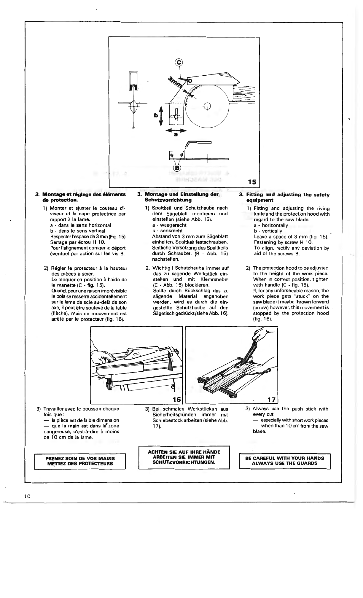
Kity 10 0618 User guide

.-
N
0
.-
LO
~
Q)
"O
0
Notice
d'
entretien
etd'
utilisation
Wartunps-
und
Betriebsanleitung
Instructions
for
maintenance
and
use
---------
-
----
--
scie
circulaire
10
0618
tischkreissBge
circular
saw
U
'---
- -
--
---
-
---,-----
- ~ -
-___J
1
/2
/5 K 8601 Z

2
1.
CARACTÉRISTIQUES
TECHNIQUES
Table-machine
Surface de travail
520
x
680
mm
avec rallonges
920
x
680
mm
Hauteur
au
sol
(machine sur caisson support)
850
mm
Lame
de
scie
(/J
maximum
Alésage
Hauteur
de
coupe
a/lame
CP.
250
mm
a
/lam
e
(/)
200
mm
réglable (course)
Lame inclinable
Vitesse
en T
/mn
Capacité
de
coupe
a/guide paralèlle
Guide
d'angle
250
mm
(/J
30
mm
28
à
85
mm
3 à
60
mm
57
mm
0 .
45°
4100
jusqu'à
700
mm
(avec r.allonges).
45°.
0.
45°
Poids (avec caisson support)
65
kg
Moteur
mono
ou
tri
1.5
kW
(2
CV)
3000
T/
mn
Emission
phonique
L'émission
phonique
au lieu de
travail
déterminé
selon OIN 45635 est :
à
vide:
80
dB
(A)
en charge: 86,3
dB
(A)
1.
TECHNISCHE
DATEN
Maschinentisch
Abmessung
520
x
680
mm
920x680mm
850
mm
Mit
Tischverbreiterung
Arbeitshôhe
mit
Unterbau
Siigebliitter
(/J
maximum
Bohrung
Schnitthohe
250
mm
30
mm
Sageblatt
(/>
250
mm
von
28
bis
85
mm
Sageblatt
</)
200
mm
von 3 bis
60
mm
Hôhenverstellung 57
mm
Schwenkung des Blattes O -
45
°
Drehzahl
U/min.
4100
Schnittbreite
zwischen Anschlag und Sageblatt
mit
Tischverbreiterung
700
mm
Gehrungsanschlag
schwenkbar
Gewicht
mit
Unterbau
45°
- 0 -
45°
65
kg
Motorleistung
Abgabe
1,5
kW(2
PS)
Drehzahl
Motor
3000
U/min
.
Geraüschemission
Der
nach OIN 45635 gemessene arbeits-
platzbezogene
Emissionswert
betriigt
:
im
Leerlauf:
80
dB
(A)
bei
Bearbeitung:
86,3
dB
(A)
1.
TECHNICAL
DATA
Machine
table
Working
surface
with
table extensions
Height
on
floor
stand
Circula,
saw
blade
Maximum
dia (U. K.)
Maximum dia
Bore dia.
Cutting
depth
520
x
680
mm
920x680mm
850
mm
270
mm
250
mm
30
mm
with
blade dia.
270
mm
=
38
-
95
mm
with
blade dia.
250
mm
=
28
-
85
mm
with
blade dia.
200
mm
= 3 -
60
mm
Depth range 57
mm
Hand
wheel
tilt
O -
45°
Cutting
speed
r.
p. m.
4100
Cutting
capacity
with
parallel fence up
to
700
mm
(with
table extensions)
Mitre
guide
45°
- 0 -
45°
Weight
(with
floor
stand)
65
kgs
Single phase
motor
1,5
kW
(2
h.p.)
3000
r.p. m.
Three phase
motor
1,5
kW
(2
h.p.)
3000
r.
p.
m.
Sound
emission
Sound
emission,
the
work
place
determined
as
par
Dl
N 45635
is
:
at
Free
turning:
80
dB
(A)
in
work:
86,3
dB
(A)
UTILISATION
DES
LAMES
DE
SCIE
BENUTZUNG DER SAGEBL~TTER
CIRCULAR
SAW
BLADES APPLICATION CHART
Dessins
Références
30 4106 006
30 4132 006
30 4108 006
304107 006
30 4109 006
Dimensions
0 250 X 2,7 X 24
(carbure)
0 250 X 3 X
24
(carbure)
0 200 X 3 X 12
(carbure)
0 250 X 2,8 X
52
(carbure)
0 250 dent. 10
(80 dents)
(Chrome
-Nickel)
ou vanadium)
Utilisation
- à denture alternée, spéciale "délignage"
excellente qualit~ de coupe
-
pour
coupes
en
travers
et
délignage,
spéciale
"Bois"
-
Rainurage
-
Travaux
courants
pour
hauteur
de coupe
de
3 à 60
mm
- à dents traceuses
et
dégorgeuses
-
Super
pour
lamifiés, stratifiés, ...
Tous
travaux
courants
de
sciage

SOMMAIRE
INHALTSVERZEICHNIS
CONTENTS
1. Caractéristiquestechniques 2 1. Tachnische
Daten
2
1.
Tachnical
data
2
Utilisation des lames
de
scie 2 Anwendung der Sâgeblâtter. 3 Circularsawbladesapplicat. chart 3
2. Description 2. Beschreibung 2. Descril)\ion
1.
Scie circulaire d·établi 4
1.
Tischkreissâge_ 4
1.
Basic machine 4
2.
Accessoires 4
2.
Zubehèir 4
2.
Accessories 4
2.
1.
Le
caisson-support 4
2.
1. Unterbauschrank 4
2.
1. Floor stand 4
2.
2.
Ensemble
rallonges
de
table 5
2. 2.
Tischverbreiterung 5
2. 2.
Set of table extensions 5
2.
3.
Chariot
de
sciage 5
2.
3. Schiebeschlitten 5
2.
3.
Saw carriage 5
3. Partie électrique 3. Elektrischer Anschluss 3. Elactrical section
1. Branchement 7 1. Anschluss allgemein 7 1. Connection 7
1. 1. Monophasé 7 1. 1. Wechselstrom 7 1. 1. Single phase 7
1. 2. Triphasé 7 1.
2.
Drehstrom 7 1. 2. Three phase 7
2. .Schémas 8
2.
Schaltplan 8
2.
Diagrams 8
4.
Mise
en route
4.
lnbetriebnahme 4. Starting
1. Montage-démont.
de
la
lame 9 1. Montage des Sâgeblattes 9 1. Mount. and remov. the blade 9
2.
Réglage
de
la
hauteur
decoupe 9
2.
Hôhenverstellung 9
2.
Adjusting the cutting depth 9
3.
Montage et réglage des éléments
3.
Montage und einstellen der
3.
Fitting and adjusting the safety
de
protection
10
Schutzvorrichtung
10
equipment
10
5. Utilisation
de
la machine 5.
Anwendung
der
Maschine 5. Using
the
machine
1. Coupe parallèle 11
1.
Einstel.
des
Langsanschlages
11
1.
Parallel cuts
11
2.
Coupe
en
biais
12
2. Einstel.
für
Schriigschnitte
12
2.
Angle cutting
12
3. Coupe d'onglet
13
3.
Winkelschnitte
13
3.
Mitre guide
13
6. Propreté
et
entretien
de
votre 6.
Wartung
und Pflege
14
6. Cleaning and maintenance
of
machine
14
your machine
14
7. Sécurité
14
7. Sicherheit
14
7.
Safety
14
a
AnomaliesdefoilCtÎOl
■
iement
15
8. Betriebsstorungen
15
S.
Faults in performance
15
Attestation
de
conformité
16
Bezeichnung
Utilisation
Wechselzahn
hëchste
Standzeit.
Niedrige
Vorschubkraft
-
for
all
standard
jobs,
ripping,
cross
cuts
or
fine
speziell
nëtig
zum
Zuschneiden
work
as
above
Ref. 30 4110 006
(U.
K.) =270 x 2,7 x 24
zum
Zuschneiden
und
Querschneiden
speziell
von
-
special
rip
blade
"Wood"
Naturhëlzer
Wechselzahn
hôchste
Standzeit.
Niedrige
Vorschubkraft
-
grooving
nôtig
zumZuschneiden undQuerschneiden
von
Naturhôlzer, -sta.
ndard
jobs
from
3 -
60
mm
Spanplatten,
Tischlerplatten,
Gipsplatten,
Sperrholz.
1 '
Hohl
+Trapezzahn.
Standzeit
3 x
hôher
ais
gewôhnlich
. -",Trace"
teeth
-
excellent
for
laminated
wood
H.
M.
Blatter
Gerauscharm. Durch
neuartige
Zahnschneid-
geometrie
optimale
Schnittgüte
an
den
Kanten
von
ein-
seitig
und
beidseitig
beschichteten
Plattenwerkstoffe.
Zum
Sagen Naturhôlzer,
Tischlerplatten,
Sperrholz. -all
standard
jobs
Ref.
30
4111
006
(U.K.) =
270/-1
O.
3

4
2. DESCRIPTION
1. Scie circulaire d'établi
(sans le caisson-support)
La
machine standard comprend :
A • Elément de base
B • Guide parallèle
C • Guide d'angle
D • Poussoir
E • Lame de scie
F • Clés de service
G • Broche d'arrêt
2. ACCESSOIRES
2.
1.
Le caisson-support
li
comprend:
A -
Ca
isson
B - Porte de visite
C - 2 patins réglables
D - Roulettes
E - Sachet visserie
Montage:
Monter
dans l'ordre :
- les roulettes
(D
-fig. 2)
-les patins
(C
-fig. 2)
Poser la machine orientée suivant fig. 2
sur le caisson et fixer
su
ivant flèches
après avoir retiré les deux portes latérales.
2. BESCHREIBUNG
1.
Tischkreissige
(ohne Unterbauschrank)
Standardmaschine bestehend
aus
:
A • Tischkreissiige
B • Liingsanschlag
C • Gehrungsanschlag
D • Schiebestock
E · '
Siigeblatt
F • Montage • Werkzeug
G • Arretierstift für Siigeblattwechsel
2. ZUBEHÔR
2.
1.
Unterbauschrank
Unterbauschrank bestehend
aus
:
A - Gehiiuse
B - Schranktüre
C - 2 verstellbare Füsse
D - Rollenvorrichtung
E - Montageschrauben
Montage:
Richtige Reihenfolge beachten :
-Rollenvorrichtung
(D
-Abb. 2)
-Verstellfüsse
(C
-Abb. 2)
Maschinenach
(A
-Abb. 2) in Pfeilrichtung
aufden Unterbau setzen undfestschrauben.
2. DESCRIPTION
1. Circular
saw
(Machine wi
thout
floor stand)
Machine supplied
as
standard
with
:
A - Basic machine
B • Parallel fence
C - Mitre guide
D -
Push
sti
ck
E • Saw blade
F - 2 spanners
G - Stop rod
2
2. ACCESSORIES
2. 1. Floor stand
lncluding :
A - Casing
B - Door
C -
Two
adjustable feet
D - Rollers (optional extra)
· E - Fixing screws
Assembly:
Assembly
as
follows :
-the rollers
(D
-fig. 2)
-the skids
(C
-fig. 2)
Position the machine
as
in fig. 2
on
the
floorcasing and fix following arrows after
having removed the
two
side doors.

2.
2.
Ensemble rallonges
de
table
Comprend:
A • 2 tablettes largeur
200
mm
B • 1 glissière avant
C • 1 glissière arrière
D • 1 butée de guide
E • 1 profil guide parallèle
F • 1 sachet visserie
Les
tablettes se montent de part et
d'autre. ou à droite
de
la
lame suivantfig.
4.
•
--
-------
2.
3.
Chariot
de
sciage
Comprend:
A - Tablette
B - Guide orientable
C • Profil guide réglable
D • Butée de longueur
E - Ensemble glissières
F • Pied
G • 2 bras de fixation à
la
machine
H • Elément de serrage
1- Visserie
K • Butée amovible de mise à 0
L • Bouton de blocage de l'élément de
serrage
1)
Montage des glissières selon croquis
(6) (glissière avec arrêts du côté de
la
machine).
E
2. 2.
Tischverbreiterung
Bestehend aus :
A •
.2
Zusatztische
200
mm
B • Anschlagführungsschiene
C • Halteschiene
D - Klemmstück für Liingsanschlag
E - Liingsanschlag
F • Befestigungsschrauben
3
Die Tischverbreiterung kann rechts oder
beidseitig verteilt montiertwerden (siehe
Pos.
1 und 2 Abb. 4).
5
2.
3.
Schiebeschlitten
Bestehend aus :
A·
Rolltisch
B - schwenkbarer Anschlag
C • verstellbare Abliingschiene
D • Abliinganschlag
E - Führungsrohre
F - Stützfuss
G• Halterung für Schlit.•Befestigungsarrne
H • Spannvorrichtung
1- Befestigungsschrauben
K • Anschlag für
00
Fixierung
L - Blockierung für Hôhenverstellung der
Spannvorrichtung
1)
Montage derGleitschienen nach Abb.
6 (Gleitschiene
mit
Arretierungsstift seit-
lich der Maschine).
l[]I
f
□
I
2 4
2.
2.
Set
of
table
extensions
lncluding:
A - 2 table extensions,
width
200
mm
B • 1 front slide bar
C • 1 rear slide bar
D - 1 stop screw
E - 1 parallel fènce profile
F • 1 set
of
fixing screws
The extension tables can be assembled
on either side
of
the blade, against the
machine table or
ail
on oneside
as
in fig.4.
700maxl
-
1---
~
-
-t-
2.
3.
Saw
carriage
lncluding:
A·
Table
B • Tilting fence
C - Adjustable fence profile
D • Depth stop
E • Set
of
slides
F • Support
G - 2 fixing bars
for
the machine
H • Clamp
1• Screws
K - Adjustable stop
with
O position
L • Locking screw adjuster
Il
6
1) Assemble the slides
as
per picture (6),
slide
with
stops against the machine.
5

6
2) Montage de l'ensemble à la table.
Monter
les
2 bras (G)
(fig.
5) à
la
table,
sans
serrer (4 vis 0 6 x 80).
Fixer
les
2 tubes glissières (E) sur
les
bras.
Attention
le
tube
avec butée
d'arrêt
doit
être
monté
du
côté de
la
table.
3) Faire
buter
le
profil
guide (C)
contre
la butée (
K)
voir
position
0
sur secteurs gradués. Régler
les
glis-
sières (E) parallèlement à
la
lame à
l'aide
d'une
équerre, (agir sur
les
vis
(M).
4)
Le
guideestorientabledans les 2 sens
de O à 45°.
5) Pour
les
pièces courtes
utiliser
la
.
tablette
spéciale suivant
fig.
8.
Enle•
ver
le
profil
guide (C •
fig.
7)
et
mettre
la
tablette
en place suivant
fig.
8.
7
2)
Montage des Schlittens am Maschi-
nentisch
1. Anschrauben der beiden Halter
(G)
(Abb.
5) am Maschinentisch
durch
(4
Schrauben M 6 x 80)
Schrauben
nur
leicht fixieren (M -
Abb.
7).
2. Führungsrohre auf Halterung
schrauben. Achtung ! Führungsrohr
mit
Auslaufsicherung muss
an
der
Maschineninnenseite montiertwerden.
3)
Mit
Hilfe der Gradskala Anschlag auf
00
fixieren. Schlitten
mit
Winkel parallel
zum Sâgeblatt ausrichten und Schrauben
(M • Abb. 7) anziehen.
4) Der Anschlag vom Schiebeschlitten
ist schwenkbar nach beiden Seiten von
00
bis 45°.
5)
Zusatzeinrichtung Anschlag für kurze
Werkstücke. Ablângsschiene abziehen
und Anschlag fürkurze Werkstücke mon-
tieren (Siehe Abb. 8).
2) Assembly
of
the carriage
onto
the
machine.
Mount
the
2 brackets (G)
(fig.
5) .
onto
the
table and
leave
the
nuts
slack
(nuts.0
6 x 80).
Mount
the
2 slide bars (E)
onto
the
brackets.
Important
:
The
slide bar
with
the
end
stop
should be placed
next
to
the
table.
3)
Set the fence profile
(C)
to
Oposition
by using the scales and the stop (K).
Adjust the slides to
be
parallel
to
the
blade by using a set square (tighten the
screws (M).
4) The fence
with
tilt
in
2 directions
can
be adjusted from O •
45°
.
5)
For short
work
pieces, use the special
table
as
per fig. (8). Remove the fence
profile
(C
• fig.
7)
and position thetable
as
per fig. (8).

3.
PARTIE ELECTRIQUE
A • 1
nterrupteur
général verrouillable
B • Boutons Marche et
Arrêt
C - Fusibles (p
as
dans tous
les
paysl
0 - Cable (en monophasé
avec
fiche
CEE normaliséel.
1.
Branchement électrique
Dans tous les c
as
, et
en
particulier
en
triphasé, po
ur
des raisons de sécurité,
adres
se
z-vo
us
à un électricien qualifié.
1.
1.
Monophasé
(Fig. 9)
S'
as
surer que l'installation est protégée
au
minimum
pa
run fusible de 16
A.
Si une
rallonge était nécessaire, celle-ci devra
être réalisée avec du
ca
ble 3 G 2,5
mm2
(3 conducteurs de section 2,5
mm2
avec
terre d'une longueur maximum de
50
m)
.
1. 2. Triphasé (Fig.
10
)
Moteur livré couplé
en
380
V
Brancher impérativement le cable d'
al
i-
mentation sur un socle prise de courant
comporta
nt
5 broches comme
su
i
t:
Les
fils brun-noiretnoirsurles 3phases
Le
fil bleu sur le neutre
Le fil vert et jaune sur
la
terre.
3.
ELEKTRISCHERANS
CHLUSS
A - Abschliessbarer Hauptschalter
B - Ein-und Ausschalter
C -Sicherun
gen
(
nich
t in alle Lander)
D - Anschlusskabel
1. El
ek
tri
scher Anschluss allgemein
1.
1.
wec=,se
lstrommotor
.
wird
mit
genormten Stecker geliefert
(D- Abb. 9). DerAnschluss muss
mit
16A.
abgesichert sein. Sei Verwendung von
Verlangerungskabel
nicht
langer ais
50
meter. Der Querschn
itt
des Kabels muss
3 x 2,5 Quadrat sein.
1.
2.
Drehstrommotor
wird ohne Stecker geliefert(Abb. 10).
Se
i
MontageVDE-Vorschriften beachten oder
Fachmann hinzuziehen. Sei falscher
Drehrichtung 2 Phasen im Stecker
we
chseln. Anschluss 5-adrig. die Farben
braun-schwarz und schwarz ais Phasen,
blau ais Nulleiter, grün/gelb ais Erde.
3. ELECTRICAL SECTION
A - Lockable main
switch
8 - Start and stop button
C - Fuses (Not all markets)
10
D - Cable (in single phase
with
standard
~
CEE
plug).
1.
Connection
ln all cases, and in particular when using
three phase, for safety reasons, have
check made by a qualified electrician.
1.
1.
Single phase (Fig. 9)
Make sure the installation is protected by
at least one fuse
of
16
amperes.
If
an
extension cable is necessary,
it
must
be a cable
of
3 G 2,5
mm2
(3
leads
of
2,5
mm2
with
earth connection, max.
lenght
50
m
).
1.
2.
Three
phase (Fig. 10)
Motorsupplied on
380V
(415 Vforthe U.K.)
The cablewould normally be wired directly
into
an
isolator, but,
if
a plug
is
fitted, this
MUST
BE
the four pin type.
-blue lead onto the neutral
(380
V
None
U.
K.).
7

8
Changement
de
tension
Pourcoupleren
220
V triphasé un moteur
livré en
380
V,
ouvrir le couvercle de
la
boîte à bornes du moteuret
se
reporter
au
schéma
se
trouvant à l'intérieur.
Brancher le cable d'alimentation sur
un
socle prise de courant comportant 4
broches
(3
phases +terre) comme suit :
-les fils bleu et brun ensemble surune
phase
-chaque
fil
noir sur une phase
-
le
fil vert et jaune sur
la
terre
Vérification
du
sens de rotation
Dans le
cas
des moteurstriphasés, vérifier
le
sens de rotation du moteur.
Si
le
moteur tourne dans
le
mauvais sens,
intervertir les 2 fils noirs de deux phases.
SCHEMA
ELECTRIQUE
WIRING
Lz
PE
2.
Schémas
Moteurs
monophasés (Fig. 1
J)
Moteurs
triphasés (Fig. 12)
lg
: interrupteur général verrouillable
L
1,
L2,
L3:
Phases
N : neutre
PE
: conduéteur de terre
F1,
F2,
F3
:fusibles (pas dans tous
les
pays)
Cm : contact
moteur
T : sonde thermique incorporée
au
bobinage
M :
mise
en marche
C : contact auxiliaire
du
contacteur
Cm
c : bobine
du
contacteur Cm
A : arrêt
Umpolung des Drehstrommotores
von
380
V auf
220
V
nach beiliegendem Schaltplan im
Mo-
torgehiiuse.
Überprüfen
der
Drehrichtung
Wenn
die
Maschine in
die
falsche
Richtung
drehl,
··séhwar;ze
Drahle
zweier
verschiedener
Phasen
um-
wechseln.
Changing
the
voltage
To ch;mge athree phase motor, supplied
on
380
V,
into
220
V,
open the cover
of
the terminal box and
follow
the diagram
inside.
PLEASE
NOTE: THIS
IS
NOT
POSSIBLE
IN
THE
U.
K.
Connect the cable
to
a 4 pins plug
(3
phases + earth)
as
follows :
-the blue and brown leads togetheron
one phase
. - the black leads on one phase
-the green and yellowlead
on
the earth.
Control
the
direction
of
rotation
ln the case
of
three phase motor, check
the direction of rotation.
Ifthe motorturns in the wrong direction,
reverse the
two
blackleads
oftwo
phases.
SCHEMA
ELECTRIQUE
SCHALTPLAN
1
WIRING
DIAGRAM
A
N
PE
11
2.
Schaltplan
Wechsalstrommotor
(Abb. 11)
Drehstrommotor
(Abb. 1
2)
lg
: Abschliessbarer Hauptschéilter
L
1,
L2,
L3:
Phasen
N : Nulleiter
PE:
Erdung
F1, F2,
F3:
Sicherungen
(nicht
in
aile
Lander)
Cm :
Motorkontakt
T :
Thermofühler
in der Winklung
M : Einschalten
C :
Hilfskontakt
für
Cm
c : Spule
für
Cm
A : Ausschalten
A
Cm
2.
Diagrams
Single phase
motor
(Fig. 11)
Three
phase
motor
(Fig. 12)
lg
: lockable main switch
L1
, L2,
L3
: Phases
N:
neutral
PE
: earth connection
F1,
F2,
F3:
fuses (NOT THE U.
K.)
Cm
:
motor
contact
C
12
T:
thermal overload incorporated
in
the
windings
M:
start
C: additional contact
to
contactor
Cm
c : coil
of
contacter
Cm
A:
stop

T
4.
MISE
EN ROUTE
1.
Montage
-démontage
de
la
lame
(Fig. 13)
1)
Mettre l'interrupteur général sur 0
2)
Mettre
la
lame de scie en positi
on
haute, et d'équerre avec
la
table.
3)
Dévisser
la
plaquette lumière avec
le
tourne-vis spécial
(A).
4) Celui-ci sert également de broche
d'arrêt et
se
place dans l'orifice de
la
table.
5)
Desserrer
la
lame avec
la
clé de
19
mm. Attention :
pas
devis à gauche.
6)
Prendre soin de nettoyer les
surfaces d'appui et d'orienter les
dents suivant
le
sens de rotation.
2. Réglage
de
la hauteur
de
coupe
Débloquer
la
manette (A couleur noi
re,
fig. 14). Manoeuvrer le volant
(B
couleur
noire) à droite ou à gauche pour
fa
i
re
monter ou descendre
la
lame de scie.
-rebloquer
la
manette
(A).
4. INBETRIEBNAHME
DER
MASCHINE
1.
Aus- und Einbau des Siigeblattes
(Abb.
13).
1)
Hauptschalter auf Null stellen.
2)
Sageblatt hochdrehen und gerade
stellen.
3)
Tischeinlage
mit
Arretierstift ab-
schrauben (A -Abb. 13).
4) Dieser
dient
auch ais Blockierstift
und passt
in
diedafürvorgesehene
Tischôffnung (A -Abb. 1
3)
.
5)
Sageblatt
mit
19'
mm
Schlüssel
lôsen. Achtung Linksgewinde.
6)
Bei Montage des Siigeblattes
Spannflansche reinigen und Blatt
in richtigerDrehrichtung montieren.
-
2. Hohenverstellung
Schwarzen Klemmhebel lôsen
(A
-Abb.
14), dann schwarzes Handrad für die
Hôhenverstellung betiitigen
(B
-Abb.
14), bei eingestellter Hôhe Klemmhebel
(A)
blockieren.
13
4. STARTING
1. Fitting
the
blade (Fig.
13)
1) Set the main switch on Oposition
(off}.
2)
Set the blade at its maximum
height at right angles
to
the table.
3)
Loosen the safety plates
with
the
special screw driver
(A).
•
4. The screw driver also serves
as
a
"stop rod" when placed in the
table slot.
5.
Loosen the blade
with
a
19
mm
spanner.Note :Notlefthandthread.
6. Proceed
to
replace the blade,
taking care
to
clean
the
support
surfaces and position the teeth in
the direction
of
rotation.
14
2. Adjusting
the
cutting depth
Loosenthelockinghandle(A blackcolour,
fig. 14). Tum the hand wheel
(B
black
colour) to the right
or
to
the left
to
adjust
the height
of
the blade.
- tighten the locking handle
(A).
9

10
3.
Montage
et
réglage
des
éléments
de
protection.
1)
Monter
et ajuster le couteau di-
viseur
et
la
cape protectrice par
rapport à
la
lame.
a - dans le sens horizontal
b - dans le sens vertical
Respecterl'espace
de
3
mm
(Fig
. 1
5)
Serrage par écrou H 1
O.
Pour l'alignement corriger le déport
éventuel par action sur les vis
B.
2) Régler le protecteur à
la
hauteur
des pièces à scier.
Le
bloquer en position à l'aide de
la
manette
(C
-fig. 15).
Quand, pourune raison imprévisible
le bois
se
resserre accidentellement
sur
la
lame de scie au-delà de son
axe
, il peut être soulevé de la table
(flèche), mais ce mouvement est
arrêté par le protecteur (fig. 16).
3)
Travailler avec le poussoir chaque
fois
que:
-
la
pièce est de faible dimension
-que la main
es
t dans
la"
zone
dangereuse, c'est-à-dire à moins
de 10 cm de
la
lame.
PRENEZ SOIN DE VOS
MAINS
Ml;TTEZ DES PROTECTEURS
.......
a
3.
Montage
und Einstellung der
Schutzvorrichtung
1)
Spaltkeil und Schutzhaube nach
dem Sâgeblatt montieren und
einstellen (siehe Abb. 15).
a - waagerecht
b - senkrecht
Abstand von 3
mm
zum Sâgeblatt
einhalten, Spaltkeil festschrauben.
Seitliche Versetzung des Spaltkeils
durch Schrauben
(B
-Abb. 15)
nachstellen.
2.
Wichtig
! Schutzhaube immer auf
das
zu
sâgende Werkstück ein-
stellen und
mit
Klemmhebel
(C
-Abb. 1
5)
blockieren.
Sollte durch Rückschlag das
zu
sâgende Material angehoben
werden,
wird
es
durch die ein-
gestellte Schutzhaube auf den
Sâgetisch gedrückt
(s
iehe Abb. 1
6).
16
3)
Bei schmalen Werkstücken
aus
Sicherheitsgründen in'lmer
mit
Schiebestock arbeiten (siehe Abb.
17).
ACHTEN SIE
AUF
IHRE
HÂNDE
ARBEITEN SIE
IMMER
MIT
SCHUTZVORRICHTUNGEN.
15
3. Fitting
and
adjusting
the
safety
equipment
1)
Fitting and adjusting the riving
knife and the protection hoodwith
regard
to
the saw blade.
a - horizontally
b - vertically
Leave
a space of 3
mm
(fig. 15).
Fastening by screw H 1O.
To
al
ign, rectify
an
y deviation
by
aid
of
the screws
B.
2) The protection hood
to
be
adjusted
to
the hei
ght
of
the work piece.
When in correct position, tighten
with
handle
(C
-fig. 15).
If,for any unforseeable reaso
n,
the
work piece gets "stuck" on the
saw blade itmaybethrown forward
(arrow) however, this movement is
stopped
by
the protection hood
(fig.
16
).
3)
Always use the push stick with
every eut.
-especiallywithshortwork pi
eces
-when than
10
cm from thesaw
blade.
BE
CAREFUL
WITH
YOUR
HANDS
ALWAYS
USE THE GUARDS

lJf
0
~
5.
UllUSATION
DE
lA
MACHINE
1.
Coupe
parallèle
-
au
trait
-ou
au
guide parallèle
Régler
la
position
du
guide parallèle.
Il
peut
se
mettre à droite
ou
àgauchede
la
lame.
-Vérifier:
1)
l"équerrage de
la
lameavec
la
table
2)
la
hauteur de coupe correspon-
dante et son blocage.
-Choisir:
-
la
position du guide parallèle
en
fonction de
la
pièce à scier (le guide
est réglable en largeur(fig. 18.2)et
en
longueur(fig. 18.3). il estbloquésur
la
glissière par
la
poignée
(C),
fig. 1.
Position 4 pour faible épaisseur
Position 5 pour des sections plus
importantes.
Lecture de
la
largeur à débiter sur
échelle correspondante (fig. 2).
-Régler
la
position
(o)
suivant
l'épaisseur et l'avoyage de
la
lame.
(
-
4
1
''r---
-
-----~'
5
1 1
18
J
2
5. ANWENDUNGDERMASCHINE
1. Einstellen des
Lingsanschlages
1)
L.angsschnitte nach Aufriss oder
mit
L.angsanschlag.
L.angsanschlag kann rechts oder
links vom Siigeblatt verwendet
werden.
2)
Vor der Einstellung des
L.angsan-
schlages
Siigeblatthëhenverstellung
blockieren und auf
90"
Stellung
achten.
Lingsanschlag
Der L.angsanschlag kann querund
liings vel"!ltellt werden (siehe Abb.
18, 2
u.
3).
Durch Lësen des unteren Blo-
ckiergriffes
kann
der
L.angsanschlag
gewendet werden.
Für
hohe und
niedere Werkstücke
(Abb.
1
8,
4
u.
5).
Schnittbreite nach Massskala
einstellen.
Mit
Spanngriff
(C
1,
Abb. 1
8)
blockieren.
Je
nach Stiirke des Siigeblattes
kann die O Position
mit
der An-
schlagführungsschiene nachgestellt
werden.
j
~
ëii
,
~
3
5. USING THE
MACHINE
1. Parallel
cuts
-following a marked out line
-or
with
parallel fence
Adjust the position
of
the parallel
fence which can be used eithertothe
left
or
to
the right side
of
the blade.
1)
Check the alignment
of
the blade
with
regard
to
the machine table.
2)
Check the corresponding cutting
depth and the tightening
of
the
blade.
-choose position
ofthe
parallel
fence
with
regard
to
the work
piece, which
is
adjustable widthwise
(fig. 18.2) and lengthwise (fig.
18.3) and is locked
to
the slide by
the knob
(C)
fig. 1.
-choose position 4 for narrow
work pieces
-choose position 5 for larger
work pieces
Reading from correspondingscale
(fig. 2).
Adjust the position following the
thickness and the setting
of
the
table.
11
--

12
A
r-
t-----1~
2.
Coupe
en
biais
Débloquerl'ensemble scie par
la
manette
(A
couleur orange -fig. 19). Ne pas agir
sur
la
vis à l'arrière de
la
machine.
Choisir l'inclinaison par action sur volant
(B
couleur orange) (lecture sur secteur
gradué).
Pour les coupes "inclinêes" mettre
le
guide parallèle en position (fig. 20).
-pour
les
pièces étroites, mettre une
plaquette guide bien parallèle avec une
vis
-utiliser
le
·poussoir si nécessaire.
Nota
: A l'intérieur du bâti
sont
placées
des butées pour les positions
45
•
900
(fig.
21
).
Pour une éventuelle correction :
ouvrir
le
couvercle sur
les
deux
côtés de la machine
agir sur
la
vis
s'assurer que
le
contre-écrou soit
serré.
19
2.
Verstellung
für
Schrigschnitte
Siigeeinheit durch orangefarbenen
Klemmhebel lêisen (siehe A • Abb. 19).
Das
Schwenken der Siigeeinheit
mit
orangefarbenem Handrad (siehe B, Abb.
19) vomehmen. Schriigschnitt auf Grad-
skala ablesen und Klemmhebel wieder
blockieren.
Hinweis
Bei
schmalen unddünnen Schriigschnitten
ein paralleles Zwischenstück verwenden
und in der Nut vom Anschlag befestigen
(siehe Abb. 20,
Pos.
B)
.
Wenn nôtig, immer
mit
Schiebestock
arbeiten.
Hinweis:
lm Maschinengehiiuse befinden sich 2
Anschliige für die 45° und
900
Position
(siehe Abb.
21
).
Zum eventuellen Nachstellen die beiden
Maschinendeckel entfemen. Winkel
genau einstellen und
mit
Schrauben
fixieren, dann Konterrnutter wieder
blockieren.
Wichtig:
Die
an
der Rückseite der Maschine an-
gebrachte Maschinenschraube nichtver-
stellen. Sie istwerkseitig richtig eingestellt.
a b
20
--------90"
21
2.
Angle
cutting
Loosen the saw blade
with
the handle (A
orange colour• fig. 19). Do
not
touch the
screw at the rear
of
the machine.
Choose the desired angle by moving the
handwheel
(B
orange colour) (direct
reading scale).
For angle cuts, place the parallel fence in
positi
on
(fig. 20).
-for narrow work pieces, fix a wooden
fence parallel
to
the existing fence
with
screw.
-Always use the push stick
Note:
The angle stops
are
fixed
to
the machine
casing. Sorne adjustmentmay be needed
(fig.
21
).
Switch
off
the machine
Open
the
2 side covers
of
the
machine
-adjust the screw
make sure
the
locking
of
the
counterscrew
is
not
changed.

"'
~
~
3.
Coupe d'onglet (guide d'angle)
Le
guide peut être monté à droite ou à
gauche de
la
lame dans
la
rainure en
T.
Il
permetdescoupesprécisesentre
45
et90".
La
butée de longueurpermet
la
coupe
en
série de planches de même longueur(fig.
22).
Les
deux trous de
la
butée de longueur
servent à fixer une cale-butée de forme
spéciale adaptée
au
travail à effectuer
(médaillon, fig. 22).
Les
deux faces d'appui
du
guide sont
usinées à
90"
ce qui permet
la
réalisation
d'assemblages rigoureusement d'équerre.
Exemple
de
coupe pour l'assemblage
d'
un
cadre (fig. 23).
1) Découpe de l'angle
(A)
2) Découpe de l'angle
(B)
Sans modifier le réglage, procéder de
la
même façon pour les autres côtés du
cadre.
Mêmes'il y avaitun manque de précision
dans
le
réglage du guide, l'angle d'as-
semblage
sera
toujours de 90".
22
3.
Winkelschnitte
(Gehrungsanschlag)
Der Anschlag kann rechts oder links des
Siigeblattes
in
die T-Nut eingeführt
werden.
Er
erlaubt priizise Schnitte .bei
jedem Winkelgrad.
Die Abliingvorrichtung erlaubt Serienar-
beit bei gleichen Liingen. Der Abliing-
anschlag istgebohrtzum Befestigen aines
Formkeils (Abb. 22).
Der 90" priizise winkelgefriiste Anschlag
sorgt für genaue Gehrùngsschnitte.
Zuschneiden aines
Rahmes
(Beispiel,
siehe Abb. 23).
1)
Winkelschnitt
(A)
2) Winkelschnitt
(B)
Bei denanderenTeilenohne umzustellen
nach dem selben Arbeitsgang vorgehen.
Selbst bei Unregelmiissigkeiten ergibt
die Summe beider Schnitte 90".
ili
314
B
A~
,;;.
B,..
A
3.
Mitre
guide
(angle cuts)
A
me
WA
B
23
The mitreguidecan be used
to
eitherside
of
the blade and in theT groove.
lt
allows
for precision
work
between
45
-90".
The timberstqp allows repeat cuts
of
the ,
same lenght (fig. 22).
The
two
holes in the end block serve
to
attach awooden blocksuitableforrepeat
eut operations (inset fig. 22).
The
two
bearing faces
of
the mitre guide
have bèen machined at
90"
so that
perfect right angle joints can be made.
For
exemple:
Here is the illustration
of
the cuts for a picture frame (fig. 23).
1)
cutting
of
the corner marked
(A)
2) cutting
of
the corner marked
(B)
Without
altering the setting, proceed in
the same way forthe othercorners of.the
frame.
Even
if
there
is
a lack
of
precision in the
setting up
of
the guide, arightangle joint
will always be produced.
13

14
--
-
6.
PROPRETÉ
ETENTRETIEN
DE
VOTRE
MACHINE
Brancher le groupe d'aspiration par le
flexible
</>
80
mm
au
manchon
d'évacuation de
la
sciure (fig. 24).
Pour rentretien
-s'assurer que l'interrupteur prin-
cipal soit à 0
-nettoyer l'intérieur de la machine
avec uné balayette ouavec l'aspirateur
-nettoyerpuis graisser les pignons
et
la
tigefiletée ainsi que lesglissières
pour
l'inclinaison (enlever la
tôle
de
protection
-vis H
5)
7. SÉCURITÉ
Eviter les chutes
et
faibles coupes
.qui
s'engagent dans
la
lumière, elles
risquent,
-d'être rejetées par
la
lame
-d'obstruer l'éjection de
la
sciure.
Porter
si
possible desvêtements
serrés,
-des lunettes de sécurité
-une casquette
Avoir toujours une table;machine
propre et non encombrée.
Eviter
les
boissouillés
et
de
récupération.
Travailler avec des lames
de
scie
correctement affûtées et avoyées.
6.
WARTUNG
DER MASCHINE
Die KITY Absauganlage
695
wird
mittels einer flexiblen Saugleitung
</>
80
mm
an
die Absaugstutze
angeschlossen (Abb. 24).
Für dia
Wartung
-Hauptschalter auf O stellen.
-
Das
Maschinengehâuse innen
mit
der Absauganlage
695
aussaugen.
-Zahnrâder, Gewindestange sowie
die Zahnkranzverstellung reinigen und
schmieren (Schutzblech abneh-
men -Sechskantschrauben
(6
5mm).
7. SICHERHEIT
Abfâlle sowie
zu
schmale Schnitte,
die sich in der Tischplattenôffnung
verklemmen kônnen, sind
zu
vermeiden.
Die Folgen wâren :
-dass diese vom Sageblatt zurück-
geworfen werden,
-und Sagemehl-Abfuhr verhindert
wird.
Hinwais bai Arbaitan an
der
Kraissâga:
Soweit
es
môglich ist, immer
mit
-eng anliegenderKleidung arbeiten,
-Schutzbrillen tragen,
-Kopfbedeckung tragen.
Maschinentisch sauberundfrei halten.
Verschmutzte Abraumhôlzer
vermeiden.
Mit
gut gescharften Sâgeblattem
arbeiten.
24
6. CLEANING and MAINTENANCE
OF
YOUR MACHINE
Connect the dust extractor
with
80
mm dia. flexible hose and sleeve (fig.
24).
Maintenance
-make sure the main switch is on 0
position
-clean the inside
of
the casin'g
either
with
a small brush or
with
the
dust extractor
-clean and grease the pinion, the
screwed rod and the slides for the
angle setting.
(remove
the
protec-
tion
shield held
by
nut
H 5).
7. SAFETY
Avoid using small pieces
of
wood
as
they can
get
stuck in the machine
table slot and could
be
:
-thrown back by the blade
-block the dust extractor
Do
notwearloose clothing particularly
ties and open jackets.
Always wear safety glasses
Always keep the machine table clean
and tidy
Avoidusing dirty
or
poorquality
wood
Onlywork
with
sharp blades andtools
Always keeptheworkshop floorclean
and uncluttered to avoid slipping.
Always use a push stick.

8. ANOMALIES
DE
FONCTIONNEMENT
1) Vibrations
sur
la machine
-poignées de serrage
en
hauteur/
d'inclinaison non bloquées.
-votre sol n'est pas droit, régler les
pieds avants.
lame mal serrée
-flasques détériorés.
2) La coupe du bois n'est pas
propre -aspect brûlé
-
la
lame est à affûter
-
la
lame
vibre:
elle s'est déten-
tionnée,
la
remettre à un affûteur
-mauvais avoyage ou désaffûtage
pourlame
au
chrome-nickel
ou
chrome-
vanadium.
3)
Moteur
chauffe anormalement
(on ne peut plus le toucherà
la
main
et
il disjoncte fréquemment)
-faire vérifier par un électricien
4)
La
machine cale
-surcharge (avance trop forte, lames
désaffûtées).
5) Le bois
est
refoulé par la partie
arrière
de
la
lame
-défaut de parallèlisme du guide
-mauvais alignement
du
couteau
diviseur ou voie trop faible
6)
Montée/descente
de
la
lame
difficile
-nettoyer
et
graisser les pignons et
tige filetée
-vérifierle déblocage des poignées
-graisser
la
glissière arrière
7) Orientation O-
45°
difficile
-nettoyer
et
graisser
la
glissière
avant et arrière
8) Eventuellement
-bruit
au
niveau des paliers :
faire changer les roulements à billes
-vérifier
la
tension de
la
courroie
(On
accède à la
courroie
en dé-
montant
le
carter
d'évacuation
des sciures.)
8.
BETRIEBSSTORUNGEN
1)
Maschine
vibriert
-Klemmhebel für Hôhenverstellung
und Schriigstellung sind nicht fest-
geschraubt.
-Der Baden ist uneben/die 2 Stell-
schrauben
na
chstellen.
-Siigeblatt nichtgutfestgeschraubt.
-Flanschen beschiidigt.
2) Unsaubere
Schnitte
/Holz
ver-
brennt
-Siigeblatt nachschiirfen.
-
Das
Siigeblatt vibriert :
es
ist
verspannt, zum Schiirfdienst bringen.
-Siigeblatt stumpf oder schlechte
Schriinkung für Chrom-Nickel /
Chrom-Vanadium-Bliitter.
3)
Motor
erhitzt zu
stark
(Man kann ihn mit blosser Hand nicht
mehr anfassen,
er
schaltet stiindig
aus).
-Unbedingt von einem Elektrofach-
manh überprüfen lassen.
4)
Maschine
stockt
-Überlastung
(zu
schnellerVorschub,
stumpfes Siigeblatt).
5) Das Holz
wird
vom
hinteren
Teil des Sageblattes hochgehoben
-Liingsanschlag nicht parallel.
-Spaltkeil
nicht
in der Flucht oder
Schriinkung
zu
schwach.
6) Hohenverstellung des
Sageblattes
geht
schwer
-Gewindestange sowie Zahnriider
sorgfiiltig reinigen und schmieren.
-Klemmhebel-Betiitigung
nachprüfen.
-Hintere Gleitschiene schmieren.
7) Schragstellung
geht
schwer
-Vordere und hintere Gleitschiene
reinigen und schmieren.
8)
Verschiedenes
-Lagerwelle
mit
ungewôhnlichem
Geriiusch : Lager nachprüfen/evtl.
auswechseln lassen.
-Riemenspannung nachprüfen
(Riemen erreicht man durch Abmon-
tieren der Absaughaube).
ALLGEMEINE
RATSCHLAGE
-
Für
Ihre Sicherheit, arbeiten Sie
immer
mit
den Schutzvorrich-
tungen, 'prüfen Sie regelmiissig
deren Zustand und Einsatz.
-Rissige Kreissiigebliitter•oder sol-
che, die ihre Forme veriindert
haben,
dürfen
nicht
verwendet
werden.
-Bei ausgeschlagenem Siigesplalt
Tischeinlage erneuern.
-Absaugung benützen.
8. FAULTS
IN
PERFORMANCE
1)
Machine
vibrating
-Locking knob in high position/tilt,
loosened
-The ground is uneven, adjust the
front legs
Sawblade insufficientlytightened
-Damaged blade washers.
2)
lrregular
cuts-
wood
becomes
black
-The blade must be re-ground and
set
-The blade vibrates,
it
is offset,
it
must be reshaped
-Bad setting
or
grinding
of
nickel-
chrome blades
3) Abnormal heating
of
the
motor
(You are unable
to
touch the motor, or
it stops frequently)
-The
motor
should bechecked bya
qualified electrician.
4)
The
machine stops
-Overload (the advance
of
wood
is
too fast,
Blades have
to
be
re-sharpened
5)
The
wood
pieceis pushed
back
by
the
rear
part
of
the
blade
-Either the front slide
or
the
whole
machine table is
not
parallel
-Faulty alignmentofthe riving knife
or
the
width
is too small
6)
Difficult
depth
adjustment
of
the
blade '
-Clean and grease the pinions
and the screwed rod
Check
if
the knobs are loose
-Grease the rear slide
7)
Difficult
tilting
from
O -
45°
-Clean and grease the slide
8)
After
2000
working
hours
-Noise from the support bearing :
replace the ball bearings
-Check the tension
of
the belt
-You can reach the belt by dis-
mantling the chip ejection casing.
15

43
20 0718 / 10 0618.
01
32-------
33-------
34------
35------..
36------
:~
39
./
40
41
------
1 2 3 4
13
Uc
220 V
/
18~
19
~~
-::
:_
~- /
5
--
-
-10
3N
i--.1----14
-----
27
'--------28
---------31
--..,--------30
--------29
45 46 48 49 50
51
52 53
16
2.87
N.
REF.
Q.
PR.
1 92 201 2
2
94105
2
3 90 709 4
4
50
3055 1
5
20
300064
1
6
7
8 96
751
2
9
20550
289 1
10
20
300 061 1
11
93 106 4
12
13
20
550 548 1
14 20 551 980 1
15
20
551
979 1
16
20
551 793 1
17
20
551
026 1
18 40 6868
OOE
--
19
40 6873
OOE
-
20
96902
2
21
93
204 1
22 50 3045 1
23 50 2996 1
24
25 92 825 4
26
94107
4
27
--
28
29 60 3032 1
30
94
119 4
31
92
854
4
32 92 819 1
33 94 403 1
34 50 3060 1
35 50 2607 1
36 90 327 1
37
94302
1
38 50
1951
1
39 92 104 2
40 90
701
2
41
50 3034 1
42
43 60 3061 1
44
45 50 3064 2
46
91
004 2
47
48 92 854 4
49
94
119 4
50 92 885 2
51
50 3062 2
52
90
308 2
53 50 3047 1
54
55

10
0618.02
~~~
-
10
~-------
11
31
--==::!::::::==---..$
32-----«III'
36----
-
-----
37----------'
4
---
~
_____
_____.
___
__
_
..
- 1 .,,,,,,,,,,, Z
. /
;,
__
.,,.
l-
1
l---
:
===~~:-;:~~~;:~io=:~1
40
---a-:--t--"'11
-----
2.87
N.
REF.
1 50 3007
2
50
3067
3
4 60 3035
-2
5 50 3054
6 50 2266
7 50 3031
8
94
117
9 50 3052
10 50 3053
11
50 3040
12
13
14
15 50 2955
16 92 003
17
94103
18
96
521
19
91006
20 92 003
21
50 3041
22 50 3020
23 50 3019
24 93 205
25
94105
26
90709
27
91
005
28
29 60 3030
30
91106
31
94105
32
-
90709
33
34
50 3050
35 60 3008
t----
-
-29
36 95
901
37 M 60 023
38 92 175
43 39
94401
40 90 705
----~C9-ll--+---25
41
50 2986
,....__.,___25 42
43 50 2977
I
........_
-27
44 50 2976
45 90 305
46
94117
47 92 837
48
90709
--
-
--
49
~-
1
1
1
1
1
:-..
44 45 46 47 48 50
51
52
-----
50 60 2974
51
· M 60 125
52 . 95
901
53
54
55
IIOIS
Q.
PR
.
1
1
1
1
2
1
1
1
1
1
1
4
2
2
4
2
2
1
1
6
.,
4
!;
4
2
1
3
3
3
1
1
2
1
8
8
8
1
1
1
4
4
2
2
1
1
4
17

10
0618.03
2. 87
7 8 N.
REF.
Q.
PR.
2 1 60 3037 1
2 50 3037 1
3 3 50 3039 1
4 50 2404 1
4 1 5 50 3038 1
5 6 50 2978 1
31
7 50 2336 2
8 4
9
6
10
20
2721
006 1
11
12
90 717 1
13
94
131
1
14 50 3024 1
15
50 3022 1
16
50
3023 1
IJ:=12
13
14
~
17
92
528 1
15
18
19
90720
1
16
20
94134
1
21
50 2965 1
22
50 2966 1
17
23 50 2967 1
24
25 96 505 2
,26 50'2979 1
~
32
33 27 50 2964 1
28
95108
1
34 29
95103
2
30 60 2964 1 -
35 31 95 704 1
32 50 3025 1
36 33 91101 2
34 94 105 2
î 35
91
804 3
36 94401 3
37 90 713 1
38 92 866 1
41
39 94
119
1
..
28 29 25 29 40 50 2995 1
41
96425
1
30
42
50 2928 1
43
91
552 2
44 90
601
2
45 92
901
2
46
47
40 39 38
48
49
50 50 2994 2
51
60 2990 1
52
50 2985 1
53 50 2987 1
54 92 822 1
55
94105
1
18

10
0618.04 2.
87
N. REF. Q.
PR
.
l 50 2998 1
2
92104
2
3
502632
1
1 2 3 4 5 6 7 8 10
11
12
14
15
16
17
4 50 3063 1
5 94 119 2
6
91804
3
7 94401 3
8
502893
1
9
96425
1
10
502983
1
11
94 119 1
12
50 3147 1
13
14
91
006 1
15
50 3137 1
16
94105
1
17
92 804 1
18
19
90305
1
20
94117
1
21
50 2969 1
22
94133
1
23 50
2971
1
24 96 410 2
19
20
21
22
23 25 502982 1
26 602982 1 .
..........
27
95410
1
28 60
2981
1
t---.-,--
- 9
33
--1l---
+--
-:1f!3.
'-".I
· 38 T 37 27
29
30
90709
2
31
92
831
2
32
50 3018 1
33 96 410 2
34
502926
1
35 60 2926 1
36
37
92
857 1
38 90 713 1
39
40
91106
1
41
50 2925 1
42
90 709 1
43
44 94
117
1
45
90305
1
46
95410
1
24 25 40
41
42
31
L_)
26
47
502682
1
48 50 2980 1
49
602980
1
50
51
50 2968 1
52 90 709 2
53 92
901
2
54
55
52
53 44 45
l.._4
_6_ 4
__
1 _ _
4_8_J
51
V'
49
19

20
4982 /
1-
20
4985 / 1
2.87
20 4982
2 3
12
5
20 4985 , 1
32
28
,---v--,
22 23 24
27
25 26 27
34 35 36 37
42 46
47
48
49
47
42
i----43
it==~
20
5
/',,,----6
-----7
'--7"
'---
-----
8
-~-------9
38 39
40
29 30
31
N.
REF.
1 50 3056
2 50 3059
3
50
3058
4
5
91
106
6
94105
7 90 709
8 50 3143
9 60 3049
10
11
12
50
3047
13
14
15
16
17
18
19
20 60 3012
21
60 3078
22
92 819
23
94105
24 50 3078
25 60 3080
26 50
3081
27
50 3079
28
60
3081
29
50 3075
30 50 3087
31
95 410
32 60 3080
33
34
50
3073
35
50
3083
36
94107
37
503012
38 90 709
39
94
107
40
93 209
41
42
92
201
43 50 2853
44 90 605
45
92 863
46
50
2632
47
94105
48 50 2854
49
90 709
50
51
52
53
54
55
Q.
PR.
2
1
1
10
10
10
1
1
1
1
8
8
2
1
1
2
1
2
2
2
1
4
4
4
2
4
4
4
3
1
4
2
' 1
3
1
3
..__
-----------·-------------------------------
Table of contents
Other Kity Saw manuals

Kity
Kity PS 1200 User manual

Kity
Kity MS216A Assembly instructions

Kity
Kity MTC355 Assembly instructions

Kity
Kity SAC405F User manual

Kity
Kity 613 User manual

Kity
Kity TUM190 Operation manual

Kity
Kity KS55PS User manual

Kity
Kity 619 User manual

Kity
Kity KS216S Assembly instructions

Kity
Kity 419 Series User manual
Popular Saw manuals by other brands

Lumberjack
Lumberjack TS254SL Safety and operating manual

Hyd-Mech
Hyd-Mech H28A-120 Service and parts manual

KING CRAFT
KING CRAFT KCT 205 H operating instructions

Lumberjack
Lumberjack BS305 Original instructions

Toolshop
Toolshop CSW174 owner's manual

FLORABEST
FLORABEST FAAS 10.8 A2 Operation and safety notes