Kobold Heinrichs UMC3 User manual

Supplement manual Foundation Fieldbus
Rev.-No. 20.01
Page 1 of 10
Operating manual for the
electronic transmitter UMC3-FF
with Foundation-Fieldbus interface
UMC3
Supplement to the TM/UMC3, TMU/UMC3, TMR/UMC3 and
TME/UMC3

Heinrichs Messtechnik GmbH
Page 2 of 10
Supplement manual Foundation Fieldbus
Table of contents
1IDENTIFICATION __________________________________________ 3
1.1 Supplier/manufacturer .........................................................................................................3
1.2 Product.................................................................................................................................3
2INTRODUCTION ___________________________________________ 3
3CHARACTERISTIC VALUES _________________________________ 4
3.1 Supply voltage......................................................................................................................4
3.2 Basic current........................................................................................................................4
3.3 Baud rate .............................................................................................................................4
3.4 Electromagnetic compatibility (EMC)...................................................................................4
3.5 Safety data...........................................................................................................................4
4ELECTRICAL CONNECTION _________________________________ 5
4.1 Shielding ..............................................................................................................................5
5FOUNDATION FIELDBUS INTERFACE_________________________ 6
5.1 Device description files........................................................................................................7
5.2 Device specific parameters of the Transducer block...........................................................7
5.3 Analog Input Function Block (AI) .........................................................................................9
6LOCAL OPERATING WITH CONTROL UNIT BE2_________________ 10

Heinrichs Messtechnik GmbH
Supplement manual Foundation Fieldbus
Page 3 of 10
1 Identification
1.1 Supplier/manufacturer
Manufacturer
Heinrichs Messtechnik GmbH
Robert-Perthel-Straße 9
D - 50739 Köln
Phone: +49 (221) 4 97 08 –0
Fax: +49 (221) 4 97 08 –178
Internet: http://www.heinrichs.eu
Product type
Coriolis Mass Flow meter
Product name
UMC3-FF
Revision-No.
1.0 / 29.01.2021
1.2 Product
Coriolis mass flow meter with Foundation Fieldbus interface suitable for flow measurement of liquid and gaseous
media.
2 Introduction
The Foundation Fieldbus interface of the UMC3-FF offers the possibility to read out the measured values.
Parameters can be read and changed if needed. The interface fulfills the requirements of the IEC 1158-2 and the
IEC61158. It is intrinsically safe according to FISCO model.
As a digital field bus device the communication via Foundation Fieldbus replaces all analogue outputs (current
outputs and pulse outputs) of a standard UMC3 transmitter. Outputs described in the manual of the standard
UMC3 transmitter are not available at a field bus device.
The Foundation Fieldbus interface is realized by a pluggable module. It contains an own memory chip to store
the field bus specific parameters.

Heinrichs Messtechnik GmbH
Page 4 of 10
Supplement manual Foundation Fieldbus
3 Characteristic Values
3.1 Supply voltage
9 V... 32 V between terminals 55 and 56
no influence of bus voltage to measuring quality
3.2 Basic current
app. 13 mA
3.3 Baud rate
31.25 kBaud
3.4 Electromagnetic compatibility (EMC)
Refer to operating manual UMC3
3.5 Safety data
Refer to additional operating manual for explosion-proof flow meters
FF- communications circuit (terminals 55 and 56)
For connecting a certified FF circuit in accordance with the FISCO model (EN 60079-27),
or for connection to intrinsic safe circuits which do not comply to the FISCO model.
The maximum values satisfying safety requirements are the following:
Voltage Ui DC 32 V
Current Ii 280 mA
Power Pi 2 W
Effective inner inductance Li negligible
Effective inner capacitance Ci 1.2 nF

Heinrichs Messtechnik GmbH
Supplement manual Foundation Fieldbus
Page 5 of 10
4 Electrical connection
4.1 Shielding
The shield of the lines at terminals 55 and 56 must be grounded at least at the PLC side.

Heinrichs Messtechnik GmbH
Page 6 of 10
Supplement manual Foundation Fieldbus
5 Foundation Fieldbus Interface
The parameters required for integration of the device into the PLC are divided into functional groups.
The “Resource Block” contains information about the device (e. g. type of the device, manufacturer).
The “Transducer Block” contains sensor-specific parameters as well as the measured values (flow,
density, temperature)
The “Analog Input function block” (AI) contains parameters forming the output value (limits, range,
low flow cutoff, damping value, …). The UMC3-FF contains 4 AI blocks:
flow,
density,
temperature,
forward totalizer
The UMC3-FF is capable of performing a LAS functionality. The device does not support any write
protection.
A detailed description of the functions and the Foundation Fieldbus standardized parameters are
published by the Fieldbus Foundation
Block model of UMC3-FF

Heinrichs Messtechnik GmbH
Supplement manual Foundation Fieldbus
Page 7 of 10
5.1 Device description files
To declare the function of UMC3-FF to a PLC the device description files are needed. These files can
be downloaded from the homepage of the Fieldbus Foundation:
http://www.fieldbus.org/index.php?option=com_mtree&task=search&Itemid=324&ffbstatus=Registered
&ffbmfg=Heinrichs+Messtechnik+GmbH&ffbcategory=
010101.cff
0101.sym
0101.ffo
5.2 Device specific parameters of the Transducer block
SERIAL_NUMBER: device factory serial number
Flow unit: it can be chosen between units for mass flow or volume flow. Depending on this selection mass flow
or volume flow will be forwarded to the AI. The output of volume flow is only possible if the density
measurement has been calibrated and is switched on or a fixed density is preset. Otherwise the output of the AI
will be marked as “bad“. Flow unit can be chosen from the following units:
Mass flow:
kg/s, kg/min, kg/h, kg/d
t/min, t/h, t/d,
g/s, g/min, g/h,
lbs/s, lbs/min, lbs/h, lbs/d,
ston/min, ston/h, ston/d,
lton/h, lton/d,
Volume flow:
m3/s, m3/min, m3/h, m3/d,
l/s, l/min, l/h,
USG/min, USG/h, MG/d,
UKG/s, UKG/min, UKG/h,
ft3/s, ft3/min, ft3/h, ft3/d,
USB/s, USB/min, USB/h, USB/d
Density unit: can be chosen from the following units:
kg/m3
kg/l,
g/l,
g/cm3,
lb/ft3,
lb/USG,
Temperature unit: can be chosen from the following units:
°C,
F,
K.
Totalizer unit: depending on this unit it is accumulated mass or volume flow. The accumulation of volume is
only possible if the density measurement has been calibrated and is switched on or a fixed density is preset.
Otherwise the output of the AI will be marked as “bad“.
The unit can be chosen from the units following:
g, kg, t,
l, m3,
USG,
UKG,
USB,
lbs,
shton,
lton,

Heinrichs Messtechnik GmbH
Page 8 of 10
Supplement manual Foundation Fieldbus
ft3.
Sensor constant: the sensor constant of the transmitter can be read out and can be changed if necessary (e. g. at a
re-calibration of the sensor)
Fixed density: If the measurement of the density is not possible you can preset a fixed factor for calculation mass
flow into volume flow. Dimension g/l is always used as fixed density factor.
Density measurement: parameter to switch on or off the density measurement or to use the factor of the fixed
density. If device is shipped with a factory density calibration, the parameter is set to on. If device is shipped
without a density calibration, it is not possible to switch on the measurement. Only the fixed density can be used.
Empty pipe limit: below this limit it is assumed that there is no medium in the loops. The status of the output
will be set to “uncertain“. This parameter is given in g/l.
Phase: display of the actual phase shifting (to be used for diagnosis)
Frequency: display of the actual frequency (to be used for diagnosis).
Sensor amplitude: display of the actual sensor amplitude (to be used for diagnosis).
Exciter current: display of the actual exciter current (to be used for diagnosis).
Max. electronic temperature: display of the highest measured temperature inside the transmitter.
Max. measured medium temperature: display of the highest measured temperature of the medium.
Totalizer forward flow: display of forward flow totalizer.
Totalizer reverse flow: display of reverse flow totalizer.
Reset totalizer: Set the parameter to “reset” and write into device. Both totalizer (forward and reverse) are reset
to Zero.
Calibrate zero. Set the parameter to “calibrate“ and write into device. Phase shifting offset will be compensated
by an automatically procedure (zero point adjustment). The procedure lasts app. 30seconds.
System error: system errors are serious malfunctions of the device and should never occur during normal
processing. Please note the error number before clearing it. Please call Heinrichs Messtechnik Service and send
this error number. The coding of these errors can be derived from the standard manual.
Reset system errors: Reset any system errors.
Status message: bit coded status of the transmitter. For diagnostic purpose only.
Status: in case of a malfunction you will get information about the reason of this malfunction.

Heinrichs Messtechnik GmbH
Supplement manual Foundation Fieldbus
Page 9 of 10
5.3 Analog Input Function Block (AI)
The UMC3-FF contains 4 AI blocks:
-Flow (mass or volume flow, depending on the unit selected in the transducer block)
-Density (in case the density measurement is calibrated and switched on or if a fixed density is
preset)
-Temperature
-Forward totalizer (internal totalizer of the UMC3 transmitter). This totalizer accumulates mass
flow or volume flow depending of the totalizer unit selected in the transducer block.
The following parameters have to be set in order to map the measured value at the input of the AI to
it’s output (default setting when device is shipped)
CHANNEL: “measured value“
L_TYPE: “Indirect“
XD-SCALE EU_100 corresponds with upper range value
EU_0 = 0
The “units index“ must be set identical to the unit selected in the transducer block.
If output of AI shall be identically to its input (scaling = 1) following parameters have to be set to:
OUT-SCALE equal to XD-SCALE.
Any unit of OUT value can be selected. There is no conversion between units (e. g. kg -> t) supported
LOW CUT (low flow cut off): The low flow cutoff is given in % related to the OUT-SCALE.
When going below this limit the output will be set to zero. In order to activate the low flow cut off
additionally the parameter IO_OPTS has to be set to “low cutoff“. The setting of the low flow cut
off does not affect the reading of the mass flow in the local display. It also does not affect the
totalizer. The Default setting is 1%. Please regard that the low flow cutoff will avoid negative
readings.
The parameters for monitoring the limits will not be set by default.
PV_FTIME (Damping):
The damping is used to smooth the measured value. Set to 0 seconds by default. The damping value
set by the local panel is still active even if this parameter is set zero.

Heinrichs Messtechnik GmbH
Page 10 of 10
Supplement manual Foundation Fieldbus
6 Local operating with control unit BE2
The handling and all functions are identical to the standard design of the UMC3. However,
not all parameters are mapped to Foundation Fieldbus.
MEASURED
VALUES
Display of the measured values of the transducer block. Please regard: the measured
values will be displayed independent of the settings of the associated AI block.
If the field bus starts a simulation there will be no information about in the display
.
PASSWORD
COUNTER
Totalizer unit and totalizer reset are mapped to the field bus. But some selectable
totalizer units of transmitter UMC3 are not available at Foundation Field bus. If such a
unit is selected, an error message will be displayed.
MEASUREMENT-
PROCESSING
The damping value can only be increased by the field bus. The damping value set by
the local panel is still active even if PV_FTIME is set to zero.
Low flow cutoff set by the local panel only affects the local display of the mass flow
and the totalizer but not the output on the Foundation Fieldbus.
The zero calibration can be started by the panel or by the bus.
FLOW
QM unit: the unit of the mass flow in the transducer block will be set.
Attention: XD_SCALE unit in the AI must be set equal via Fieldbus settings!
Some selectable units of transmitter UMC3 are not available at Foundation Field bus. If
such a unit is selected, an error message will be displayed.
DENSITY
Measurement settings on/off/fix and empty pipe limit are mapped to the field bus.
-Density unit: the unit of the density in the transducer block is set
Attention: XD_SCALE unit in the AI must be set equal via Fieldbus settings!
Some selectable units of transmitter UMC3 are not available at Foundation Field bus. If
such a unit is selected, an error message will be displayed.
TEMPERATURE
Temperature unit: the unit of the temperature in transducer block is set.
Attention: XD_SCALE unit in the AI must be set equal via Fieldbus settings!
PULSE OUTPUT
Not available
STATUS
Not available
CURRENT OUTPUT
Not available
SIMULATION
If the simulation is switched on with the setting “preset of Q, D, T” the measured values
of the transducer block and AI will follow. The respective status is set to “GOOD”
independent from real existing error messages. The parameter “status“ in the transducer
block will show the message “Simulation initiated by local panel”
SELF-TEST
Parameters are not mapped to field bus. Detected errors are indicated by diagnostic
bits.
TRANSMITTER
SETTINGS
SENSOR
SETTINGS
- Sensor constant
set mass flow transducer block parameter “Sensor constant“.
Other manuals for Heinrichs UMC3
1
This manual suits for next models
1
Table of contents
Other Kobold Transmitter manuals

Kobold
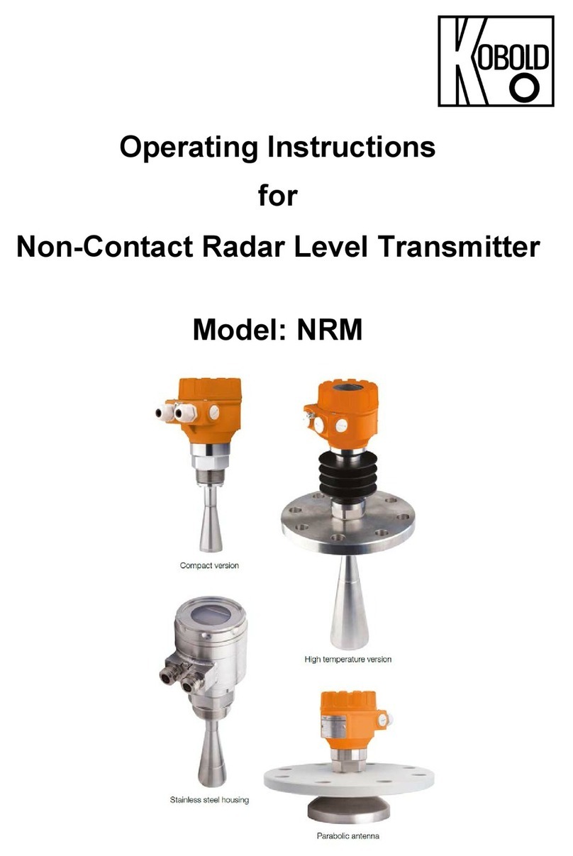
Kobold NRM User manual

Kobold
Kobold NGM-HART User manual

Kobold
Kobold LCI User manual

Kobold
Kobold APM-1 User manual

Kobold
Kobold NMC Series User manual

Kobold
Kobold DF-MA User manual

Kobold
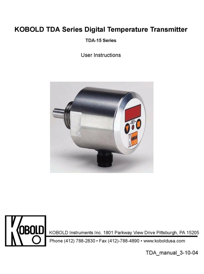
Kobold TDA Series User manual

Kobold
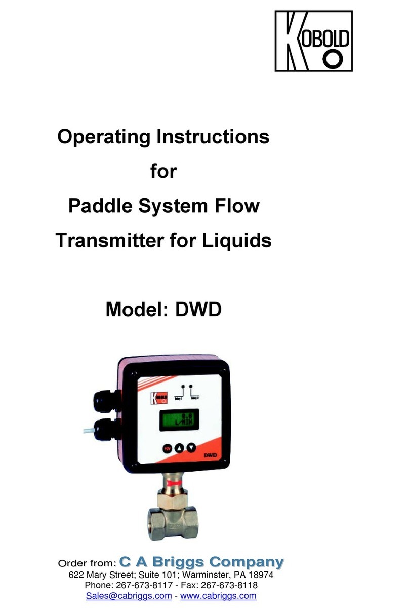
Kobold DWD User manual

Kobold
Kobold PDA User manual

Kobold
Kobold NMC User manual