JUMO CTI-750 User manual

Inductive
Conductivity Transmitter
JUMO CTI-750
Type 202756
B 20.2756.0
Operating Instructions
12.05/00452846


Contents
1 Typographical conventions ...................................................... 5
1.1 Warning signs ..............................................................................................5
1.2 Note signs ....................................................................................................5
2 General ....................................................................................... 6
2.1 Preface .........................................................................................................6
2.2 Design of the JUMO CTI-750 .......................................................................7
3 Inductive conductivity measurement ...................................... 8
3.1 Area of application .......................................................................................8
3.2 Function .......................................................................................................9
4 Instrument identification ........................................................ 10
4.1 Nameplate ..................................................................................................10
4.2 Type designation ........................................................................................11
4.3 JUMO CTI-750 as “Head-mounted transmitter” .......................................11
4.4 JUMO CTI-750 as “Transmitter with separate sensor” .............................12
5 Instrument description ........................................................... 13
5.1 Technical data for transmitter ................................................................13
6 Mounting .................................................................................. 17
6.1 General .......................................................................................................17
6.2 Dimensions / Process connections for head transmitter ...........................18
6.3 JUMO CTI-750 with separate sensor (split version) ..................................19
6.4 Mounting examples ....................................................................................21
7 Installation ............................................................................... 23
7.1 General ......................................................................................................24
8 Setup program ........................................................................ 27
8.1 Function .....................................................................................................27
9 Commissioning ....................................................................... 28
9.1 Head-mounted transmitter or transmitter with separate sensor ................28
9.2 Replacement sensor ..................................................................................28

Contents
10 Operation ................................................................................. 29
10.1 Controls ......................................................................................................29
10.2 Principle of operation .................................................................................31
10.3 Measurement mode ...................................................................................32
10.4 Operator level .............................................................................................32
10.5 Administrator level .....................................................................................40
10.6 Calibration level ..........................................................................................42
10.7 Dilution function .........................................................................................43
11 Calibration ............................................................................... 47
11.1 General .......................................................................................................47
11.2 Calibrating the relative cell constant ..........................................................47
11.3 Calibrating the temp. coefficient of the sample solution ...........................48
12 Maintenance ............................................................................ 56
12.1 Cleaning the conductivity sensor ...............................................................56
13 Eliminating faults and malfunctions ...................................... 57
13.1 Checking the instrument ............................................................................57
14 Appendix .................................................................................. 63
14.1 Before configuration ...................................................................................63

5
1 Typographical conventions
1.1 Warning signs
1.2 Note signs
Danger
This symbol is used when there may be danger to personnel if the
instructions are ignored or not followed correctly!
Caution
This symbol is used when there may be damage to equipment or data if the
instructions are ignored or not followed correctly!
Note
This symbol is used when your special attention is drawn to a remark.
abc1Footnote
Footnotes are remarks that refer to specific points in the text. Footnotes
consist of two parts:
A marker in the text, and the footnote text.
The markers in the text are arranged as continuous superscript numbers.
✱Action instruction
This symbol indicates that an action to be performed is described.
The individual steps are marked by this asterisk.
Example:
✱Remove crosspoint screws.

6
2 General
2.1 Preface
Please read these operating instructions before commissioning the
instrument. Keep the manual in a place that is accessible to all users at all
times.
Please assist us to improve these operating instructions, where necessary.
Your comments will be appreciated.
Phone +49 661 6003-0
Fax +49 661 6003-607
e-mail [email protected]
All necessary settings are described in this manual. However, if any
difficulties should still arise during start-up, please do not carry out
any unauthorized manipulations. You could endanger your rights
under the instrument warranty!
Please contact the nearest subsidiary or the head office in such a
case.

7
2 General
2.2 Design of the JUMO CTI-750
Examples
(1) Transmitter (4) Inductive conductivity sensor
(2) Process connection (5) With or without graphics LC display
(3) Temperature probe
(2)
(1)
(3)
V
ers
i
on:
Transmitter
combined with
conductivity sensor,
Type 202756/xx...
Version:
Transmitter with
separate sensor,
Type 202756/xx...
(1)
(2)
(4)
(5)
(4)
(3)

8
3 Inductive conductivity measurement
3.1 Area of application
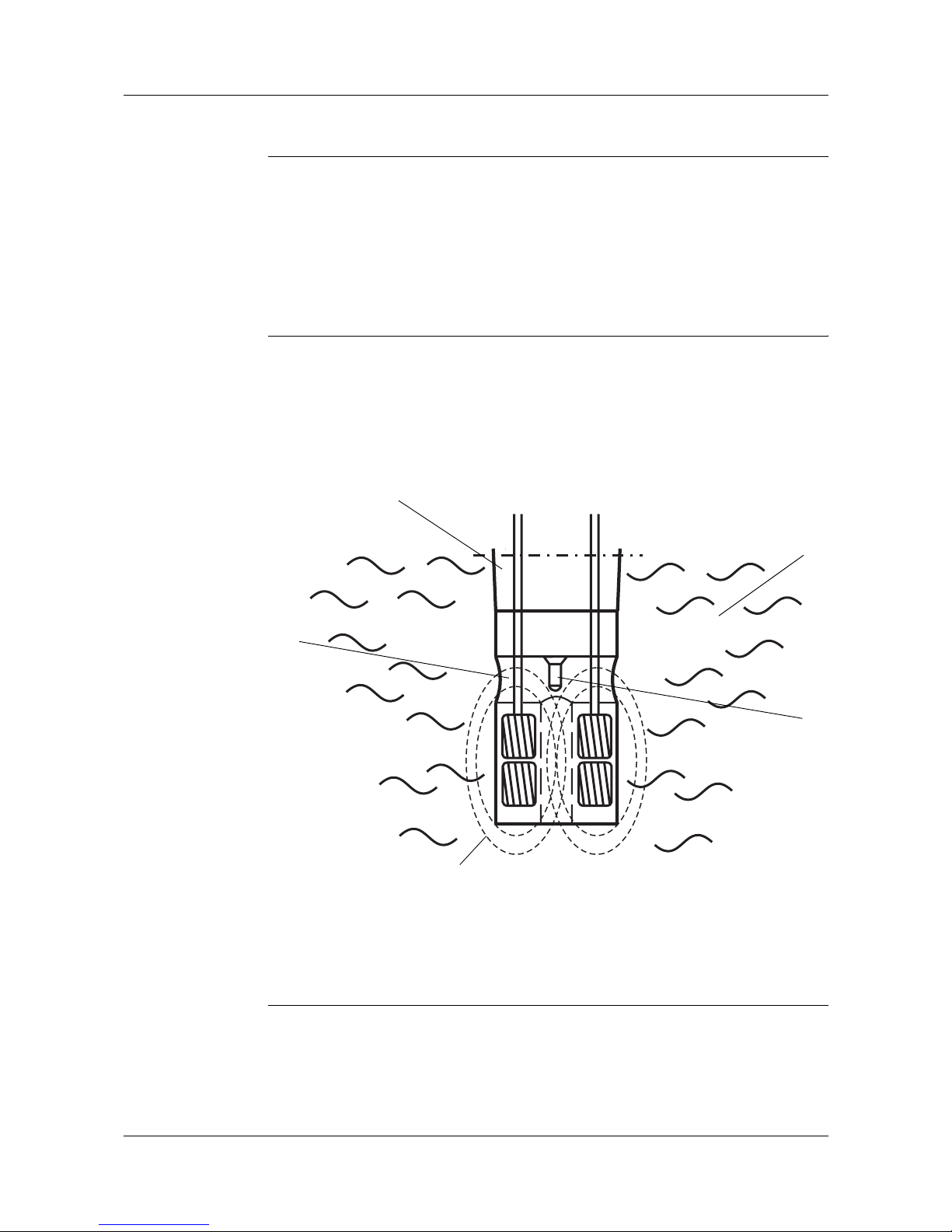
General The inductive measurement method permits largely maintenance-free
acquisition of the specific conductivity, even in difficult media conditions.
Unlike the conductive measurement method, problems such as electrode
decomposition and polarization do not occur.
Brief
description The instrument is used for the measurement/control of conductivity or
concentration in liquid media. It is particularly recommended for use in media
where severe deposits of dirt, oil, grease or gypsum/lime precipitates are to be
expected. The integrated temperature measurement enables fast and
accurate temperature compensation, which is of particular importance when
measuring conductivity. Additional functions, such as the combined
changeover of measurement range and temperature coefficient, enable
optimum application in CIP processes.
Two built-in switching outputs can be freely programmed to monitor limits for
conductivity/concentration and/or temperature. It is also possible to assign
alarm and control functions (dilution).
The instrument is operated either from the membrane keypad and plain-text
graphics display (operator language can be changed over) or through the user-
friendly PC setup program. Simply rotating the housing cover makes it
possible to read the display, regardless of whether the installation is in
horizontally or vertically arranged pipes. By using the setup program, the
instrument configuration data for plant documentation can be saved and
printed out. To prevent any tampering, the instrument can also be supplied
without keypad or display. In this case, the setup program is needed for
programming.
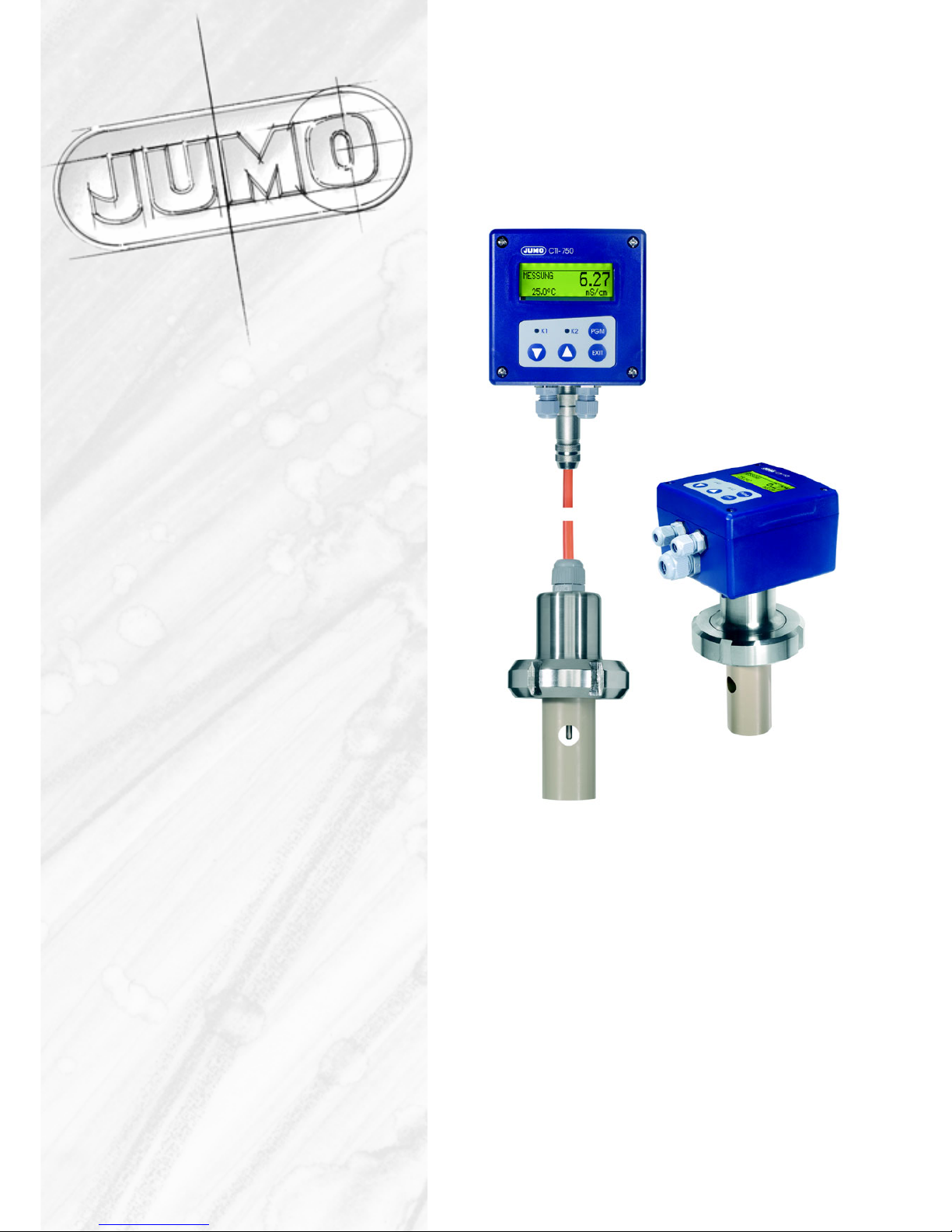
The JUMO CTI-750 is available either as a combined unit (transmitter and
measuring cell together in one unit) or as a split version (transmitter and cell
connected by cable). The split version is particularly suitable for plant
subjected to strong vibration and/or significant heat radiation at the point of
measurement, or for installation on sites that are difficult to access.
Typical areas of
application - CIP cleaning (CIP = Clean In Place/Process)
- concentration monitoring or dosing of chemicals
- food/beverage and pharmaceutical industries
- product monitoring (phase separation of product / product mix / water)
in the beverage industry, breweries, dairies
- control (e.g. phase separation of detergent / rinsing water in
cleaning processes, e.g. bottle cleaning plant, or for container
cleaning)

9
3 Inductive conductivity measurement
3.2 Function
of the
transmitter The JUMO CTI-750 transmitter has been designed for use on site. A rugged
housing protects the electronics and the electrical connections from corrosive
environmental conditions (enclosure IP67). As standard, the device has one
analog signal output each for conductivity/concentration and temperature
respectively. Further processing of the standard signals can take place in a
suitable display/control device, or, for example, directly in a PLC.
The output signals are electrically isolated from one another and from the
medium.
of the
measuring cell The conductivity is measured using an inductive probe. A sinusoidal a.c.
voltage feeds the transmitting coil. Depending on the conductivity of the liquid
to be measured, a current is induced in the receiver coil. This current is
proportional to the conductivity of the medium. The cell constant of the
inductive probe depends on its geometry. The cell constant can also be
affected by components in the immediate vicinity.
(1) Plastic body (4) Sample medium
(2) T-shaped flow
channel
(5) Pt100 temperature sensor
(3) Liquid loop
(2)
(1)
(3)
(4)
(5)

10
4 Instrument identification
4.1 Nameplate
on the
transmitter
on the
connecting
cable
(only with
separate
sensor)
JUMO GmbH & Co. KG
Fulda, Germany
www.jumo.net
JUMO CTI-750
Typ: 202756/15-607-0000-82/000
VARTN: 20/00445843
F-Nr.: 00909467 01 0 0517 0001
DC 19...31 V 3W
ⱕ
F-Nr.: 00909467 01 0 0517 0001
For devices with a separate sensor (type code extensions (2) /60 or /65), the
transmitter and detached sensor are matched to one another at the factory!
When connecting the components, please note that the serial number of the
external sensor (marked on the label attached to the connecting cable) must
match the serial number marked on the nameplate of the transmitter!
The date of manufacture is coded in the “F-Nr.” (serial number):
0517 means manufactured in year 2005 / calendar week 17

11
4 Instrument identification
4.2 Type designation
4.3 JUMO CTI-750 as “Head-mounted transmitter”
x = standard
o = option
1The PC setup program is required for programming the instrument,
see accessories.
2If required, order M12 plug/socket connectors, extra code 580.
2List extra codes in sequence, separated by commas.
4Not available for process connection 686,
expected to be available from April 2006.
(1) Basic type
202756 Inductive transmitter/switching device for
conductivity/concentration and temperature:
JUMO CTI-750
(2) Basic type extensions
10 head-mounted transmitter without display/keypad 1
15 head-mounted transmitter with display/keypad
oo (3) Process connection
o o 607 screwed pipe connection DN50, DIN 11 851
(MK DN50, milk cone)
o o 617 clamp 2 1/2"
o o 686 VARIVENT®DN40/50
o o 690 SMS 2"
(4) Immersion length
o o 000 see “Dimensions / Process connections
(head-mounted transmitter)”
(5) Electrical connection
o o 82 cable glands
o o 83 M12 plug/socket connectors
(instead of cable glands) 2
o o 84 two M16 cable glands and one
blanking plug
(6) Extra codes
x x 000 no extra code
o o 580 1 set M12 plug/socket connectors
o o 767 cell material PEEK
o o 768 cell material PVDF4
o o 844 supply voltage 24 V AC
(1) (2) (3) (4) (5) (6) (6)
Order code / - - - / , ...
Order example 202756 / 10 - 607 - 000 - 82 / 000 ,

4 Instrument identification
12
4.4 JUMO CTI-750 as “Transmitter with separate sensor”
x=standard
o = option
1The PC setup program is required for programming the instrument,
see accessories.
2fixing items (union/ring nuts, mounting brackets) are not
included in delivery.
If required, please include in order, see accessories.
3If required, order M12 plug/socket connectors, extra code 580.
4Not available for process connection 686,
expected to be available from April 2006.
(1) Basic type
202756 Inductive transmitter/switching device for
conductivity/concentration and temperature: JUMO CTI-750
(2) Basic type extensions
20 replacement transmitter without display/keypad 1
(without sensor)
25 replacement transmitter with display/keypad
(without sensor)
60 transmitter without display/keypad 1
including sensor (cable length: 10 m)
65 transmitter with display/keypad
including sensor (cable length: 10 m)
80 replacement sensor with 10 meter cable 3
without transmitter, including adjustment set
(3) Process connection
x x 000 not available
o o o 607 DN50 screwed pipe fitting, DIN 11 851 (MK DN50, milk cone) 2
o o o 617 clamp 2 1/2" 2
ooo 686 VARIVENT
®DN40/50 2
ooo 690 SMS2"
5
(4) Immersion length
x x 000 see “Dimensions / process connections (separate sensor)”
(5) Electrical connection
x 21 fixed cable with M12 socket connector on separate sensor
o o o o 82 cable glands on the operating unit
o o o o 83 M12 plug/socket connectors on operating unit 3
(6) Extra codes
xxxxx 000 noextracode
o o o o 580 1 set M12 plug/socket connectors
o o x x x 767 cell material PEEK
o o o 580 cell material PVDF4
o o o o 844 supply voltage 24 V AC
(1) (2) (3) (4) (5) (6) (6)
Order code / - - - / , ...
Order example 202756 / 65 - 607 - 000 - 82 / 767

13
5 Instrument description
5.1 Technical data for transmitter
5.1.1 General
A/D converter resolution: 15-bit
sampling time: 500 msec = 2 measurements/sec
Supply standard:
19 — 31 V DC (24 V DC nominal), with reverse-polarity protection
ripple: < 5%
power consumption with display: ≤3 W
power consumption without display:≤2.6 W
with extra code 844:
24 V AC ±10%
for operation on SELV or PELV circuits
Rating of the
solid-state
relays
U < 50 V AC/DC
I≤200 mA
Electrical
connection plug-in screw terminals 2.5 mm2or M12 plug/socket connectors
Display (option) graphics LCD with background lighting; adjustable contrast
dimensions: 62 x 23 mm
Permissible
ambient
temperature
(transmitter)
-5 to +50°C
max. 93% relative humidity, no condensation
Permissible
storage
temperature
(transmitter)
-10 to +65°C
max. 93% relative humidity, no condensation
Enclosure
protection
(transmitter)
IP67
Housing polycarbonate
Weight depending on version and process connection
approx. 0.3 — 2 kg

5 Instrument description
14
5.1.2 Conductivity/concentration transmitter
Concentration
measurement
(implemented in
the device
software)
- NaOH (caustic soda)
0 — 15 % by weight or 25 — 50 % by weight
- HNO3(nitric acid); check chemical resistance of the sensor !
0 — 25 % by weight or 36 — 82 % by weight
- customer-specific concentration curve
freely programmable through the setup program (see “special functions”)
Calibration
timer adjustable: 0 — 999 days (0 = off)
Output
signal
Conductivity/
concentration
0 — 10 V / 10 — 0 V
2 — 10 V / 10 — 2 V
0 — 20 mA / 20 — 0 mA
4 — 20 mA / 20 — 4 mA
The output signal is freely scalable.
Burden ≤ 500Ωfor current output
≥ 2kΩfor voltage output
Ambient
temperature
error
≤ 0.1%/°C
Analog output
for “Alarm” Low (0 mA / 0 V / 3.4 mA / 1.4 V) or
High (22.0 mA / 10.7 V) or
a value with a fixed setting (safe value)
Measuring
ranges Four ranges can be selected.
One of these ranges can be activated via an external switch or a PLC.
1not compensated for temperature
Note:
The overall tolerance is made up of the tolerance of the transmitter + the
tolerance of the sensor.
Measurement ranges
Transmitter
Tolerance
(in % of range
span)
0 — 500 µS/cm
≤0.5%
0 — 1000 µS/cm
0 — 2000 µS/cm
0 — 5000 µS/cm
0 — 10 mS/cm
0 — 20 mS/cm
0 — 50 mS/cm
0 — 100 mS/cm
0 — 200 mS/cm
0 — 500 mS/cm
0 — 1000 mS/cm
0 — 2000 mS/cm 1

15
5 Instrument description
5.1.3 Temperature transmitter
Temperature
acquisition manually 0.0 to 25.0 to 150°C/°F
or
automatically
Temperature
measurement
range
0 to 150°C/°F
Characteristic linear
Accuracy ≤0.5% of range
Ambient
temperature
error
≤ 0.1%/°C
Output signal
for
temperature
0 — 10 V / 10 — 0 V
2 — 10 V / 10 — 2 V
0 — 20 mA / 20 — 0 mA
4 — 20 mA / 20 — 4 mA
The output signal is freely scalable.
Burden ≤ 500Ωfor current output
≥ 2 kΩfor voltage output
Analog output
for “Alarm” Low (0 mA / 0 V / 3.4 mA / 1.4 V) or
High (22.0 mA / 10.7 V) or
a value with a fixed setting (safe value)
5.1.4 Temperature compensation
Reference
temperature 15 to 30°C, adjustable
Temperature
coefficient 0.0 to 5.5 %/°C, adjustable
Compensation
range 0 to 100°C
Function - linear
- natural water (EN 27 888)
- non-linear (learning function, see special functions)

5 Instrument description
16
5.1.5 Sensor
Material PEEK (polyether ether ketone) or
PVDF (polyvinylidene fluoride)
Note:
Temperature, pressure and sample medium affect the operating life of the
cell
Temperature of
the sample
medium
120°C max.
briefly 140°C (sterilization)
Pressure 10 bar max.
1not compensated for temperature
Measurement range
Sensor
Tolerance
(in % of range
span)
0 — 500 µS/cm ≤1%
0 — 1000 µS/cm
0 — 2000 µS/cm
≤0.5%
0 — 5000 µS/cm
0 — 10 mS/cm
0 — 20 mS/cm
0 — 50 mS/cm
0 — 100 mS/cm
0 — 200 mS/cm
0 — 500 mS/cm
0 — 1000 mS/cm ≤1%
0 — 2000 mS/cm 1

17
6 Mounting
6.1 General
Installation site Make sure that the site is readily accessible, for calibration at a later time.
The fixing must be secure and free from vibration.
Avoid direct sunlight!
Take care that there is adequate flow through and around the sensor (1)!
If the device is to be mounted in a pipeline, there must be at least 20 mm
clearance between the sensor and the wall of the pipe.
If it is not possible to achieve this minimum clearance, then a limited
compensation can be made through the “Mounting factor” parameter.
For submerged operation in basins, a location must be chosen that is
representative of the typical conductivity or concentration.
Operating
position The JUMO CTI-750 can be mounted in any position.
Screwing in and
unscrewing the
detached
sensor
The cable must not be twisted!
Avoid putting tension on the cable. In particular, avoid tugging it.
Sensor details
(1)
St. steel sleeve: Material 1.4571
Seal: FPM

6 Mounting
18
6.2 Dimensions / Process connections for head transmitter
Installation
variations
Version with
process connection -607
MK DN50
Version with
process connection -690
SMS 2"
Version with
process connection -686
VARIVENT®DN50
(retaining clip not
included in delivery)
Version with
process connection -617
clamp 21/2"
(retaining clip not
included in delivery)

19
6 Mounting
6.3 JUMO CTI-750 with separate sensor (split version)
Transmitter
head
Drilling jig for
wall-mounting

6 Mounting
20
Sensor
component
M12 socket
(PBT / PA)
Cable gland
M16 (PA)
Process connection 686
VARIVENT DN50
(1.4301)
®
Split version with
process connection -607
MK DN50
(union nut not
included in delivery)
Split version with
process connection -690
SMS 2"
(union nut not
included in delivery)
Split version with
process connection -686
VARIVENT®DN50
(retaining clip not
included in delivery)
Split version with
process connection -617
clamp 21/2"
(retaining clip not
included in delivery)
Other manuals for CTI-750
3
Table of contents
Other JUMO Transmitter manuals

JUMO
JUMO MIDAS S22 Ex User manual

JUMO
JUMO B 707025.0 User manual

JUMO
JUMO AQUIS 500 pH User manual

JUMO
JUMO dTRANS p02 User manual

JUMO
JUMO dTRANS T03 Series User manual

JUMO
JUMO DELOS SI User manual

JUMO
JUMO ecoTRANS pH 03 User manual

JUMO
JUMO CTI-500 User manual

JUMO
JUMO ecoTRANS Lf 03 User manual

JUMO
JUMO Wtrans p User manual

JUMO
JUMO dTRANS T02 PCP User manual

JUMO
JUMO 4AP-30 User manual

JUMO
JUMO AQUIS 500 CR User manual

JUMO
JUMO dTRANS p02 User manual

JUMO
JUMO dTRANS T01 HART User manual

JUMO
JUMO 40.2005 User manual

JUMO
JUMO dTRANS O2 01 User manual

JUMO
JUMO JUMO dTRANS p20 DELTA User manual

JUMO
JUMO dTRANS T03 J User manual

JUMO
JUMO JUMO dTRANS p20 DELTA User manual