DF-MA
DF-MA K03/0118 Page 5
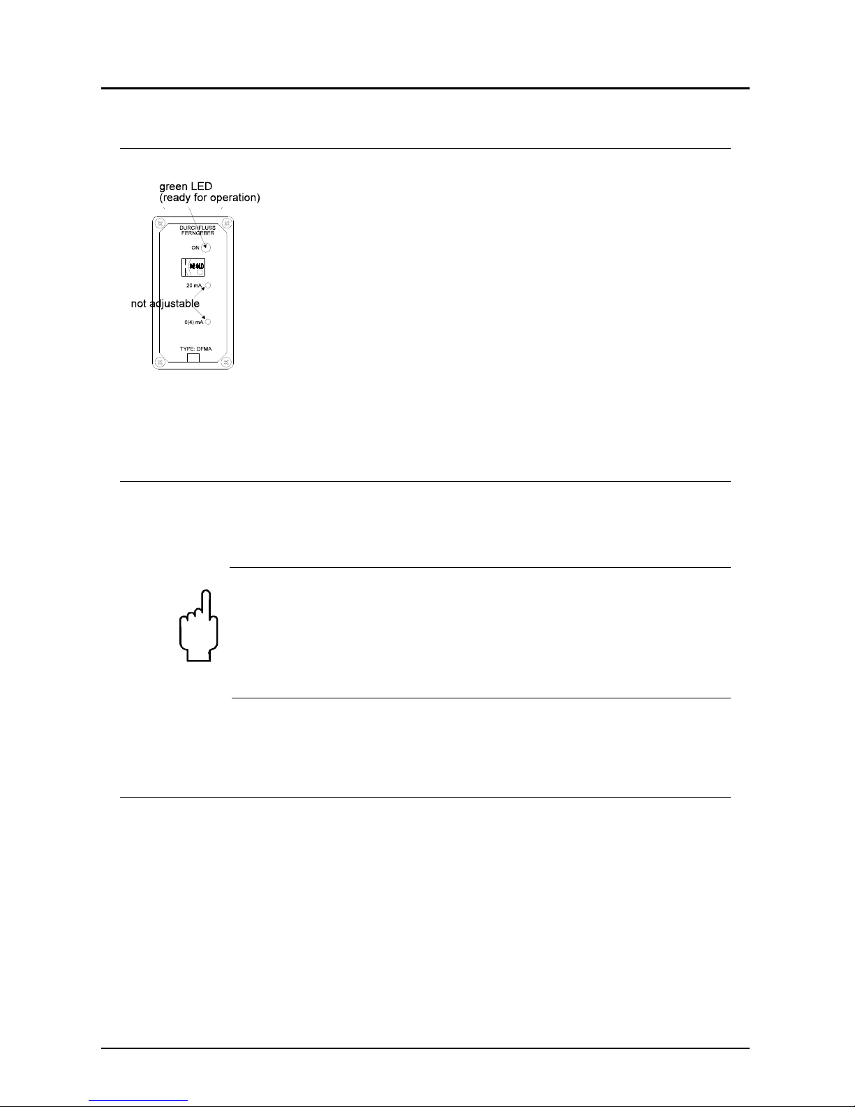
5. Operating Principles
A plastic rotating vane rotates on an axle when a flow throughput occurs. A ring
shaped magnet hermetically sealed in the rotating vane transmits this rotary
motion to a Hall sensor mounted outside of the instrument housing. The elec-
tronics mounted on the housing converts the frequency signal into an analogue
output.
6.Mechanical Connection
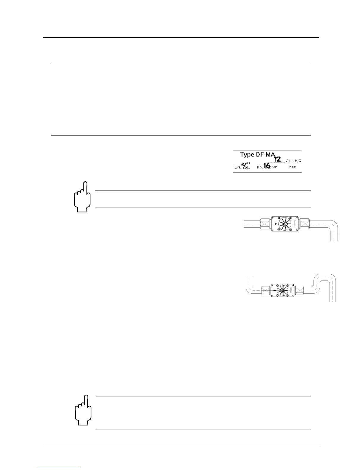
Before installation
Please ascertain whether the actual flow throughput
matches the flow range of the instrument. The flow
range may be obtained from the label.
Warning! If the measuring range is exceeded by more than 20%,
bearing damage may occur.
Please ascertain whether the allowable maximum
operating pressure and operating temperature of the
instruments will not be exceeded.
Make sure that the electrical supply to the instrument
conforms with the equipment operating data.
Remove all transport packing and ascertain that no
packing material is left in the instrument.
The instrument may be installed in any position.
However, the flow must always take place in the
direction of the arrow, while the front face of the
instrument must always be in the vertical plane.
It must be ensured that the instrument housing is continuously filled with the
flow medium, especially for flows from top to bottom. No straight pipe lengths
are necessary at inlet and outlet connections.
Sealing of the connection threads should be carried out with PTFE tape or
similar.
During installation of the instrument, it must be checked that no stress is
applied to the connections. We recommend that the inlet and outlet pipes are
mechanically fixed approximately 50 mm from each instrument connection.
When using material combination IIB,IV,V,VI and VII the instrument connec-
tions may not be rotated.
Check that the connection thread to pipe is fully sealed.
Warning! The threaded connections of the instrument must be
tightened with a suitably sized open ended spanner. Otherwise,
the housing may be stressed which could lead to breakage of the
equipment.
wrong!
right!