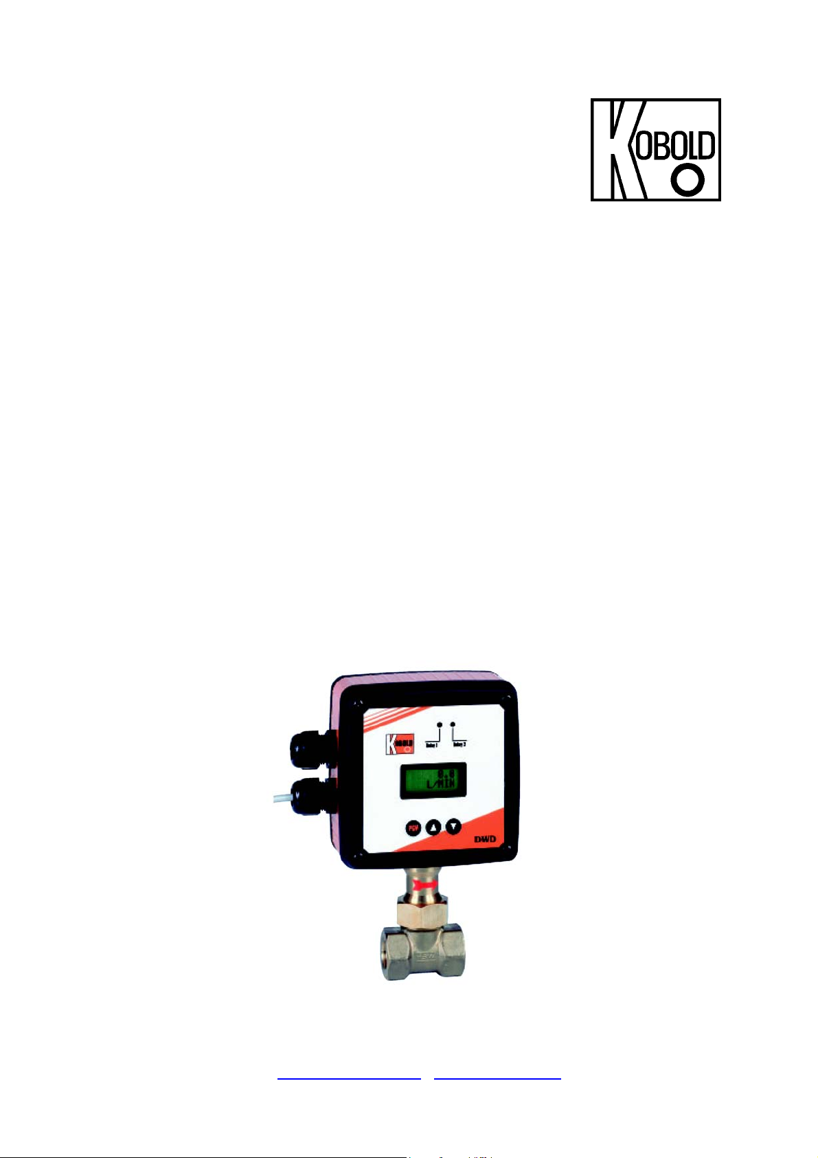
Kobold DWD User manual

Operating Instructions
for
Paddle System Flow
Transmitter for Liquids
Model: DWD
O
Or
rd
de
er
r
f
fr
ro
om
m:
:
C
C
A
A
B
Br
ri
ig
gg
gs
s
C
Co
om
mp
pa
an
ny
y
622 Mary Street; Suite 101; Warminster, PA 18974
Phone: 267-673-8117 - Fax: 267-673-8118
Sa[email protected] - www.cabriggs.com

DWD
page 2 DWD K04/0910
1. Contents
1. Contents........................................................................................................2
2. Note ..............................................................................................................3
3. Instrument Inspection....................................................................................3
4. Regulation Use..............................................................................................3
5. Operating Principle........................................................................................4
6. Mechanical Connection.................................................................................4
6.1 Mounting position.................................................................................4
6.2 Mounting position on electronic view ...................................................4
6.3 Flow direction.......................................................................................5
6.4 Mounting position.................................................................................5
6.5 Mounting in pipe ..................................................................................5
7. Electrical Connection ....................................................................................7
7.1 General ................................................................................................7
7.2 Power supply .......................................................................................7
7.3 Analogue output...................................................................................8
7.4 Voltage output (0-10 V)........................................................................8
7.5 Frequency output.................................................................................8
7.6 Connecting the relais ...........................................................................8
7.7 Interface...............................................................................................8
8. Commissioning..............................................................................................9
8.1 Programming the device ......................................................................9
8.2 Function BATT CHECK .......................................................................9
8.3 Adjusting the switching contacts ..........................................................9
8.4 Adjusting of the output .......................................................................10
8.5 Adjusting of standard indication mode ...............................................11
8.6 Adjusting of response time.................................................................11
8.7 The totaliser .......................................................................................11
8.8 Restriction of access by code number ...............................................12
8.9 Programming the interface.................................................................12
8.10 Mounting the ferrite............................................................................12
8.11 Protection on data loss ......................................................................13
9. Technical Information..................................................................................14
10. Order Codes ...............................................................................................15
11. Maintenance ...............................................................................................16
12. Dimensions .................................................................................................16
13. Declaration of Conformance .......................................................................20
Manufactured and sold by:
Kobold Messring GmbH
Nordring 22-24
D-65719 Hofheim
Tel.: +49(0)6192-2990
Fax: +49(0)6192-23398
Internet: www.kobold.com

DWD
DWD K04/0910 page 3
2. Note
Please read these operating instructions before unpacking and putting the unit
into operation. Follow the instructions precisely as described herein.
The devices are only to be used, maintained and serviced by persons familiar
with these operating instructions and in accordance with local regulations
applying to Health & Safety and prevention of accidents.
When used in machines, the measuring unit should be used only when the
machines fulfil the EWG-machine guidelines.
PED 97/23/EG for DWD-1 and DWD-2
In acc. with Article 3 Paragraph (3), "Sound Engineering Practice", of the
PED 97/23/EC.
Diagram 8, Pipe, Group 1 dangerous fluids
3. Instrument Inspection
Instruments are inspected before shipping and sent out in perfect condition.
Should damage to a device be visible, we recommend a thorough inspection of
the delivery packaging. In case of damage, please inform your parcel service /
forwarding agent immediately, since they are responsible for damages during
transit.
Scope of delivery:
The standard delivery includes:
•Paddle System Flow Transmitter for Liquids model: DWD
•2 fold magnets
•Operating Instructions
4. Regulation Use
The Paddle System Flow Transmitter for Liquids, model DWD, is used for
monitoring and measuring of liquid flows. Only low viscous and homogenous
media may be measured, which do not affect the materials used in the
instrument. Dirt particles and fades could slog on the paddle and provide alarm
signal and measurement errors.

DWD
page 4 DWD K04/0910
5. Operating Principle
The flowing medium presses against a baffle plate that is fastened to a spring
loaded fulcrum. The paddle movement causes displacement of the fulcrum. The
position of a magnet attached to the fulcrum changes and is sensed by a Hall-
effect sensor inside the meter head, isolated from the liquid. This signal is
processed and evaluated by a microchip - based electronics with EEPROM
memory. The digital display indicates the actual flow or totalised value and the
analogue output changes its signal proportional to actual flow. Two adjustable
switching relays for flow set-point monitoring can be adjusted with front buttons.
An RS-232-C serial interface is available as an option.
6. Mechanical Connection
6.1 Mounting position
It is advantageous to install the unit in a straight piece of pipe and to choose a
place of mounting which has the biggest possible distance from elbows, valves
etc. It is especially important to have the biggest possible distance from magnet
valves and ball valves. Please make sure that they are opened as slow as
possible, especially if the pipe after the valve is empty. These measures prevent
the measuring system from flow shocks which can cause damages. We
recommend a straight length of 10 ×d at input side and 5 ×d at the output side
(d= diameter of pipe). The apparatus provides a stable signal when installed at
closer distances, but depending on flow conditions it may be less accurate
6.2 Mounting position on electronic view
Please take in consideration that the mounting has to be done EMI conform in
order to avoid interruptions of operations.
Especially the following points have to be attended:
-The provided ferrites have to be mounted as described.
-Signal and supply cable of the DWD may not directly taken close to 230 V or
380 V wirings.
-The device should not be installed close to inductance, switching loads,
engines or similar sources of inductive fields.

DWD
DWD K04/0910 page 5
6.3 Flow direction
It is essential that the unit is mounted so that flow is as indicated by the arrow on
the body. The unit will not operate unless installed correctly in this way and the
possibility of damage to the unit cannot be excluded.
6.4 Mounting position
Make sure that the supply wires are de-energized.
If the position of display or housing needs to be changed, it can be done on
site. In order to do this, the front and rear covers of the housing should be
removed. The PCB plate can be rotated, after loosening the screws of the PCB
cage. Rotate in 90° steps and re-fasten. Similarly the window of the electronic
front cover can be rotated. Shall the housing be turned, first the circuit board
must be taken out and the hexagon fastening nut must be unscrewed. After
detaching the housing it can be turned.
Please ensure that the PC board and the cable connection do not get
damaged.
6.5 Mounting in pipe
Units with THREADED CONNECTION
damaged while screwing in. In addition, no residue of sealing tape or other dirt
should remain in the pipe.
Units with FLANGED CONNECTION
Suitable flange sealing is to be used. This, as well as mounting screws, is not
included in delivery scope. Take care that the unit does not get damaged during
installation.
As sealing, PTFE tape is recommended. Take care that the unit does not get

DWD
page 6 DWD K04/0910
Units with WELD-ON SLEEVE
The weld-on sleeve is part of delivery scope. It must be removed from the unit by
loosening the union nut. The mentioned drawing dimensions (welding-insertion-
length) must be taken in consideration (27mm-S) (S = pipe wall thickness). A
bore free of burs must be drilled into the pipe. Subsequently the sleeve has to be
welded on and the unit has to be attached. Please ensure that the meter
movement does not get damaged during mounting. During welding of the sleeve,
the flow direction must be kept in mind (groove in the flowing against side).
Opposite of the groove is a paddle limiter, which should not be damaged or
removed during the mounting procedure.
Relay 1 Relay 2
DWD
PGM
OBOLD
117
Ca. 23
72.1
26
UM-SW 32

DWD
DWD K04/0910 page 7
7. Electrical Connection
7.1 General
Make sure that the supply wires are de-energized.
After removal of the back cover, the
terminal blocks can be accessed (see
the following drawing).
The terminal connectors of KL2 are for
connecting the relays, the terminal
connectors of KL1 are for connecting
power supply and output signals.
Prior to wiring the terminal blocks, all
the cables must be pulled through the
corresponding cable gland on the
instrument housing.
7.2 Power supply
The required supply voltage is 24 VDC±10%.
The power supply connection is at KL1.
Connect according to the previous drawing (see chapter 7.1 General): +24VDC (+)
and 0 VDC (-).
In order to prevent the electronic from impermissible potential between pipe and
device, the power supply device must be connected to a grounded power system.
If the leads are switched, the fuse must be changed.
Attention! A supplied ferrite with a coil must be mounted at the
connection cable for magnetic field protection.
+24V DC
0V DC
Frequency-0-10V/4-20mA
Frequency 0-10V/4-20mA
Fuse 2,5A

DWD
page 8 DWD K04/0910
7.3 Analogue output
The connection is at terminal strip KL1.
Connect according to drawing chapter 7.1 General:
−0-10V/4-20 mA
+0-10V/4-20 mA
The maximum load is 500 Ω.
A supplied ferrite with a coil must be mounted at the connection cable for
magnetic field protection.
7.4 Voltage output (0-10 V)
Connection is to block KL 1 according to the drawing. (See reference point
8.4). At the connection cable a ferrite must be fixed. The ferrite is included in
delivery.
7.5 Frequency output
Connection is to block KL 1 according to the drawing. (See reference point
8.4). At the connection cable a ferrite must be fixed. The ferrite is included in
delivery.
7.6 Connecting the relais
The switching contacts can be connected at KL2. For wiring diagram please refer
to the drawing. A supplied ferrite with a coil must be mounted at the connection
cable for magnetic field protection.
7.7 Interface
As special option, the DWD is also available with an interface RS232C. The
provided serial cable will be connected to the PC board via a plug. A supplied
ferrite with a coil must be mounted at the connection cable for magnetic field
protection.
Please note with this option the comments and chapter
8.9 Programming the interface.

DWD
DWD K04/0910 page 9
8. Commissioning
8.1 Programming the device
The device is equipped with 3 buttons on the front cover. The PGM button is to
select a menu point and to set the adjusted values. With the buttons ⇑and ⇓
values of each parameter can be adjusted. Button ⇑raises value. Button ⇓
decreases the value. Pressing this button one time changes the value by one
digit. If you keep the buttons on hold, the value changes continuously. After some
time, speed increases. At some points of the menu, the DWD informs you which
buttons have to be pressed as next step. For example PIN [+/-], whereby +
corresponds to button ⇑and – to button ⇓. The device returns back automatically
after some time to the run mode set under DWD MODE (see chapter 8.3
Adjusting of standard indication mode), if no button is pressed. In the first line, the
menu point is always shown and in the second line, the adjusted parameter value
is shown.
8.2 Function BATT CHECK
This function ensures that in case of power failure, dates of the totaliser are still
available. Therefore, this function should always be switched on in case of using
the totaliser (ON). For more information please see chapter 8.7 The totaliser.
If the totaliser is not used, it is recommended to switch off this function (OFF),
because in case of interruption of power, the DWD only works properly after
resetting the unit.
With button PGM, the menu is selected and with ⇑or ⇓, the function is to be set.
Pressing of PGM after adjusting the parameter sets the function.
8.3 Adjusting the switching contacts
Press button PGM until RELAIS 1 appears. Line 2 shows the actual switch point.
By pressing ⇑or ⇓, the value of the switch point can be adjusted. For setting the
switch point, PGM has to be pressed and “*” appears. After some time, the star
disappears. Adjusting the switch point is now completed. Pressing button PGM
once more results in RELAIS 2 appearing.
Adjustment is as described under RELAIS 1.
When the adjusted value is reached, a lamp is illuminating for control. The green
lamp (A) is assigned to RELAIS 1, the red lamp to RELAIS 2 (B).

DWD
page 10 DWD K04/0910
8.4 Adjusting of the output
The DWD is equipped with a current and a voltage output. The outputs can only
be used alternatively. Only one pair of connectors is available for both functions.
Connection is to clamp block KL1 (see chapter 7.2 Power supply and 7.3
Analogue output respectively drawing of the board). At menu OUTPUT, analogue
or voltage output can be activated. With the buttons ⇑and ⇓, the function will be
selected.
Button PGM sets the adjustment. At the option frequency output the max.
frequency can be adjusted between 125-32000 Hz. Therefore button P must be
pressed after entering the frequency function. Then the max. frequency can be
adjusted with the buttons ⇑and ⇓. Now the adjusted max. frequency corresponds
to the upper range value.
Allocation measuring value - output
Measuring value Output 4-20 mA Output 0-10 V
0 L/min 4 mA 0 V
ME 20 mA 10 V
Initial of the measuring range at 4-20 mA
The initial of the measuring range of the Paddle System Flow Transmitter for
Liquids DWD does not start at zero. At a measuring range of e.g. 10 – 100 L/min,
the output is 4 mA between 0 and 9,99 L/min. From 10 L/min the analogue output
increases linear from 5,6 mA to 20 mA at 100 L/min.
The analogue value at the initial of the measuring range calculates as follows:
MA = D/DEW x16+ 4
MA = mA value at the initial of the measuring range
D = flow (initial value)
DEW = flow (final value)
Initial of the measuring range at 0-10 V
The initial of the measuring range of the Paddle System Flow Transmitter for
Liquids DWD does not start at zero. At a measuring range of e.g. 10 – 100 L/min
the output is 0 mA between 0 and 9,99 L/min. From 10 L/min, the analogue
output increases linear from 1 V to 10 V at 100 L/min.
The analogue value at the initial of the measuring range calculates as follows:
VW = D/DEW x10
VW = volt value at the initial of the measuring range
D = flow (initial value)
DEW = flow (final value)

DWD
DWD K04/0910 page 11
8.5 Adjusting of standard indication mode
It is possible to choose between 2 different indication modes. At the point in the
menu DWD MODE, you can select the modes. In the second line, the valid mode
is shown. FLOW means indication of instantaneous flowrate. TOTAL means that
the value of totaliser (total accumulated flow) is shown. You can choose the
required indication by using button ⇑or ⇓. Button PGM sets the adjustment.
Only the selected standard indication is permanently visible. During programming
the display will revert back to the standard indication after some time of inactivity
during programming.
8.6 Adjusting of response time
The DWD Paddle System Flow Transmitter for Liquids makes 18870
measurements per minute. If the result of each measurement was shown on the
display, the indication would change continuously and it would be very difficult to
read the erratic indication. Therefore, it is possible to program a gate time
between 0 and 3,4s. Then the average value of the values measured within the
programmed time is shown. A long gate time causes a slowly changing indication
which is easy to read. We recommend to maintain the standard adjustment of 1s.
For changing the integration time you can choose the desired time with help of
the buttons ⇑and ⇓in menu INT.[s]. Button PGM sets the adjustment.
8.7 The totaliser
The device is equipped with a totaliser that displays the total accumulated flow
over time. (Menu point TOT: X.) X corresponds to the respective quantity. The
unit results from flow rate units. (for example l/min corresponds to l). Pressing
button ⇑pushes the memory down to zero.
PRESS
<
+
>
to reset appears (+ = ⇑). Now press ⇑and hold for approximately 20
seconds. After this time, the total display is reset.
In case of power failure, the totalised value will be stored in memory. If voltage is
back again, the device notifies POWER LOW / PRESS P & ⇑respectively
PRESS P & ⇑. After pressing PGM and ⇑(at same time), the DWD changes back
to standard mode. After that, the device starts counting from the amount that was
present at the time of power failure. This guarantees that the operator is aware
that power supply was interrupted, and so the amount indicated perhaps does not
correspond to the actual total.
Attention! The power failure supervising function only works if at
menu point the function is activated (ON) (see chapter 8.2 Function
BATT CHECK).
The device has an 8 digit display, so that a big capacity is available. Depending
on the flow, units and time of flow may be quite different. If the maximum

DWD
page 12 DWD K04/0910
indication value is reached, DWD starts with zero again. At the totaliser menu,
you see the actual value immediately after switching over to the totaliser function.
That means, when the totaliser menu is selected, the indication is always
updated. The actual value is only indicated if the totaliser is defined as standard
indication. (The display is on.)
8.8 Restriction of access by code number
In order to restrict access of unauthorised persons to the programming menu, it is
possible to activate a code number. At menu point PIN [+/-], it is possible to
adjust any code number between 1 and 999 by means of the buttons ⇑and ⇓. By
pressing PGM and ⇑at the same time, the programmed code number is
activated. ENABLE appears on the display. That means that the function is
active. If an adjustment in any menu should be changed, the operator is always
asked for the code number. The number can be entered as described above.
After that PIN OK! appears. Now the adjustment can be changed. If PIN NOT
OK! appears, input was wrong. You now can repeat entering the code number.
Attention! If the number is forgotten, the adjustments cannot be
changed.
At menu point PIN [+/-] restriction of access can be switched off. Therefore, the
code number has to be entered as described above. PIN OK! and thereafter
DISABLE appears.
8.9 Programming the interface
Under menu point “DWD ADR:”, the address of each device can be programmed
(selection by ⇓, input by PGM). For more details, please see our data sheet for
devices with interface. It is only added to devices which are equipped with this
option (also see chapter 7.7 Interface).
8.10 Mounting the ferrite
The KOBOLD Paddle System Flow Transmitter for Liquids DWD is EMI certified
and comes up to the corresponding norm. The EMI directive will only be
achieved, if the provided ferrites are mounted as mentioned under 7.2 Power
supply, 7.3 Analogue output, 7.4 Voltage output (0-10 V) and 7.5 Frequency
output . If not, serious malfunctions can appear depending on the mounting
position.
(q.v. 1.2)
IMPORTANT! Always mount the ferrite !

DWD
DWD K04/0910 page 13
8.11 Protection on data loss
If your device is operated on incorrect EMI conditions, it could come to data loss
respectively damages of coded data in extreme cases.
As the item need these data for a correct function there hereby is an anticipate
protection.
In this case the item is showing K DATA MISSING.
So that this information is available for the occupant, even in case of a use of the
analogue-voltage or frequency output, impermissible values will normally be
transferred. These are 1mA, 20V, respectively 0 Hz.
In order to re-establish the function of the item in such a case, the necessary
software is saved additionally for safety reasons. The software can be load again
with the menu item FACTORY RESET. Therefore push the button×or Øin the
menu FACTORY RESET. You will be asked to start the action (Y) button ×or to
break up (N) buttonØ.
ATTENTION! When starting the application, all adjusted data as
switch points, totalisator value etc. will be lost (Reset to the original
factory setting).
Please consider this and keep the data in mind before starting the procedure.
After the reestablishment has been started, you will get informed about the status
of the procedure. When the flow indication on the display appears, the operation
is over. The device is working as usual again. Please consider that for instance
the switch points have to be newly installed again.
We would like to point out that the data loss occurs only if the item is used under
forbidden conditions. Therefore it is really necessary to open corresponding
arrangements in order to avoid a new data loss.
This could be: mounting the provided ferrites, installation of the device at another
position, changing the cabling within the installation (no measure or feed lines of
the transmitter near high voltage feed cable). Reducing of radiation or magnetic
field or even the installation of suitable electrostatic shields.

DWD
page 14 DWD K04/0910
9. Technical Information
Turndown ratio: 1 : 10 standard (for example: 10-100 l/min)
Accuracy: +/- 1.5 % FS
Medium temperature: -20 ... +120 °C (other on request)
Max. pressure: 25 bar (DWD-x5.., DWD-x6..)
16 bar (DWD-x7)
(other on request)
Flow: direction of arrow
Mounting position: any
Analogue output: 4 – 20 mA; max. load 500 Ω
or 0 – 10 V / frequency output
Relay output: 2 change-over contacts(max. 230 V; 1 A)
fully adjustable
Display: LCD DOT-Matrix-module
2 x 8 digits (illuminated)
Power supply: 24 VDC +/- 10 %
Current: max. 200 mA
Fuse 2,5 A
Protection: IP 65
Interface (optional): RS 232C

DWD
DWD K04/0910 page 15
10. Order Codes
(Example: DWD-15 R10 3 R T 0)
Paddle System Flow Transmitter for Liquids model DWD-1.. with thread connection
Flow range
(l/min)
Material combination
(pendulum system/ T piece) Connection Supply Direction of
flow
Location of
indicator Option
min.
Water
max.
Water
St. steel/
Brass
St. steel
St. steel
St. steel/
PVC
1 25
DWD-15.. DWD-16.. DWD-17.. R10= G 3/8*
N10= 3/8 NPT*
3= 24 VDC
R= from right to left
L= from left to right T= above lead
0= without
7= RS232C
interface
1 55
DWD-15.. DWD-16.. DWD-17.. R15= G 1/2*
N15= 1/2 NPT*
5 100
DWD-15.. DWD-16.. DWD-17.. R20= G 3/4*
N20= 3/4 NPT*
T= from top to bottom
B= from bottom to top
R= right of lead
L= left of lead
6 150
DWD-15.. DWD-16.. DWD-17.. R25= G 1*
N25= 1 NPT*
10 250
DWD-15.. DWD-16.. DWD-17.. R32= G 1 1/4*
N32= 1 1/4 NPT*
20 400
DWD-15.. DWD-16.. DWD-17.. R40= G 1 1/2*
N40= 1 1/2 NPT*
50 600
DWD-15.. DWD-16.. DWD-17.. R50= G 2*
N50= 2 NPT*
*Model DWD-15... female thread to R40, above external thread; Model Typ DWD-16.../DWD-17... female thread to R40, above external thread
Paddle System Flow Transmitter for Liquids model DWD-2.. with flange connection
Flow range
(l/min)
Material combination
(pendulum system/ T piece) Connection Supply Direction of
flow
Location of
indicator Option
min.
Water
max.
Water
St. steel/
Brass
St. steel
St. steel
St. steel/
PVC
1 25
DWD-25.. DWD-16.. - F10= DN 10
A10= 3/8” ANSI
3= 24 VDC
R= from right to left
L= from left to right T= above lead
0= without
7= RS232C
interface
1 55
DWD-25.. DWD-16.. - F15= DN 15
A15= 1/2” ANSI
5 100
DWD-25.. DWD-16.. - F20= DN 20
A20= 3/4” ANSI
T= from top to bottom
B= from bottom to top
R= right of lead
L= left of lead
6 150
DWD-25.. DWD-16.. DWD-17.. F25= DN 25
A25= 1” ANSI
10 250
DWD-25.. DWD-16.. DWD-17.. F32= DN 32
A32= 1 1/4” ANSI
20 400
DWD-25.. DWD-16.. DWD-17.. F40= DN 40
A40= 1 1/2” ANSI
50 600
DWD-25.. DWD-16.. DWD-17.. F50= DN 50
A50= 2” ANSI
Baffle plate system-flow transmitter DWD-35../ DWD-36.. with weld-on part, DWD-37.. with boring pipe box
Flow range
(m3/h)
Material combination
(pendulum system/ weld-on part)For pipe
cross-section Supply Direction of
flow
Location of
indicator Option
min.
Water
max.
Water
St. steel/
St. steel
St. steel
St. steel
St. steel/
PVC
1.2 24 DWD-35.. DWD-36.. DWD-37.. W40= DN 40
3= 24 VDC
R= from right to left
L= from left to right T= above lead
0= without
7= RS232C
interface
3.0 36 DWD-35.. DWD-36.. DWD-37.. W50= DN 50
4.8 60 DWD-35.. DWD-36.. DWD-37.. W65= DN 65
T= from top to bottom
B= from bottom to top
R= right of lead
L= left of lead
7.2 90 DWD-35.. DWD-36.. DWD-37.. W80= DN 80
12 144
DWD-35.. DWD-36.. DWD-37.. W1H= DN 100
18 225
DWD-35.. DWD-36.. DWD-37.. W1Z= DN 125
24 330
DWD-35.. DWD-36.. DWD-37.. W1F= DN 150
42 600
DWD-35.. DWD-36.. DWD-37.. W2H= DN 200
72 900
DWD-35.. DWD-36.. - W2F= DN 250
102 1200
DWD-35.. DWD-36.. - W3H= DN 300
150 1800
DWD-35.. DWD-36.. - W3F= DN 350
180 2400
DWD-35.. DWD-36.. - W4H= DN 400
300 3600
DWD-35.. DWD-36.. - W5H= DN 500
We require the following details as well as the order number:
medium, viscosity, service temperature, operating pressure, flow
range within the values below the ration min/max 1:10

DWD
page 16 DWD K04/0910
11. Maintenance
The DWD is essentially maintenance-free. However, depending on the degree of
pollution in the medium, it is recommended that the paddle movement is being
inspected and cleaned from time to time, if necessary.
Under no circumstances attempt to remove the paddle from the body, as this will
destroy the calibration.
Maintenance work may only be carried out when all electrical lines
are currentless and the pipes are emptied and depressurised.
Attention! To separate the instrument from the T-piece, unscrew the
union nut and tilt the unit as much as possible to direction of flow.
Then lift the DWD with paddle out of the fitting. Please perform all
operations with great care to avoid damage especially to the paddle .
12. Dimensions
DWD-15.. up to 1 ½“ with female thread connection
DWD-16.. and DWD-17.. up to ¾“ with female thread connection
Values in ( ) are valid for DWD-16...
Values for DWD-17... on request
NW L (mm) H (mm)
3/8” 50 180
1/2” 50 180
3/4” 50 180
1” 50 185 (201)
1 1/4” 50 190 (201)
1 1/2” 50 194 (201)

DWD
DWD K04/0910 page 17
DWD-15.. from 2” with male thread connection
DWD-16.. and DWD-17 from 1” with male thread connection
Values in ( ) are valid for DWD-16...
Values for DWD-17... on request
NW L (mm) H (mm)
1” 135 185 (201)
1 1/4” 170 190 (201)
1 1/2” 170 194 (201)
2” 170 202 (211)

DWD
page 18 DWD K04/0910
DWD-2.. with flange connection
Values in ( ) are valid for DWD-26...
Values for DWD-27... on request
DN DL (mm)
K (mm) L (mm) H (mm)
10 90 60 155
180
15 95 65 155
180
20 105 75 160
180
25 115 85 160
185 (201)
32 140
100 190
190 (201)
40 150 110 190 194 (201)
50 165
125 190 202 (211)

DWD
DWD K04/0910 page 19
DWD-3.. with weld-on connection
Values are valid for DWD-35... and DWD-36...
Values for DWD-37... on request
NW H (mm)
from
DN 40 180

DWD
page 20 DWD K04/0910
13. Declaration of Conformance
We, M/s KOBOLD Messring GmbH, Hofheim-Ts. Germany, declare under our
sole responsibility, that this Product:
Paddle System Flow Transmitter for Liquids Model: DWD-...
which relates to this certificate, conforms to the standards listed below:
EN 55011 1991
EN 50082-2 1995
DIN EN 61010 Part 1 1994
following the provision of European Directives:
2004/108/EC
2006/95/EC
Hofheim, 30 Sept. 2002
H. Peters M. Wenzel
General Manager Proxy Holder
Table of contents
Other Kobold Transmitter manuals

Kobold
Kobold APM-1 User manual

Kobold
Kobold LCI User manual

Kobold
Kobold AFB User manual

Kobold
Kobold PAS User manual

Kobold
Kobold Heinrichs UMC3 User manual

Kobold
Kobold AFK-E Series User manual

Kobold
Kobold NGM User manual

Kobold
Kobold NMC User manual

Kobold
Kobold NEO-7 Series User manual

Kobold
Kobold NGM-HART User manual