Kohler Bardon K-8787T-C01 User manual

·
·
·
Please read these instructions carefully to familiarize
yourself with the required tools, materials, and installation
sequences. Follow the sections that pertain to your
particular installation. This will help you avoid costly
mistakes. In addition to proper installation, read all
operation and safety instructions.
All information in these instructions is based upon the
latest product information available at the time of
publication. Kohler China reserves the right to make
changes in product characteristics, packaging, or
availability at any time without notice.
These instructions contain important care, cleaning, and
warranty information -
.
please leave instructions for the
consumer
·
·
·-
·
·
·
·
·
·
·
·
·
·
·
·
·
·
Open end/adjustable wrenches
Tape measure
Basin wrench
Pipe wrench
Square
Level
Pliers
Socket wrench with sockets
Screw driver
Seal tape
Connection wire
Wire cutter
Insulation tape
Bushing
·
·
·
·
·
·
·
·
·
·
·
·
·
·
/
RECOMMENDED TOOLS AND MATERIALSRECOMMENDED TOOLS AND MATERIALS
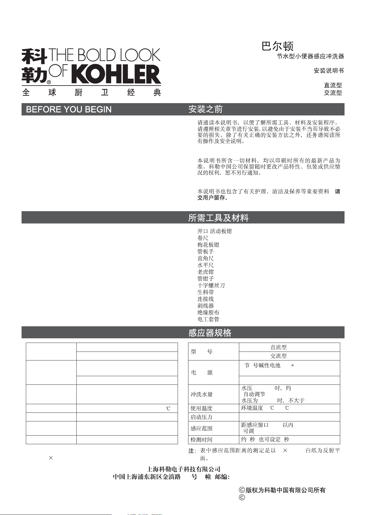
SENSOR SPECIFICATIONSENSOR SPECIFICATION
Model 8787T-C03(AC)
8787T-C01(DC)
Power
4 AA size alkaline batteries
(8787T-C01)
""
220V AC 50/60Hz(8787T-C03)
Liter per flushing
Water pressure 0.3 MPa: about 2~4L
(Automatic adjustment)
Water pressure 0.1MPa no more than 3L
Temperature Environmental temperature: 1 to 60
Starting pressure 0.05~0.7MPa
Sensing distance 80cm away from sensing window
(adjustable)
Testing time About 2 seconds (or set to 5 seconds)
30 30cm2
Note: The sensing distance in the table is measured with a
30 30cm white board as the reflecting surface.
2
8787T-C03( )
8787T-C01( )
4 5 (AA 4)
(8787T-C01)
220V AC 50/60Hz(8787T-C03)
0.3 MPa 2~4L
()
0.1MPa 3L
:1 ~60
0.05~0.7MPa
80cm
()
2( 5)
BARDON
TOUCHLESS URINAL SENSOR (WATER SAVING)
INSTALLATION INSTRUCTIONS
K-8787T-C01(DC/ )
K-8787T-C03(AC/ )
-1-
, 2007
Copyright Kohler China Ltd., 2007
18 E 201206
1020018-T01-C

PRODUCT PAGE
1020023
Stop Valve Assy.
Big Ring"O"
"O"
Adjusting Bolt
Center Unit
1019265-
1019265-
SC
CP
Sensor Cover
Adjustment Nut
Spring
Nut
Inlet Connenction
Connection Ring"O"
"O"
1021431
Pertain 2
Screw(4 Pcs) 3x8M
(4 ) 3x8M
1019269
Bracket
Plug In
1020021
Rubber Plugs
1020011
Angles
Long Screws
(4 pcs)
M4 50
(4 )
M4 50
Cover Screw
(2 M3 6
pcs)
(2 )
M3 6( )
1020029
Flushing Valve Assy.
1020979
Solenoid
Valve Assy.
1019266
Sensor Lens
Seal Washer Control Box Battery Cover
1019270
Control Box Assy.
1021642
Fixed Cap
1020028
"O"
"O"
Big Ring
1021472
Filter
Connection Ring"O"
"O"
Outlet Connection
1021431
Pertain 2
Small Ring"O"
"O"
Nut
AC
16305T-NA
8787T-C03 Use only
8787T-C03
Connector
-2-
1020018-T01-C

ROUGHING-IN
K-4960T-ET
97 +40
0
160
158
158
3/4 SPUD
"
320 40
76
5
533
2 N.P.S. TAP
"
K-4960T-ER
97 +40
0158
158
320 40
533 2 N.P.S. TAP
"
UNIT: mm
Notice: a. The dimensions above are just for reference.
b. The connection take between the outlet connection
and urinal is not supplied in this package.
a.
b.
Notice: To ensure an effective flush performance,
strongly recommended inner diameter of
water supply (including water meter, valve,
etc.)is no less than 20mm, and supplied water
pressure (sensor inlet dynamic pressure) is
0.1MPa~0.55MPa(Go with K-4960T).
(
) 20mm (
) 0.1MPa~0.55MPa( K-4960T)
R1/2
1/2"
R1/2
-3-
INSTALLATION
1
Notice:
. Determine the installation location per rough-in dimensions.
Chisel out a slot and install the supply tubing. Turn off the
water supply. The depth of the slot is no less than 105mm.
see the figure right for rough-in dimension requirement.
installation location:
a. No light shall enter or be reflected into the
sensing window.
b. No reflectible objects in front of the sensing
window (e.g., mirror, polishing stainless
steel and some other polished plate).
c. No strong ultraviolet radiation or
electromagnetic field nearby.
While installing 8787T-C03(AC), chisel out the slot
indicated in the dot line area of figure right for installation of
bushing.
1.
105mm
a.
b. (
)
c.
8787T-C03( )
42
Installation Site
160
50
90
110
85
110
160
50
Install bushing
1020018-T01-C

2.
(3)
2. Remove the dust-proof covers from the valve and install
the inlet/outlet connections. The outlet connector shall face
away from the wall and at the center of the urinal. Place the
flushing valve box into the slot, adjust its level and square
with battens. Then screw down the nut at the inlet and
outlet position. The connections please refer to the rough-
in in page 3.
WRater Supply( ecommended Inner
Diameter Is More Than 20mm)
( 20mm)
Inlet Connection
Nut Battens
Outlet Connection
Nut
AC Power Unit
Connect control box while
installing 8787T-C03
8787T-C03
Outer diameter
of bushing is no
more than 25mm
25mm
-4-
Please directly reference to Step 3 when installing 8787T-
C01 (DC).
Please match 16305T-NA AC power unit when installing
8787T-C03 (AC). The way of installation is as below.
a. Outlet of AC power unit upward prohibited.
b. Do not connect 220V AC power supply to DC wiring
terminal.
c. Do not damage the covering of AC power unit or
remove screws to avoid leakage.
CAUTION: Outlet downwards
Outlet upwards
Connect to
sensor
Connect to AC
Power supply
A.1
2
Connect to AC
Power supply
8787T-C01( ) 3
8787T-C03( ) 16305T-NA
a.
b. 220V
c.
A. Fig. #1: AC power unit connection way 1:
AC power unit is directly connected to electric control box.
Fig. #2 : AC power unit connection way 2:
AC power unit is connected to electric control box by
connection wire.
Connect to
sensor
Fig. #2
2
AC
AC Connector
16305T-NA
AC power unit
16305T-NA
AC Power Unit
Connector
Wire prepared
by customer
Connect with the same color ,
and protect connect area by insulation tape.
wire
Connector
Fig. #1
1
1020018-T01-C

B
CAUTION:
. When installing the AC power unit in cassette, please
layout the bushing according to Fig. #3, and thread the
wire through the bushing.
Fig. #3: Connection sketch AC power unit install in
cassette.
One AC power unit can supply two sensors
at most.
B.
3
Fig. #3
3
Connect 220V AC
220V
Bushing
-5-
C
CAUTION:
. When installing the power unit on the ceiling, please
layout bushing according to Fig. #4 and thread wire
through the bushing.
Fig. #4: Connection sketch while installing power unit on
the ceiling.
One AC power unit can supply two sensors
at most.
Notice: a. Keep the connector away from water.
b. Don t mistake the direction of inlet and
outlet.
’
Don t lose the connection O rings.¢
c. Do not connect the DC output of AC power
unit to AC power supply.
d. Do not connect to power supply while
installing. Connection line is not supplied.
AC connection wire with insulating sleeving
is recommended. Wire of which the
nominal section area of conductor is not
less than 0.5mm is also recommended.
DC connection line use wire of which the
nominal section area is not less than
0.3mm . It is cut according to acted
installation requirements(The length of cut
wire is recommended less than 10m).
e. The head AC power supply must be
protected with appropriate fuse.
f. Please confirm the AC power supply and
water supply should be shut off before
maintaining the products with AC power
related.
g.
2
2
""
:a.
b.
c.
d.
0.5mm
0.3mm
( 10m)
e.
f.
g
2
2
. O""
C.
4
Fig. #4
4
Bushing
AC power unit
Ceiling
1020018-T01-C

-6-
3
Notice:
. Connect the control box with power on(see step 5) with
solenoid valve, and check the leakage by manual flushing
for several times. Once it is confirmed that there is no
leakage, place the mold sheath onto the valve box and
apply slurry into the crevice around the valve box and
smooth the surface.
a. Please confirm the completion of step 2.
b. Please avoid the damage of the sensor
cover or breaking the cord.
3.(5)
a.
b.
4. When the slurry turns solid, remove the short screws, pull
out slurry mold, mount the bracket assy and secure with
long screws.
4.
5.
a. Buckle the sensor cover into the wall slightly above
bracket assy.
b. Press the sensor cover down along the wall and fit tightly
into the bracket assy.
c. Push upward with basin wrench and rotate clockwise to
lock the sensor cover.
While using DC power for 8787T-C01, remove the battery
cover and put in 4 "AA" size alkaline batteries and tighten
the screws. C
While using AC power for 8787T-C03, connect solenoid
valve with control box assy, and then connect AC power
supply to AC power unit.
Install the cover as shown in the figure:
onnect solenoid valve with control box assy.
At last.
5.
8787T-C03( )
a.
b.
c. (
)
8787T-C01( ) 4 5
Valve oxB
Tiles
1020014
Slurry oldM
40
Slurry Mold
Short Screw M4 10
M4 10
Screw M3 8
m3 8
a
b
1020018-T01-C

-7-
Notice: a. Don t mistake the polar of the batteries and
don t mix new and used batteries together.
When no enough power, the indicator
will flash continuously (20 times at most).
When out of power, the indicator will flash
every 2 seconds and the sensor will not
work until new batteries are supplied. When
changing, remove the battery cover and put
in new batteries. No need to reset the
program after the battery changed.
b. Put on clean gloves when install sensor
cover to avoid surface injury by cement or
sand.
¢
¢
a.
(20)
2
b.
Indicator
Battery Indicator
c
90o
INSTALLATION IN OTHER METHODSINSTALLATION IN OTHER METHODS
USER S GUIDE¢USER S GUIDE¢
Don t use this system until the power is on for 10
minutes.
The sensing distance will be adjusted and the system
will not work during the time.
Users can set the working status as needed per the table
below by turning on the right switch. The four status options,
S 1, S 3, and S 4, have been set ON statuses and S 2
has been set OFF status in the factory. After setting, plug the
rubber plug tightly.
¢
Working Status
WW W W
SW1 SW3 SW4 ON SW2
OFF
S itchW ON OFF
S 1 (pre-flushing)W Yes(3s) No
S 2 (testing time)W About 5s About 2s
S 3(flushing cycle when
no using)
W24 hours 8 hours
S 4 (manual flushing)W Yes No
ON OFF
S1( )W
S2( )W5 2
S3
()
W24 8
S4( )W
1234
ON
Prefabricated Board Decorating Panel
a Installation On Prefabricated Board b Installation On Decorating Panel
97 +20
040
97 +20
0
40
1020018-T01-C

-8-
Manual Flushing
Approach the supplied special magnetic stick (flushing control
stick) to the left part of the sensor lens. The system is now at
a manual status and the indicator will flash every 2 seconds.
Approach the flushing control stick to the window, it s start to
flush; approach again, stopping flushing. This status will last
for 8 minutes until it turns to the normal working status. (The
flushing, if any, will be terminated when this status ends).
The longest flushing time is 30 seconds once.
If the flushing control stick keeps near to the
sensing window, the manual status will be
terminated automatically and reassume the
normal working status.
¢
Notice:
()
2
8(
)
30
30
Sensing Distance
The first 10 minutes with power is the time for adjusting
sensing distance. Use a cross screwdriver. If this is not
accomplished within 10 minutes, shut off the power. Wait for
the indicator to stop flashing. Turn on the power supply and
repeat the procedure.
The sensing distance is set to its max. value in factory. The
angle of ultra-red radiation is 15 degrees down. It s adjustable
when the bathroom is narrow and crowded. When adjusting,
remove the panel and the rubber plug, and adjust the
potentiometer. Make sure to insert the rubber plug back firmly
when finished.
The scope of the screwdriver which is used to
adjust the induction ditance should not be
larger than 3.5 70mm, so as not to damage
the potenpiometer.
¢
Notice:
10
10
15
3.5 70mm
o
Deodorizing Flushing
The urinal will take a big flush automatically when it s used 3
or 4 times in 2 minutes.
¢2 3-4
1020016
Flushing Control Stick
(Increase) (Decrease)
Water-saving Flushing
Flushing volume will be controlled automatically according to
the frequency of using and the amount of urine to achieve the
best water-saving effects while living up to sanitary standards
at the same time.
1020018-T01-C

-9-
Urinal Repair
When repairing, you don t have to dismount the sensor.
Cover the sensing window with tape and work with ease.
: Don t use very adhesive tape in case the scar
will be hard to remove.
¢
¢Notice
Clean the Filter Screen
If the flushing volume reclines sharply after installation or
used for a long time with no cause from water pressure, the
filter may need a wash.
Turn off the fixed cap with filter-key, take out the filter, clean
with a brush and reinstall it.
Turn off the water supply or tighten the
adjusting bolt before cleaning.
Notice:
Care & Clean
Keep the sensing window clean. Wipe with soft cloth and mild
cleaner.
a. Do not use dust-removing powder, abrasive powder
or cleaner containing oil, acid or alkaline ingredient.
b. Do not spray air-refresher, disinfector, or other
deodorizing, cleaning solvent directly into the
sensing window.
c. Keep wire away from water.
d. Don t attack the sensor window.
Notice:
¢
a.
b.
c.
d.
Filter
Fixed Cap
1021430
Filter-key
MAINTENANCE
Flushing Volume
Water pressure 0.3MPa: The automatic flushing volume is 2
to 4 liters. Adjust when smaller volume is required.
Remove the sensor cover when adjusting. Turn the adjusting
bolt to a proper place.
0.3MPa 2-4L
Adjusting Bolt
1020018-T01-C

-10-
TROUBLESHOOTING
No flushing
(Indicator not flashing)
No flushing or poor
flushing while the indicator
can flash
Keep flushing indicator not
flashing
Battery indicating light
keeps flashing and no
flushing
1.
2. There is an object
within the sensing distance
3. The sensing window needs cleaning
No power or mistake connected
1. Still in the waiting status
2. Adjusting bolt not fully open
3. Low water pressure
4. Filter is obstructed
5. Manual status
Dirt in valve unit
Out of electricity
(Only for 8787T-C01)
1.
2. Remove the object
or reduce the sensing distance
3. Clean the window
Check the power connect
1. Wait for 10 minutes
2. Open the adjusting bolt
3. Improve water supply
4. Clean the filter
5. Terminate manual status or wait for the
status to end
Repeat the sensing action several times
after cleaning the filter
Replace batteries
(Only for 8787T-C01)
Please make following checks before repair:
If the trouble remains after above-mentioned actions are taken, please contact with us via distributor.
Symptoms Probable causes Corrective action
()
1.
2.
3.
1.
2.
3.
4.
5.
( 8787T-C01 )
1.
2.
3.
1. 10
2.
3.
4.
5.
( 8787T-C01 )
1020018-T01-C

-11-
IMPORTANT CONSUMER INFORMATION
Consumer Responsibilities
1. Do not attack the sensor.
2. Do not directly flush the sensor with water. The sensor is
an electronic instrument.
3. Do not let sunlight or other light source enter or be
reflected into Sensor Window.
4. Do not hang on the opposite wall any reflective items or
install light/electronic sensor such as toilet flushing sensor.
5. Do not make Sensor Window near strong ultraviolet or
electromagnetic field.
6. Keep the sensor window clean.
The sensor cover can be cleaned by soft rag with neutral
liquid detergent.
Do not use eradicator, abrasive powder or oil, acid or alkali
liquid detergent.
Do not spray air freshener, disinfectant or other kinds of
odious removing, cleaning organic liquid to the sensor
directly.
7. Urinal is designed for use with potable water. Avoid water
that includes a lot of contaminants or acid/alkali water and
impure water.
8. When AC power unit is connected to 220V AC power
supply, corresponding protective measures should be
taken.
9. Please confirm no water penetration at the connection
area of AC wire, and the connection area is not easy to be
affected by damp.
10. Don t connect power unit to AC power supply until the
sensor installation is finished.
11. The head AC power supply must be protected with
appropriate fuse.
12. Please confirm the AC power supply and water supply
should be shut off before maintaining the products with
AC power related.
13. All electrical connection must be compliance with related
regulation and codes.
14. All installation staff should be well familiar with installation
instruction.
’
1.
2.
3.
4.
()
5.
6.
7.
8. 220V
9.
10.
11.
12.
13.
14.
1020018-T01-C
This manual suits for next models
1
Table of contents
Other Kohler Accessories manuals

Kohler
Kohler 8787T-B01 User manual

Kohler
Kohler GM87026-KP1-WHT User manual

Kohler
Kohler KARAT 72870T-ST User manual

Kohler
Kohler 1019439 Manual

Kohler
Kohler 744T(DC) User manual

Kohler
Kohler K-8787X-B03 Assembly instructions

Kohler
Kohler 24146IN-7 User manual

Kohler
Kohler K-EX27460T-NW-CP User manual

Kohler
Kohler GM88594-KP1-QS User manual

Kohler
Kohler PATIO K-8791T-YC01(0.5L/DC) User manual