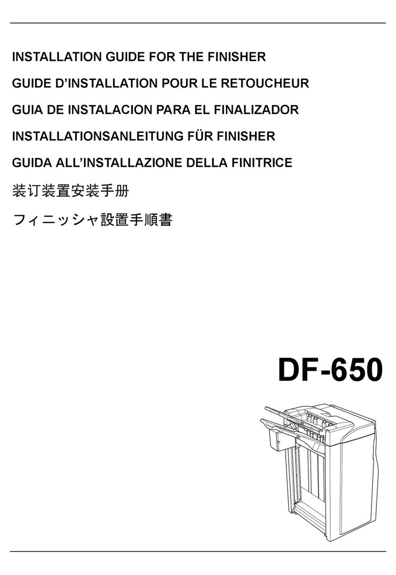
Konica Minolta FS-511 User manual

E-1
INSTALLATION MANUAL
4521-9550-00
FS-511 Finisher
Note:
Lifting the machine in an awkward position or
transporting it in a poorly balanced position could
result in personal injury. When transporting the
machine, assign an adequate number of persons
to the job and ensure that each person can take a
good position of not being excessively loaded.
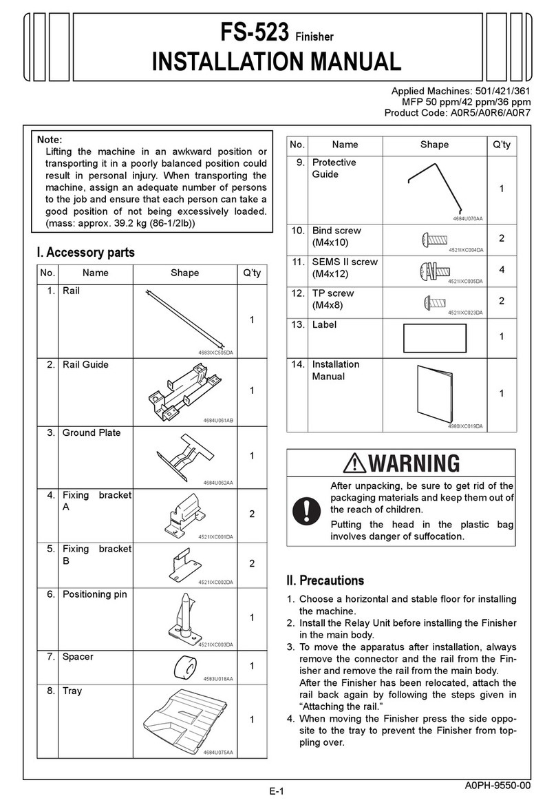
(mass: approx. 39.2 kg (86-1/2lb))
I. Accessory parts
II. Precautions
1. Choose a horizontal and stable floor for installing
the machine.
2. Install the Relay Unit before installing the Finisher
in the main body.
3. To move the apparatus after installation, always
remove the connector and the rail from the Fin-
isher and remove the rail from the main body.
After the Finisher has been relocated, attach the
rail back again by following the steps given in
“Attaching the rail.”
4. When moving the Finisher press the side oppo-
site to the tray to prevent the Finisher from top-
pling over.
No. Name Shape Q’ty
1. Rail
1
2. Rail Guide
1
3. Ground Plate
1
4. Fixing bracket
A2
5. Fixing bracket
B2
6. Positioning pin
1
7. Spacer 1
8. Tray
1
4683IXC505DA
4684U061AB
4684U062AA
4521IXC001DA
4521IXC002DA
4521IXC003DA
4583U018AA
4684U075AA
9. Protective
Guide
1
10. Bind screw
(M4x10) 2
11. SEMS II screw
(M4x12) 4
12. TP screw
(M4x8) 2
13. Label
1
14. Installation
Manual
1
set
After unpacking, be sure to get rid of the
packaging materials and keep them out of
the reach of children.
Putting the head in the plastic bag
involves danger of suffocation.
No. Name Shape Q’ty
4684U070AA
4521IXC004DA
4521IXC005DA
4521IXC023DA
4980IXC019DA
Applied Machines: 500/420
MFP 50 ppm/42 ppm

E-2
III. Installation procedures
1. Turn off the machine’s sub and main power
switches, and unplug the power cord from the
outlet.
2. Visually check the Finisher body, and remove the
lock tapes, lock materials and cushions from the
Finisher.
3. Use a nipper, etc. to cut the separation cover in
the two locations shown in the figure below.
4. Mount the ground plate and the rail guide to the
lower, left-hand side of the Paper Feed Cabinet or
the Desk.
(TP screw M4x8: 2pcs.)
Note:
Hook the Rail Guide to the claw on the Paper
Feed Cabinet or on the bottom face of the Desk to
secure it.
5. Insert the rail into the rail guide mounted in step
4.
Note:
Face the grooved end of the rail down and fit the
rail positively into position.
6. Pull out the right end of the rail from the right side
of the Paper Feed Cabinet or the Desk by approx.
60 mm, then insert a spacer into the tip of the rail.
Note:
Pull out the other end of the rail from the left side
of the Paper Feed Cabinet or the Desk to check
that the rail does not come out.
4521IXC014DA
Cushion
Be sure to remove here
Do not remove parts
Cushion
4521IXC015DA
4521IXC016DA
TP screw
M4x8
Rail Guide
Ground Plate
4521IXC006DA
Rail
4521IXC017DA
Spacer

E-3
7. Install the fixing brackets A and B in two loca-
tions. (SEMS ll screw M4x12: 2pcs each.)
Note:
Ensure that fixing brackets B face inward.
8. Install the positioning pin.
(Bind screw M4x10: 2pcs.)
Note:
Install the positioning pin so that its flat spring is on
the bottom side.
9. Connect the Finisher connector to the Relay Unit,
then fasten the connector cord using the nylon
clamp (Relay Unit accessory part) as shown
below to take up the slack in the cord. (TP screw
M3x6: 1 pc.)
10. Fit the rail into the mounting guide on the Fin-
isher tray side and insert the rail until a click is
heard.
Note:
At this time, do not press the Finisher up against
the main body, yet.
IV. Adjusting the position of the Finisher
1. Slowly move the Finisher toward the main body
and check the followings.
• Alignment between the positioning pin and the
hole in the Finisher. (height) (in the rear)
• Alignment between fixing bracket A and the fix-
ing bracket on the Finisher. (height) (at the front)
• Alignment between the surface A of the Relay
Unit and surface B of the Finisher. (height)
(Open the Finisher top cover to check it.)
• The gap between the Finisher and the main
body should be uniform. (See step 5 on page 4)
Note:
The following steps 2 to 7 should be performed
only if any part is found in inappropriate position.
2. Remove the Lower front cover of the Finisher. (2
screws)
4521IXC018DB
Positioning Pin
SEMS II screws
M4x12
Bind
screws
M4x10
Fixing brackets B
Fixing brackets A
4521IXC019DB
TP screw M3x6
(Relay Unit accessory parts)
Relay Unit
Nylon clamp
(Relay Unit accessory parts)
4521IXC020DA
4521IXC021DA
Surface B of the Finisher
Surface A of the Relay Unit
At the front In the rear
4521IXC007DA
Lower front cover

E-4
3. Pull up and remove the caster covers (2 loca-
tions).
4. Holding the lower adjusting bolt of the casters (4
places) in position, loosen the upper locking
bolts.
Then, turn the lower adjusting bolts to adjust the
height.
[Two in the rear]
If the positioning pin is higher
:Turn the bolt clockwise.
If the positioning pin is lower
:Turn the bolt counterclockwise.
[Two at the front]
If fixing bracket A is higher
:Turn the bolt clockwise.
If fixing bracket A is lower
:Turn the bolt counterclockwise.
• To adjust the height of the surface A of the Relay
Unit and surface B of the Finisher:
[Two each in front and rear]
If the surface A of the Relay Unit is higher
:Turn the bolt clockwise.
If the surface A of the Relay Unit is lower
:Turn the bolt counterclockwise.
5. Press the Finisher against the main body and
check that clearance between the two is equal at
points a and b.
Note:
If the clearance at a is not equal that at b, readjust
with the casters.
6. After the adjustment has been made, tighten the
upper locking bolts of the casters (4 places),
while holding the lower adjusting bolts in position.
7. Mount using the reverse of the procedures used
to remove this described in steps 2 and 3.
8. Install the tray and protective guide that come
with the Finisher at the locations shown.
4521IXC008DA
Caster covers
4521IXC009DA
Upper locking bolts
Lower adjusting
bolts
4521IXC022DA
a
b
4521IXC010DA
Upper locking bolt
Lower adjusting bolt
4521IXC011DA
➀
➁
➀
➁

E-5
V. Punch hole position adjustment
Make a sample copy in punch mode, then follow the
procedure below if the gap in hole positions is out of
the following specifications.
Standard value: 0 ± 2 mm
Fold the copy in half to check that holes are in cor-
rect alignment with each other.
1. Open the top cover of the Finisher and loosen the
screw that secures the hole punch guide plate.
Slide the green handle to the front or rear to
adjust the position of holes for hole punch.
2. Tighten the screw that secures the hole punch
guide plate.
Note:
Make a copy again and check for correct hole
positions.
If the specifications are not still met, readjust.
3. Close the top cover of the Finisher.
VI. Affixing the Label
Affix the labels to the position shown below.
VII. Registering the Serial Number
Register the serial number of the installed Finisher
to the machine.
The Serial Number is indicated on the back of the
Finisher.
4521IXC012DA
4521IXC013DA
Finisher top cover
Step
1. Plug the power cord of the machine to the
outlet, and turn on the machine’s sub and
main power switches.
2. Touch the “Utility/Counter” key.
3. On the [Utility/Counter] screen, touch
“Details” and press the keys in the following
order [Stop]+[0]+[0]+[Stop]+[0]+[1] to enter
[Service Mode].
4. Touch “System 1.”
5. Touch “Serial Number.”
6. Touch “Finisher.”
7. Enter the Serial Number of the Finisher, and
touch “OK.” (Touch “Shift” for switching
between upper case and lower case.)
8. Touch “END” on the screen for the Serial
Number list.
9. Touch “Exit” on the Service Mode to return to
the main screen.
4349IXC037DB4349U044AB
<ADF> <On Upper cover/Rr>
Table of contents
Other Konica Minolta Finisher manuals

Konica Minolta
Konica Minolta SD-511 User manual

Konica Minolta
Konica Minolta FS-534 User manual

Konica Minolta
Konica Minolta FS-528 User manual

Konica Minolta
Konica Minolta SD-505 User manual

Konica Minolta
Konica Minolta FS-533 User manual

Konica Minolta
Konica Minolta FS-518 User manual

Konica Minolta
Konica Minolta FS-501 User manual

Konica Minolta
Konica Minolta FS-523 User manual

Konica Minolta
Konica Minolta Magicolor 5550 User manual