Konica Minolta FS-528 User manual

E-1
INSTALLATION MANUAL
A10U955000
FS-528 Finisher
Applied Machine: 950
MFP: 95ppm
Product Code: A0Y5
I. Accessory parts II. Confirmation before installation
Note:
1. When transporting the Finisher, be sure to move
it in the direction illustrated below so as not to
deform the casters on the paper exit tray side.
2. Choose a horizontal and stable floor for installing
the machine.
3. When installing optional Post Inserter/Punch kit
to the Finisher, be sure to install it beforehand,
then install the finisher to the copier machine.
III. Installation procedure
1. Turn the Sub and Main power switches OFF, and
unplug the power cord from the outlet.
2. Remove the connector cover on the left side
cover of the machine. (1 screw)
No. Name Shape Q’ty
1. Machine
installation
plate/lower 15JMIXC001SA
1
2. Machine
installation
plate/upper 15JMIXC002SA
1
3. Paper exit
up-down tray
15JMIXC003SA
1
4. Paper exit
tray /1
15JMIXC004SA
1
5. Knob screw 2
6. TP screw
M4x6 2
7. TP screw
M4x14 2
8. Truss screw
M4x8 2
9. Fixing material
15JMIXC005SA
1
10. Installation
manual
1
Note:
Lifting the machine in an awkward position or
transporting it in a poorly balanced position could
result in personal injury. When transporting the
machine, assign an adequate number of persons
to the job and ensure that each person can take a
good position of not being excessively loaded.
(mass: approx. 65kg)
OK
NG
15JKIXC001SA
A10UIXC001CA
Connector cover

E-2
3. Install the machine installation plate (lower) on
the lower left side of machine. (TP screw M4x6: 2
pcs.)
4. Install the machine installation plate (upper) on
the upper left side of the machine. (TP screw
M4x14: 2 pcs.)
Note:
Use the screw holes engraved marking 920 to
install the screws and secure them tightly.
5. Visually inspect the Finisher.
6. Remove the locking tapes and the locking protec-
tion materials from the front door and the left side
of the Finisher.
7. Remove the locking tape from each guide plates.
8. Remove the stacker locking materials.
A10UIXC002CA
Main body installation plate (lower)
TP screws M4x6
A10UIXC003CA
TP screws M4x14
Main body installation plate (upper)
A10UIXC006CA
Locking tapes
Locking
protection
materials
Locking tapes
Locking tape
Three pieces
of locking
materials
Locking tapes
15VFIXE002SA

E-3
9. Remove the screw from the staple waste box.
10. Remove the screw from the locking material at
the back of the stacker, and pull out the stacker.
11. Remove the locking material at the back of the
stacker (1 screw).
12. Loosen the two rail-stopper fixing screws, and
pull out the stacker further.
13. Remove staple-locking material/1 (7 screws).
14. Remove staple-locking material/2 (2 screws).
15. Remove the two locking materials on the left side
of the stacker (2 screws each).
15VFIXE003SA
Locking
material
Staple waste
box screw
15VFIXE004SA
Locking material
A10UIXC007CA
Rail-stopper fixing screw
15VFIXE005SA
staple-locking material/1
15VFIXE006SA
staple-locking material/2
15VFIXE007SA
Locking materials

E-4
16. Remove the cushion materials and the locking
tape from inside the stacker.
(1) Remove the two cushion materials in the stapler.
(2) Pull out the two cushion materials from inside
the stacker in the direction shown by the arrows
in the illustration.
Note:
Be careful not to touch the cushion material on the
side stitch stopper.
(3) After the cushion materials are removed, remove
the locking tape from the rewind roller.
(4) Remove one locking tape from each of the two
staple cartridges.
17. Remove the two locking materials from inside
the stacker (3 screws each).
Remove the protection sheets (2 areas).
18. Open the staple unit horizontally, and remove
the cushion material in the center.
Note:
When opening the staple unit, be sure to press the
position shown in the picture.
15VFIXE011SA
Cushion materials
Locking tape
15VFIXE008SA
Cushion materials
Side stitch
stopper
Locking tape
15VFIXE012SA
Locking tapes
15VFIXE009SA
Protection sheet Protection sheet
Locking materials
Front Rear
15VFIXC010SA

E-5
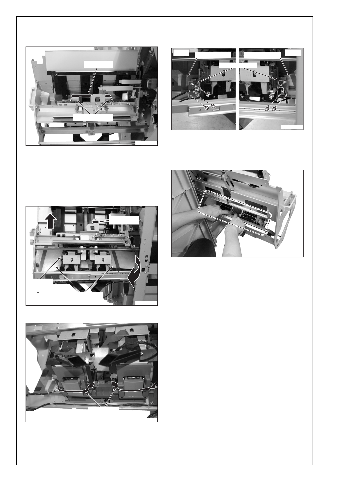
19. Install the staple-locking material/1 which is
removed in the step 13 with the removed
screws.
When installing, attach the fixing material included
in the package on the front side of staple-locking
material/1 as shown in the picture (to prevent los-
ing it).
Note:
• When moving the Finisher, be sure to install
staple-locking material/1 and all other fixing
materials. (Save all screws and locking materi-
als.)
• To prevent damage to the staple unit.
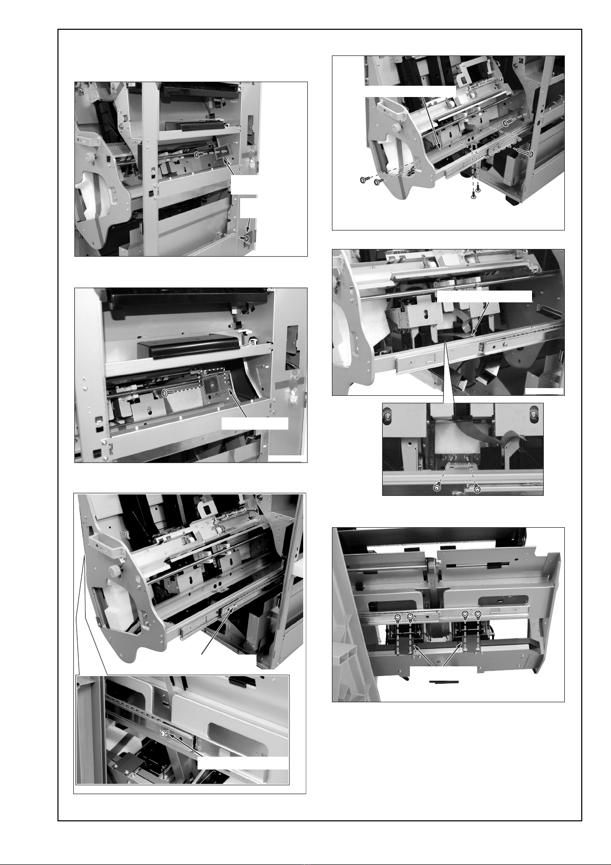
20. Tighten the two rail-stopper fixing screws, and
put the stacker back in position.
21. Connect the two connectors of the Finisher to
the connectors on the rear left side cover of the
machine.
22. Install the Finisher on the machine.
(1) Fit the hooks on the machine installation plates
(upper and lower) into the upper and lower
holes on the Finisher as illustrated below, then
lock them by pushing the Finisher to the back.
Note:
If the gap between Finisher and machine is not
equal from the top through the bottom, adjust it by
the height of the front and rear casters on the
paper exit side of the Finisher.
15VFIXE014SA
Staple locking material/1
fixing material
Machine connectors
Finisher connectors
15SJIXE010SB
A10UIXC004CA
Upper view
Lower view
Finisher
Finisher
Main body
Main body
Ԙ
ԙԙ
Ԛ
15JKIXE003SA
Skew
adjustment

E-6
(2) Fix the Finisher to the machine. (Knob screw: 2
pcs.)
23. Insert paper exit tray/1 into the sub tray paper
exit slot on the Finisher.
Note:
When installing paper exit tray/1, push the tray all
the way in until you hear a click.
24. Install the paper exit up-down tray on the up
down portion on the Finisher.
(Truss screw M4x8: 2 pcs.)
Note:
When installing the paper exit up-down tray, hook
the paper exit up-down tray to the four auxiliary
metal hooks and secure the tray.
IV. Confirmation of operation
1. Turn ON the Main and Sub power switches.
2. Execute the printing in the Sort mode to check if it
operated correctly.
3. Execute the printing in the Staple mode to check
if it stapled correctly.
A10UIXC008CA
Knob screws
15JMIXE015SA
Paper exit tray/1
15SJIXE013SA
Truss screws M4x8
Paper exit up-down tray
This manual suits for next models
1
Table of contents
Other Konica Minolta Finisher manuals

Konica Minolta
Konica Minolta FS-534 User manual

Konica Minolta
Konica Minolta FS-533 User manual

Konica Minolta
Konica Minolta SD-511 User manual

Konica Minolta
Konica Minolta FS-511 User manual

Konica Minolta
Konica Minolta Magicolor 5550 User manual

Konica Minolta
Konica Minolta SD-505 User manual

Konica Minolta
Konica Minolta FS-523 User manual

Konica Minolta
Konica Minolta FS-518 User manual

Konica Minolta
Konica Minolta FS-501 User manual