Konica Minolta FS-533 User manual

E-1
FS-533 Finisher
INSTALLATION MANUAL
A2YU-9553-02
Applied Machines: C558/C458/C368/C308/C258/C554e/C454e/C364e/C284e/C224e/C554/C454/C364/C284/
C224/554e/454e/364e/284e/224e
COLOR MFP: 55 ppm/45 ppm/36 ppm/30 ppm/28 ppm/25 ppm/22 ppm
MFP: 55 ppm/45 ppm/36 ppm/28 ppm/22 ppm
Product Code: A79K/A79M/A7PU/A7PY/A7R0/A5AY/A5C0/A5C1/A5C2/A5C4/A2XK/A4FJ/A161/A4FK/A4FM/
A61D/A61E/A61F/A61G/A61H
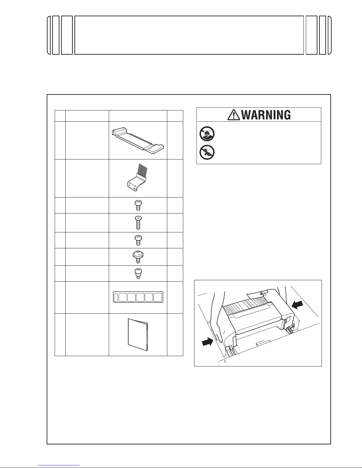
1. Accessory parts
* This part is used only when the Finisher is
installed to C554e/C454e/C364e/C284e/C224e/
C554/C454/C364/C284/C224/554e/454e/364e/
284e/224e.
Note:
• This manual provides the illustrations of the
accessory parts and machine that may be
slightly different in shape from yours. In that
case, instead of the illustrations, use the
appearance of your machine to follow the
installation procedure. This does not cause any
significant change or problem with the proce-
dure.
• If none of the later steps instruct you to use the
parts including screw and cover that you
removed following the instructions described in
this manual, discard them.
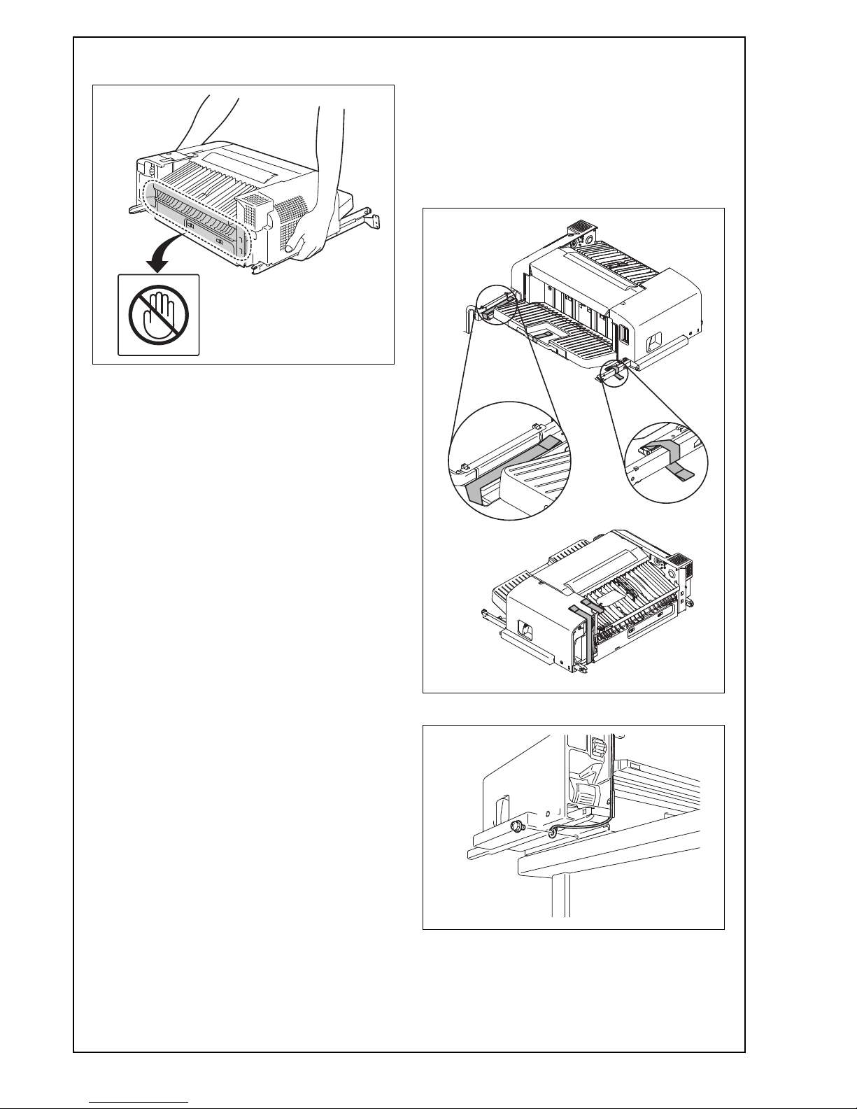
• When removing the finisher from the carton, be
sure to hold the finisher by the sides as shown
in the illustration.
No. Name Shape Q’ty
1. Rail cover
1
2. Mounting
bracket (anti-
static brush)*1
3. Screw A
(4 x 8 mm) 1
4. Screw B
(3 x 25 mm) 1
5. Screw C
(3 x 6 mm) 1
6. Screw D
(3 x 6 mm)*2
7. Shoulder screw 1
8. Label
1
9. Installation
manual
1
set
Keep this bag away from babies and
children. Do not use in cribs, beds,
carriages, or playpens.
The thin film may cling to nose and
mouth and prevent breathing. This bag is
not a toy.

E-2
• When carrying the finisher, be sure to hold the
finisher by the sides as shown in the illustration. 2. Installation procedures
(1) Turn OFF the power switch and unplug the
power cord from the power outlet.
(2) Remove protective tape and protective materials
and take out accessory parts.
Note:
Note that if you pull the lever after removing the
protective tape from the front rail, the front rail
pops out.
(3) Remove the screw and the washer.

E-3
Note:
When installing this option to C558/C458/C554e/
C454e/C554/C454/554e/454e, the following steps
steps (4) to (10) are performed only if the optional
output tray OT-506 is installed.
(4) Check whether the output tray has the snap-fit
hook illustrated below or not.
< When the machine has the snap-fit hook >
Go to step step (7).
< When the machine does not have the snap-fit
hook >
Go to step step (5).
(5) Open the front door of the main unit.
(6) Remove the upper left cover from the main unit.
(Three screws)
(7) Remove the output tray from the main unit.
(8) Reattach the upper left cover removed in step
step (6) to the main unit. (Three screws)
(9) Close the front door of the main unit.
(10) Remove the guide from the main unit.
< With the
snap-fit hook >
< Without the
snap-fit hook >
< With the snap-fit hook >
< Without the snap-fit hook >

E-4
(11) Remove the cover from the main unit as shown
in the illustration. (One screw)
(12) Remove the rear left cover from the main unit.
(Three screws)
(13) Remove the knockout from the cover removed
in step step (12) with nippers.
Note:
Remove the part shown in the illustration only.
(14) Peel the seal off the cover of the main unit as
shown in the illustration.
(15) Peel the seal off the main unit.
<C554e/C454e/C364e/C284e/C224e/C554/C454/
C364/C284/C224/554e/454e/364e/284e/224e>
(16) Attach the supplied mounting bracket (anti-
static brush) to the finisher. (Two supplied
screws D)
Note:
• Make sure not to deform the brush by touching
it.
• Make sure not to touch the upper surface of the
transport unit (A part) as it damages the guide
plates.
A

E-5
(17) To install the finisher, follow the steps below.
a) When inserting the finisher into the main unit,
be careful not to hit the exterior of the finisher
against the plate located at the rear left of the
main unit.
b) Adjust the finisher’s position to the right of the
plate and then move the finisher to the rear of
the main unit.
c) By fitting the ends of the finisher’s front and
back rails into the main unit’s rectangle holes,
join the finisher to the main unit.
Plate
Exterior
Plate

E-6
<C554e/C454e/C364e/C284e/C224e/C554/C454/
C364/C284/C224/554e/454e/364e/284e/224e>
(18) Use a rule or the like to fit the brush toward the
rear as shown in the illustration.
Note:
Make sure that brush touches the aluminum sheet
affixed to the bottom of the scanner unit.
(19) Secure the finisher with the supplied screw A
(rear side) and screw B (front side).
(20) Slide the finisher by pulling the lever.
(21) Place the supplied rail cover onto the rail of the
finisher.
Note:
Make the finisher’s harness come out from the rail
cover at the position shown in the illustration.
OK NG
Aluminum sheet

E-7
(22) Secure the rail cover with the supplied screw C
(front side) and the shoulder screw (rear side).
(23) Remove the cover shown in the illustration from
the rear of the main unit. (One screw)
(24) Plug in the two connectors of the finisher. Fit
the head of the cable tie into the mounting hole
on the main unit.
(25) Reinstall the cover that have been removed in
step (23). (One screw)
Note:
• Be careful not to pinch the harness.
• Insert two claws A into the holes on the main
unit cover first. Then fit two claws B into the
holes.
(26) Reattach the rear left cover removed in step
step (12) to the main unit. (Three screws)
(27) Slide the finisher and affix the label to the posi-
tion as shown in the illustration.
Connector
Cable tie
Claws B
Claws A
Table of contents
Other Konica Minolta Finisher manuals

Konica Minolta
Konica Minolta SD-505 User manual

Konica Minolta
Konica Minolta FS-501 User manual

Konica Minolta
Konica Minolta FS-528 User manual

Konica Minolta
Konica Minolta FS-523 User manual

Konica Minolta
Konica Minolta Magicolor 5550 User manual

Konica Minolta
Konica Minolta SD-511 User manual

Konica Minolta
Konica Minolta FS-518 User manual

Konica Minolta
Konica Minolta FS-534 User manual

Konica Minolta
Konica Minolta FS-511 User manual