Korg POLY-61 User manual

7
Model 8-435
ver. 1.0
INSTALLATION MANUAL
Rev. 2
© 2018 CHD Elektroserv is

P61-KBD
MIDI Interface for Korg Poly-61 Keyboard
Model 8-435 ver. 1.0
Copyright © 2018 CHD Elektroservis.
All rights reserved. No part of this publication may be reproduced in any form without the written permi ssion of CHD Elektroservis.
2
Contents page
1
11
1
INTRODUCTION
INTRODUCTIONINTRODUCTION
INTRODUCTION . . . . . . . . . . . . . . . . . . . . . . . . . . . . . . . . . . . . . . . . . . . . . . . . . . . . . . . . . . . . . . . . . .
. . . . . . . . . . . . . . . . . . . . . . . . . . . . . . . . . . . . . . . . . . . . . . . . . . . . . . . . . . . . . . . . . . . . . . . . . . . . . . . . . . . . . . . . . . . . . . . . . . . . . . . . . . . . . . . . . . . . . . . . . . . . . . . . . . . .
. . . . . . . . . . . . . . . . . . . . . . . . . . . . . . . . . . . . . . . . . . . . . . . . . . . . . . . . . . . . . . . . . .
3
33
3
1.1 MIDI INTERFACE KIT PARTS . . . . . . . . . . . . . . . . . . . . . . . . . . . . . . . . . . . . . . . . . . . . . . . . . . . . . . . 3
1.2 GENERAL INFORMATION . . . . . . . . . . . . . . . . . . . . . . . . . . . . . . . . . . . . . . . . . . . . . . . . . . . . . . . . . 3
2
22
2
MIDI INTERFACE INSTALLATION
MIDI INTERFACE INSTALLATIONMIDI INTERFACE INSTALLATION
MIDI INTERFACE INSTALLATION . . . . . . . . . . . . . . . . . . . . . . . . . . . . . . . . . . . . . . . . . . . . . . . . . . . . .
. . . . . . . . . . . . . . . . . . . . . . . . . . . . . . . . . . . . . . . . . . . . . . . . . . . . . . . . . . . . . . . . . . . . . . . . . . . . . . . . . . . . . . . . . . . . . . . . . . . . . . . . . .
. . . . . . . . . . . . . . . . . . . . . . . . . . . . . . . . . . . . . . . . . . . . . . . . . . . . .
3
33
3
2.1 RELEASING OF THE INSTRUMENT COVER . . . . . . . . . . . . . . . . . . . . . . . . . . . . . . . . . . . . . . . . . . . . 4
2.2 MIDI-IN SOCKET MONTAGE . . . . . . . . . . . . . . . . . . . . . . . . . . . . . . . . . . . . . . . . . . . . . . . . . . . . . . . 4
2.3 BUNCHED CABLES MONTAGE . . . . . . . . . . . . . . . . . . . . . . . . . . . . . . . . . . . . . . . . . . . . . . . . . . . . . . 6
2.4 INTERFACE BOARD PLACEMENT . . . . . . . . . . . . . . . . . . . . . . . . . . . . . . . . . . . . . . . . . . . . . . . . . . . . 7
2.5 INSTRUMENT RE-ASSEMBLY . . . . . . . . . . . . . . . . . . . . . . . . . . . . . . . . . . . . . . . . . . . . . . . . . . . . . . . 8
Document :
8435_install_rev2
Manufacturer :
CHD Elektroservis
CHD ElektroservisCHD Elektroservis
CHD Elektroservis
Nad kundratkou 27, 19000 Praha 9, Czech Republic
info@chd-el.cz www.chd-el.cz

P61-KBD
MIDI Interface for Korg Poly-61 Keyboard
Model 8-435 ver. 1.0
Copyright © 2018 CHD Elektroservis.
All rights reserved. No part of this publication may be reproduced in any form without the written permi ssion of CHD Elektroservis.
3
1
11
1
INTRODUCTION
INTRODUCTIONINTRODUCTION
INTRODUCTION
The Korg P61 Keyboard MIDI Interface enables the integration of MIDI in your P61. The instrument's keyboard
can be controlled with this MIDI interface in parallel manner. The interface only receives MIDI data so it has
MIDI input only.
1.1
1.11.1
1.1
MIDI INTERFACE KIT PARTS
MIDI INTERFACE KIT PARTSMIDI INTERFACE KIT PARTS
MIDI INTERFACE KIT PARTS
Parts of the MIDI interface kit
Parts of the MIDI interface kitParts of the MIDI interface kit
Parts of the MIDI interface kit
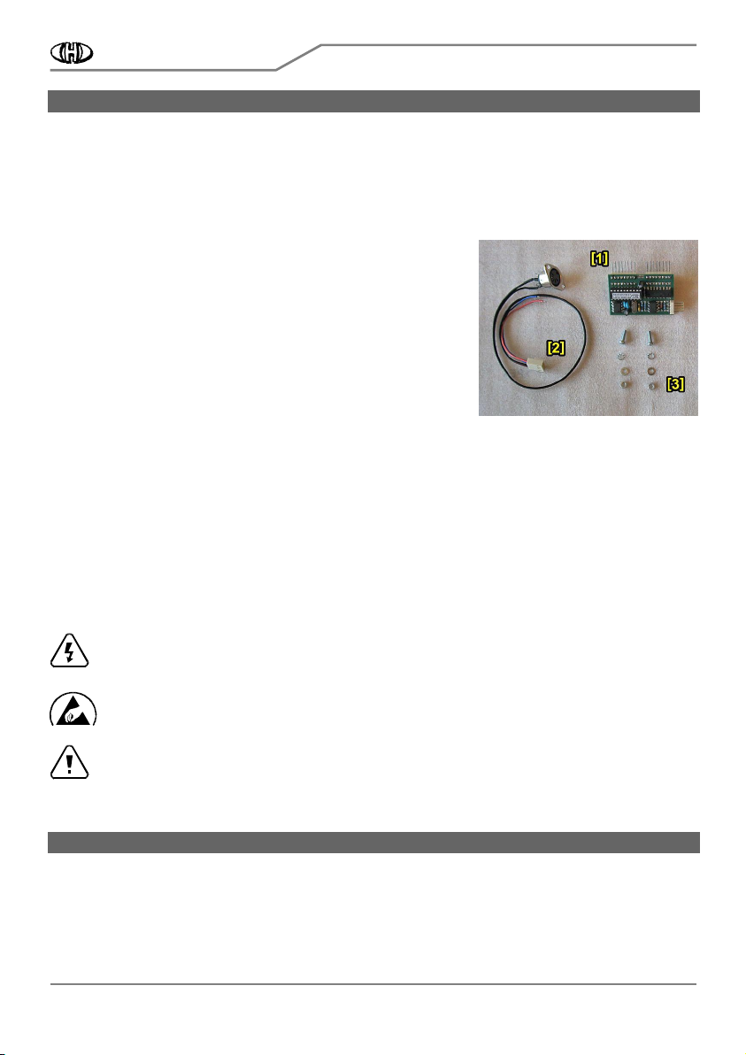
The supplied MIDI interface kit contains all necessary parts, materials,
and detailed installation instructions. The kit contains:
1. MIDI interface board
2. Bunched cables with MIDI socket
3. All necessary coupling elements (screws, nuts, washers)
4. Owner’s and Installation manuals in printed form
1.2
1.21.2
1.2
GENERAL INFORMATION
GENERAL INFORMATIONGENERAL INFORMATION
GENERAL INFORMATION
The installation of all interface components is very easy. If you follow the instruction from this manual there will
be no major problems during the installation procedure. The cover of the instrument will not be markedly
damaged during the installation. The physical appearance of the vintage instrument remains nearly the same as
before the installation. If necessary, the interface can be removed and the instrument restored back to original
appearance. All original features of the Korg Poly-61 are kept. The instrument can be used the same way as
before the retrofitting.
The following tools are necessary for the installation: Phillips screwdriver, driller, drills 3,2 and 16 mm, smaller
rasp, pliers, soldering iron (a low heat iron and soldering paste).
Attention !
Attention !Attention !
Attention ! Disconnect the instrument form the mains prior to the installation. Otherwise, there is a
risk of the electric shock!
Attention!
Attention!Attention!
Attention! Observe precautions for handling electrostatic discharge sensitive devices!
Attention!
Attention!Attention!
Attention! The producer is not responsible for any eventual mechanical or electrical damage of the
instrument caused by the infringement of the described installation procedure or by careless
manipulation during the installation of the MIDI interface!
2
22
2
MIDI INTERFACE INSTALLATION
MIDI INTERFACE INSTALLATIONMIDI INTERFACE INSTALLATION
MIDI INTERFACE INSTALLATION
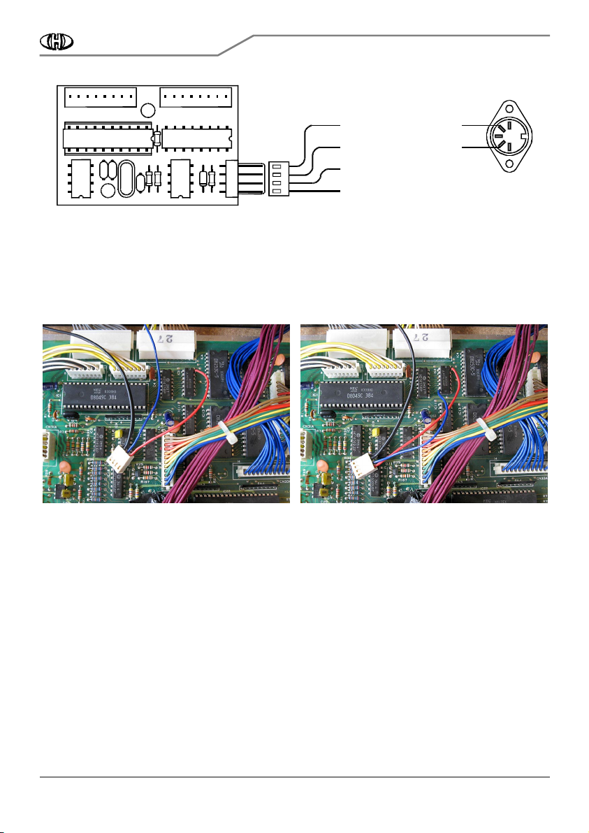
The interface is connected to the keyboard switch matrix of the instrument in a parallel fashion (pic. 1). There
are two versions of instrument’s main PCB board. Older is named KLM475, newer is named KLM-509. Although
some little difference is between these boards, the interface is applicable to both versions of instrument’s main
board.

P61-KBD
MIDI Interface for Korg Poly-61 Keyboard
Model 8-435 ver. 1.0
Copyright © 2018 CHD Elektroservis.
All rights reserved. No part of this publication may be reproduced in any form without the written permi ssion of CHD Elektroservis.
4
Pic. 1
Pic. 1 Pic. 1
Pic. 1 -
--
- Electrical connection in the instrument
Electrical connection in the instrument Electrical connection in the instrument
Electrical connection in the instrument
2.1
2.12.1
2.1
RELEASING OF T
RELEASING OF TRELEASING OF T
RELEASING OF THE INSTRUMENT COVER
HE INSTRUMENT COVERHE INSTRUMENT COVER
HE INSTRUMENT COVER
a) Unscrew the four screws from the bottom of the instrument (pic. 2.1-1) and the four screws on the front
panel (pic. 2.1-2).
b) Carefully open the instrument - lift off the instrument’s front panel (pic. 2.1-3). Instrument’s main board
(KLM475 / KLM-509) is located at left side inside the instrument.
Pic. 2.1
Pic. 2.1Pic. 2.1
Pic. 2.1-
--
-1
11
1
Pic. 2.1
Pic. 2.1 Pic. 2.1
Pic. 2.1-
--
-2
22
2
Pic. 2.1
Pic. 2.1Pic. 2.1
Pic. 2.1-
--
-3
33
3
2.2
2.22.2
2.2
MIDI
MIDIMIDI
MIDI-
--
-IN SOCKET MONTAGE
IN SOCKET MONTAGEIN SOCKET MONTAGE
IN SOCKET MONTAGE
There are two possible ways to install the MIDI-IN DIN socket:
If you do not want to mechanically damage the rear panel of the instrument, take out the MIDI cable through
the slot on the left side of the keyboard for example (see pic. 2.2-1).

P61-KBD
MIDI Interface for Korg Poly-61 Keyboard
Model 8-435 ver. 1.0
Copyright © 2018 CHD Elektroservis.
All rights reserved. No part of this publication may be reproduced in any form without the written permi ssion of CHD Elektroservis.
5
It is better to place the MIDI-IN connector on the rear panel of the instrument for easier operation. It is
necessary to drill three holes in the instrument panel however. The MIDI-IN connector can be installed near
the jack connectors (see pic. 2.2-2). In that case, MIDI-IN connector installation procedure is as follows:
Pic. 2.2
Pic. 2.2Pic. 2.2
Pic. 2.2-
--
-1
11
1
Pic. 2.2
Pic. 2.2 Pic. 2.2
Pic. 2.2-
--
-2
22
2
a) Flip the front cover over and return it to its original closed position on top of the synth.
b) Drill three holes (one with 16 mm diameter and two with 3,5 mm diameter) in the rear panel (see pic. 2.2-3).
Work carefully so as to not drill the parts inside the instrument (pic. 2.2-4).
Pic. 2.2
Pic. 2.2Pic. 2.2
Pic. 2.2-
--
-3
33
3
Pic. 2.2
Pic. 2.2 Pic. 2.2
Pic. 2.2-
--
-4
44
4
c) Clean the edge of the holes with small rasp (pic. 2.2-5). Also clean the holes from the inside after the
instrument opening..
d) Clean all iron sawdust and raspings from the inside of the instruments
Clean all iron sawdust and raspings from the inside of the instrumentsClean all iron sawdust and raspings from the inside of the instruments
Clean all iron sawdust and raspings from the inside of the instruments, they can cause short circuits or serious
electrical damage if left in the instrument. Please clean the instrument carefully!
e) Get flat connector of bunched cables (part of the kit) through the hole in rear panel into the instrument (pic.
2.2-6).
f) Insert the DIN socket into hole in rear panel (pic. 2.2-7) and fix it to the panel using screws, washers and nuts
(pic. 2.2-8). All material is a part of the kit.

P61-KBD
MIDI Interface for Korg Poly-61 Keyboard
Model 8-435 ver. 1.0
Copyright © 2018 CHD Elektroservis.
All rights reserved. No part of this publication may be reproduced in any form without the written permi ssion of CHD Elektroservis.
6
Pic. 2.2
Pic. 2.2Pic. 2.2
Pic. 2.2-
--
-5
55
5
Pic. 2.2
Pic. 2.2 Pic. 2.2
Pic. 2.2-
--
-6
66
6
Pic. 2.2
Pic. 2.2Pic. 2.2
Pic. 2.2-
--
-7
77
7
Pic. 2.2
Pic. 2.2 Pic. 2.2
Pic. 2.2-
--
-8
88
8
f) You may also want to label the MIDI socket ("MIDI - INPUT") using self-adhesive foil, for example (pic. 2.2-2).
2.3
2.32.3
2.3
BUNCHED CABLES MONTAGE
BUNCHED CABLES MONTAGEBUNCHED CABLES MONTAGE
BUNCHED CABLES MONTAGE
Pic. 2.3
Pic. 2.3 Pic. 2.3
Pic. 2.3-
--
-1
11
1
The bunched cables (part of
the kit) has a four-pin
connector on one end (pic.
2.3-1). There are four
terminals. Two of them (Nr.
3, Nr. 4) are already fixed
to newly installed DIN -
MIDI-IN connector. Next
two (Nr. 1, Nr. 2) must be
soldered to the
instrument's KLM-475 /
KLM-509 board (pic. 2.3-2).

P61-KBD
MIDI Interface for Korg Poly-61 Keyboard
Model 8-435 ver. 1.0
Copyright © 2018 CHD Elektroservis.
All rights reserved. No part of this publication may be reproduced in any form without the written permi ssion of CHD Elektroservis.
7
Pic. 2.3
Pic. 2.3Pic. 2.3
Pic. 2.3-
--
-2
22
2
CN30DCN29P 4
3
2
1
Bunched
cables
Inte
r
f
ace boa
r
d
MIDI - IN- (DIN pin Nr. 5)
MIDI - IN+ (DIN pin Nr. 4)
+5V (KLM-475 / KLM-509 board)
GND (KLM-475 / KLM-509 board)
MIDI - Input
a) Solder the red cable (Vcc +5V - pin Nr. 1 of interface’s connector) to the power distribution +5V on the KLM-
475 / KLM-509 board. The most suitable place is lead (pin) Nr. 14 of the IC3 (pic. 2.3-3).
b) Solder the blue cable (GROUND - pin Nr. 2 of interface’s connector) to the ground potential on the KLM-475 /
KLM-509 board. The most suitable place is is lead (pin) Nr. 7 of the IC3 (pic. 2.3-4).
Pic. 2.3
Pic. 2.3Pic. 2.3
Pic. 2.3-
--
-3
33
3
Pic. 2.3
Pic. 2.3 Pic. 2.3
Pic. 2.3-
--
-4
44
4
2.4
2.42.4
2.4
INTERFACE BOARD
INTERFACE BOARD INTERFACE BOARD
INTERFACE BOARD PLACEMENT
PLACEMENTPLACEMENT
PLACEMENT
a) Detach bunched cables from CN29P and CN30D connectors on KLM-475 / KLM-509 board These cables lead
from instrument’s keyboard (pic. 2.4-1).
b) Plug interface board onto CN29P and CN30D connectors on KLM-475 / KLM-509 board so that flat four-pin
plug on interface’s board is to right (pic. 2.4-2).
c) Plug the connectors of the bunched cables from the keyboard onto the plugs on the interface’s board (pic.
2.4-3). Be careful, the connectors must not be rotated or exchanged. Locks of the connectors must be down.
Bunched cables with black and white colored wires are left (CN29P connector) and bunched cables with yellow
and white colored wires are right (CN30D connector).
d) Plug the flat 4-pin connector of newly installed bunched cables (from +5V, GND and MIDI-IN socket) to the
flat connector on the MIDI-In interface board (pic. 2.4-4). The connector is shaped such that it cannot be
connected the wrong way - there are locks on it.

P61-KBD
MIDI Interface for Korg Poly-61 Keyboard
Model 8-435 ver. 1.0
Copyright © 2018 CHD Elektroservis.
All rights reserved. No part of this publication may be reproduced in any form without the written permi ssion of CHD Elektroservis.
8
Pic. 2.4
Pic. 2.4Pic. 2.4
Pic. 2.4-
--
-1
11
1
Pic. 2.4
Pic. 2.4 Pic. 2.4
Pic. 2.4-
--
-2
22
2
Pic. 2.4
Pic. 2.4Pic. 2.4
Pic. 2.4-
--
-3
33
3
Pic. 2.4
Pic. 2.4 Pic. 2.4
Pic. 2.4-
--
-4
44
4
2.5
2.52.5
2.5
INSTRUMENT RE
INSTRUMENT REINSTRUMENT RE
INSTRUMENT RE-
--
-ASSEMBLY
ASSEMBLYASSEMBLY
ASSEMBLY
a) Turn over the front panel of the instrument.
b) Reattach the front panel to the sides of the instrument with four screws (pic. 2.5-1) and reattach four screws
to the bottom of the cover (pic. 2.5-2). This is the reverse procedure of that described in the chapter 2.1.
Pic. 2.5
Pic. 2.5Pic. 2.5
Pic. 2.5-
--
-1
11
1
Pic. 2.5
Pic. 2.5Pic. 2.5
Pic. 2.5-
--
-2
22
2
The installation of the MIDI kit is now finished, the instrument is ready for use with MIDI. Please read the user’s
manual carefully before the MIDI interface usage.
Other manuals for POLY-61
3
This manual suits for next models
2
Table of contents
Other Korg Media Converter manuals